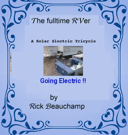
Solar Electric Tricycle
Dedication


I Dedicate this book to my parents whom enjoyed the RV
Lifestyle
We would also like to dedicate this book to all
those who dream of going the RV lifestyle and maybe just need a little help along the way.
Preface
With the ever looming climate change due to use of carbon producing processes, we all need to consider alternatives that help the planet instead of hurting it. Insects and Animals and even Marine species adapt to their surroundings as much as possible, but man kind is like a parasite, it consumes and changes the environment to meet it's needs. Because of these alterations it affects the natural state of the planet and the planet is fighting back. If it doesn't fight back, Earth will become a barren chuck of rock devoid of all life.
We have the knowledge and ability to make the necessary changes now. In this book I will focus on the Tricycles as an option for low cost travel in certain circumstances. The premise is to stop being a throw away society and become a re-purpose and restore one instead.
 |
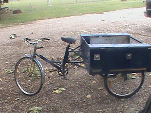
Depicted here is a full feature solar electric tricycle capable of travel at up to 30mph (50kph) which doesn't have insurance costs, fuel costs, high maintenance costs. It has a range from 33 miles to 100 miles per charge. For those in the market for a car which new must be electric by 2030 this can be an option to save for one. If your use is to get groceries, commute to/from work or school and you regularely travel alone this can be a sweet option. No $1000 a year insurance, $2500 a year fuel, $3400 a year maintenance, and no $300 to $900 a month in payments so you can potentially save $8000 a year or more towards a car without limiting you. Maybe your a senior without a license anymore you can get out and about with one of these. |
Under the governments plan, New vehicles must be EV only by 2030, Used vehicles sold must be EV only by 2035, and all ICE vehicles must be off the road by 2040. We are talking of replacing 24 million current vehicles with electric by 2040. That is 16 short years. The auto makers know the writing is on the wall and are stepping up with new EV offerings. The ICE (internal combustion engine) reign is over.
The move to Green technology by 2040 is a good thing and will see the following changes:
- 24 million cars, trucks, Vans, suv's will become obsolete and replaced by 2040
- ICE Trade-in values drop 50% by 2030
- ICE Trade-in values drop 75% by 2035
- ICE Trade-in values drop to 0 by 2040.
- Quads, snow mobiles, motorbikes, atv's, collector cars will become unuseable
- Class A, B, C motor coaches will be affected as well
- RV travel trailers, 5th wheels, pop-up trailers will need stronger EV vehicles to pull them
- Not everyone can afford to replace their automobile
- Demand for motors, Inverters, Battery packs will increase
- Charging stations will be needed
- 500,000 tonnes of engines, 250,000 tonnes of transmissions will have to be dismantled and melted down
- Job losses in petrochemical, gas stations, Engine Mechanics, and others.
- Gas stations will be gone
- Petrochemical industry will be trimmed back to natural gas, propane, oils for lubricants
- Roadside service will need portable propane generators to help travelers reach a charge point.
- Wreckers and auto-re-cycler businesses will be overwhelmed with cars with no market for the parts
- Lead acid battery makers and re-builders will have loss of market
- Electric grid demand goes up by 200 Million KW per week for Canada.
Some may think it won’t happen hedging on hopes the government will change. Some will refuse to go EV due to reports of poor EV performance until it is too late, and some will protest the changes and the poor trade-in values on their vehicles.
 Some local governments have been trying to scare people into petitioning for the change not to happen siting that we can’t support the demand on the power grid, loss of petroleum revenue and petroleum jobs. But they are just human form of an ostrich that figures if they can’t see the preditor the preditor (Earth fighting back) can’t see them.
Going with a Tricycle may not seem like much but every bit can help
I will be touching on how we might deal with the above list of problems as we go green. My focus will be on the Solar-Electric-Tricycle in this issue and even more-so in my issues on vehicle conversion to Solar-Electric.
Chapter 1 Choices
In this issue, I focus on Simple Transportation for one person to travel for free to work, school, shopping or visiting friends and loved ones.
Not everyone is the same:
Businesses need vehicles with capacity and range to fit their needs. Some place the owness on owner / operators like couriers, taxi drivers, food and prescription delivery, and transports. Others shoulder the burden with vehicles of their own. The solar electric Tricycle is a cost effective option for home food deliver, liquer delivery, prescription delivery and even couriers of small packages.
Many people are in hard times and saddled with loans on their current ride. A ride that in 6 years will be worth 50% or less of what they paid for it. In 11 years won't be worth anything. If you commute to work or school, This option can save you thousands of dollars in cost of fuel and maintenance so you can pay down your loans and save for an EV.
Others also in hard times are fighting to make ends meet while nursing their fully paid for ride. A ride that eventually must be replaced and when that time comes may be worth nothing. If you commute to work or school, or even grocery shop, This option can save you thousands of dollars in cost of fuel and maintenance so you can save for an EV.
New entrants to the market are at the mercy of credit bureaus and lending institutions. In many cases the option is to buy an old junker for cash or go through a loan shark paying outrageous interest. If you commute to work or school, or even grocery shop, This option can save you thousands of dollars in cost of Insurance, Loans, fuel and maintenance so you can save for an EV without the hasle.
Going electric
Has become just as mind boggling as keeping a roof over your head. I hope to shed light on the topic to help.
The pages that follow address these choices.
Chapter 2 The Grand Plan
My grand plan began as a plan to convert my motorhome to an EV-Motorhome, augment this with a Solar-Electric tricycle for short commutes, and obtain a vehicle to convert into a Solar-electric vehicle. The intent was to fully document these ventures for others who may wish the same course of action.
Then suddenly came NEWS of the Canadian Government's climate actions plans. I was doing my part to honor my mother's wish that I make my Motorhome into an EV and pass on my knowledge. It's no longer about me, I am part of a bigger picture. A picture that will see all of North America being net zero by 2050.
Net zero by 2050 means all forms of power, heating, transportation will be from renewable resources and devoid of carbon production. Canada was one member of 150 countries back 1958 that promised to end coal production and use by 2000, end use of climate damaging carbon emissions by factories, transportation sector, homes by 2030 and in so doing save our planet.
On a federal level, the government is offering people whom wish to save money on their home operations incentives such as rebates on :
- Change out hot water tanks (on gas) to electric instant hot water
- Cover the cost of Solar panels for their homes in 10 select regeons if they cover the installation costs
- Carbon levy rebates to low income households
- Installation of heat pumps
Locally we had a local government that wanted to honor Canada's agreement to the world and end coal by 2030, put more resources into green energy and stop subsidizing petrochemical but the people voted them out in favor of a government that promised to increase coal production and use, give more money to rich oil barons, and ask the people to petition for an end to go green to save the planet.
The auto-makers know that EV vehicles will replace the ICE by 2040. Both USA and Canadian governments have made this clear. Even the EU & China have moved this way already. Political opposition parties have always been a thorn to progress that is why virtually nothing has been done for 66 years. Heck it only took 69 years from the first airplane to putting a man on the moon. I am a problem solver at heart, instead of saying it can't be done, let's say let's find the way to get it done.
We have 16 years and the clock is ticking, 24 million vehicles need to be converted in Canada and 440 Million in the USA. The alternative is that 464 million vehicles become junkyard trash with no market for them. The count goes up on average by 3% per year! The auto-makers are in their glory right now, they see that they have 500,000,000 potential sales in the next 16 years with no regard to the same number of trashed vehicles worth nothing.
To address these concerns: (red=bad green = hoped)
- Federal Government:
- 24 million owners must replace their vehicles
- 24 Million vehicles become scrap which is environmentally disastrous
- National power grid demand up by 200 million KW per week
- Tax free savings plan for EV conversion or purchase
- Grants or low interest loans for low income people to convert their ride, exchange their ride, or purchase EV
- Vehicle Conversion Regulations (inspection, modification, etc.)
- New vehicle Battery standards
- Provincial Government:
- Stop subsidizing petrochemical
- Stop fighting against the federal government
- Stop coal production and use
- Put more effert into green technology
- Offer incentives to atract new EV busineses to locate locally
- Municipal Government:
- find a way to get involved
- Lending Institutions and banks:
- Tax free savings plan for EV conversion or purchase
- Be more supportive of green technology
- Businesses:
- Gas stations will have deminishing sales and must become charge stations.
- Lead acid battery makers and re-builders will have new market by making Gcells for EV. Owners can replace worn Gcells just like they do lead acid batteries.
- Auto sales lots will have to change
Currently they give higher trade in value to ICE vehicles and not much for EV because they don't understand a simple motor that makes no noise and a engine that is noisy, polluting, with 1000's of parts. As ICE is phased out vehicle value on ICE will drop to 0 trade-in with-in 11 years.
- Insurance providers have to change
This business of righting off EV vehicles just because they use battery instead of gas or diesel has to change. They right off 30,000 to 80,000 dolars of battery because no industry is established to check or repair them.
- New Battery Builders / rebuilders business
will need staff to make Gcells
- New Solar panel Businesses focused on Vehicles
will need staff to make custom panels
- Auto makers will need to change from 1 giant pack to 2 smaller packs called banks with each bank being made from user replaceable Gcells.
- Auto Recycle and wrecking yards
You current have the remnants of 60 or more years of wrecked automobiles which you break down into parts for resale and scrap the rest as metal and plastic waste. Over the next 16 years the market for your parts will become zero and all those wrecked and stacked EV's will just keep increasing.
You need to partner with battery rebuilders,
You need to partner with Conversion shops that need you motors inverters and charge ports.
Businesses will be less overwhelmed if vehicles are converted instead of scrapped. Converted vehicles will still need parts so market for the parts remain.
- New conversion shops will be needed
24 Million vehicles to be inspected (inspectors needed)
Auto mechanics will be needed to remove ICE parts for recycle
Wrecked EV can source motors, inverters, battery packs, etc for conversion.
- Some one needs to take my crude designs of Universal dash controler, Battery technology, and solar plans and build our better future.
- General Public:
- Low income owners need way to save for EV
- Quads, snow mobiles, motorbikes, atv's that you wish keep will need conversion too
- Class A, B, C motor coaches will need to be converted to EV
Now in this documentation I will outline how a Solar electric Tricycle can be your best friend.
Armed with these plans people will benefit from choices to meet their needs when we go green by 2040.
Chapter 03 Travel for free with an EV Tricycle
Making a Solar-Electric Tricycle
This project began as a means to supply transportation while also proving out concepts for EV construction. I live as a full time RV -er. Due to injuries I find it hard to walk 3 city blocks to get groceries or 4 city blocks
to refill my propane. After my mom passed I had to give up my car to cover expenses since I no longer had her share. Her final requests were that I covert my Motor home into a full EV and pass on my knowledge to new generations.
While she was alive I did start plans to make an EV-MotorCoach and wrote books on numerous topics to pass on what I know. This is my 10th book begun about 2 months after her passing.

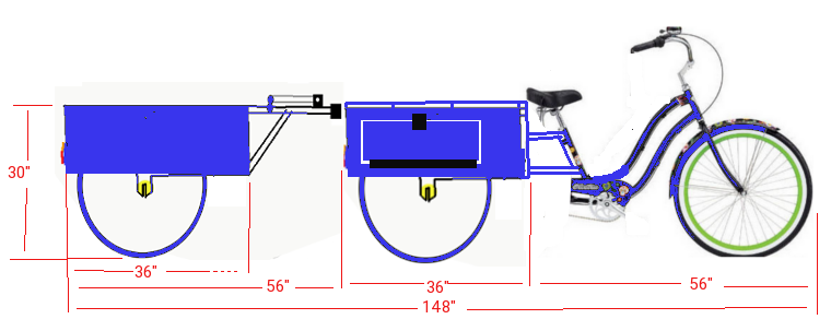
This was my original concept. A tricycle run from battery charged by either solar or 120v and with a range of 50 miles (83.33km). It should be 4ft wide and have a basket 30” x 36” and have a trailer with a similar basket and fold away solar panels. I was hoping for maximum speed of 50mph or possibly 60mph.
As I got into planning I soon learned that an Electric Tricycle can not be above 4ft wide, can not travel faster than 30mph or it must be registered, licensed, and insured as a motor vehicle.
** I revised the
plan **
The take away on this project is that it was originally designed as a 1440watt 48v with 2A to 4A solar built-in recharge and 120v AC built-in 10A charger can deliver fuel free transportation at 50kph with a range of 144kms. It's battery capacity can extend to 96 Ah up from 30 Ah which can provide for up to 580kms. As
I progressed, my plans and targets needed to be revised.
As it stands now, my build of the basic frame is:
- Fame 90 lbs 1400 lbs capable GVWR
- 2 x 24v @ 36A battery banks, Pack weight 30 lbs
- Electronics and wheelchair motor 40 lbs
- Solar panels 2A to 4A 52 lbs
- Curb weight 212 lbs
- Payload 420 lbs
- GVWR 632 lbs
- Maximum speed 30mph (50kph)
- Kw = 24v x 72A = 1.728Kw
- Range empty/full 432 lbs / 632 lbs
1.728/0.0432 = 40miles (66kms)
1.728/0.0632 = 27miles (45.5kms)
- Upgrade batteries to 2 x 96A = 4.608Kw
4.608/0.0522 = 88miles (147kms)
4.608/0.0722 = 63.82miles (106.3kms)
- While my build is using a wheelchair motor in a rear wheel drive configuration on 24v,
options for 48v front hub drive, 24v front wheel drive, and 48v rear wheel drive can be done
48v @ 36A = 1.728Kw , 48v @ 60A = 2.88Kw
28 to 40 miles \\ 45.5 to 66miles
Incorrect data on range calculations had resulted in my earlier exagerated figures. I have provided plans for 4 EV-Trike versions. They all use the same Tricycle framework but now you have the option to do 48v FWD, 24v FWD, 24v Mid-Drive, or even use converted 24v wheelchair drive. Hope you find my offering of use.
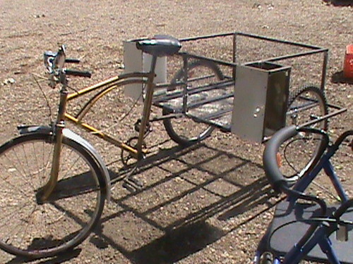
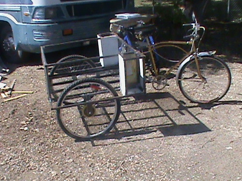
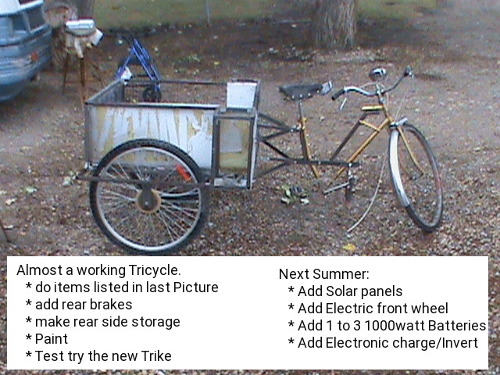
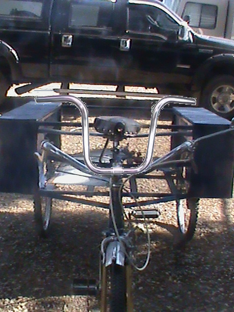
**Please be advised that I am still constructing my E-Tricycle so the Tricycle goes from actual photo's to artistic renditions.**
The intention was to make a solid frame with a custom basket for the back. To mount the two rear triangles to the solid basket frame and secure it to the down pipes of the two outer down seat pipes and the
inner Seat pipe such that the pedals could line up to make
interconnection of the pedals. But, and there is always a but, to make it work, I found out that a tig welder would be needed (which is not locally available). Also, joining weldable steel to the carbon fiber or aluminum frame components would not be possible except by using bolts.
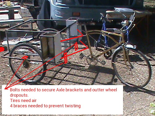
The bolt method would take a minimum of two bolts at each Down pipe and two bolts at each of the rear triangles. Then the cross brace at the back of the inner triangles would also need a bolted method to secure it There is not much clearance for this brace to be fastened to a regular bike triangle at the back. The rear wheels also might be obstructed by the bolts. Looking into the topic a bit, I investigated what is available in carbon fiber or aluminum stock to make the frame if I invested in a tig welder and found the only way to get enough stock might be to obtain more bicycles to cut up.
I turned my attention to the wealth of left over pieces that would result from making this Trike. 3 bicycles have 3 front tires, 3 rear tires, 3 full frames, 3 pedal sets with sprockets. So it occurred to
me that if I make the trailer instead of buying the small available one, I could possibly use up the excess materials. In a later chapter I detail the making of the trailer. And it was that trailer planning that came to solve my problem here. The trailer will use two
discarded front tires with steel frame and basket with wheel dropouts designed to accommodate the front tires. A similar frame will make the back of the Trike. The difference being that the trike frame will have dropouts designed for the rear driveline wheels, and instead of
the tow bar it will have the mounting for the three seat down pipes. Yes there will be 6 bolts needed (2 per down pipe) but the entire back can be welded as can the bolt nuts to make a very strong structure.
E-Tricycle Construction
Rear assembly concept:
A new square tube steel framework will serve as our rear frame. We make a square lower frame 46" by 36". The wheel wells are now known at 4.5" width and we know the basket will be 30" x 36" so this leaves us 3.5" for side pockets. All framing is done with 0.5" square steel tubing.
With the Framing planned, it's time to visit the local welding shop and get the estimate for frame construction. Besides the metal square tubing, there will be 20 welds for the framing plus another 24 welds to join the top and bottom frames. If I include the optional 4 uprights between the Electrical and back storage another 8 welds will
be needed. The estimate came in higher than expected at $500 for the trike and trailer.
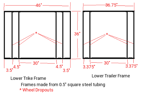
 Lower steel rear frame: Upper steel Rear frame:
Framing:
- 0.5"x 46" 4pcs
- 0.5"x 35" 10pcs>
- 0.5"x 15" 8pcs
- 0.5"x 15" 4pcs (optional)
- 0.25" x 2.5" x 2.5" Flat Steel dropouts
Dropouts are centered at 15" from the Back
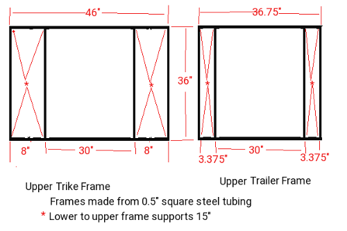
For the upper frame we almost duplicate the lower frame only we don't need the inner wheel well piece. Between the lower and upper frames we put
15" supports at the corners indicated.
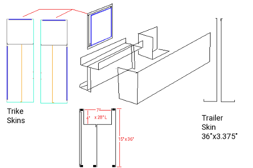 Adding metal skin:
Sheeting panels:
- Inside panel @ basket 46"x15" bent @ 8"
- Wheel well 23.5"x28"
- Upper storage 8"x28"
- Outer storage 36"x16"
- Equipment 8"x 31"
- Equip Front 8"x15"
Doors and covers:
- Battery lid is 28"x8"
- Storage door is 10.25"x26.5"
- Electronics Door at the front is 13.5"x6.5”
 The idea here is that the back will have a cover over the battery compartment 8"x 24", and solid top 12" towards the front. Solid Back 8"x15" bent and running next to the basket all the way to the front. The outside will be solid along the 36" side and bent to form the front 8" width. Under the
battery area we can either form a piece 4" down at 8"x 28" with 0.5" lip to secure it front back and sides with an 11" x 28" panel between the wheel well and the storage that raps under to seal in the storage area, or I could make piece 4" down
bent in 4.5" and bent down 11" then bent under 3.5" as one piece with a 4" x 3" piece making the rest of the battery box as shown. At the electrical compartment separation, we would have an 8" width by 15" height that raps under to provide the bottom of the electrical compartment. The 26.5"x
10.25" door and 13.5"x6.5" door would be designed to inset into the panels 0.25" for a flush fit.
The idea here is that the back will have a cover over the battery compartment 8"x 24", and solid top 12" towards the front. Solid Back 8"x15" bent and running next to the basket all the way to the front. The outside will be solid along the 36" side and bent to form the front 8" width. Under the
battery area we can either form a piece 4" down at 8"x 28" with 0.5" lip to secure it front back and sides with an 11" x 28" panel between the wheel well and the storage that raps under to seal in the storage area, or I could make piece 4" down
bent in 4.5" and bent down 11" then bent under 3.5" as one piece with a 4" x 3" piece making the rest of the battery box as shown. At the electrical compartment separation, we would have an 8" width by 15" height that raps under to provide the bottom of the electrical compartment. The 26.5"x
10.25" door and 13.5"x6.5" door would be designed to inset into the panels 0.25" for a flush fit.
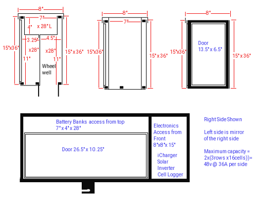
The upper frame has a Battery compartment 4" deep x 28" x 7" at the back and an electronics compartment 8"x7"x15" at the front, Wheel wells sit at 4.5" wide x 28"Long next to the basket, and a storage compartment 3.5"x28"x11" at the outside. Other side gets same measurements for panels only reversed.
On the lower frame, We can mount 2 pillow block Bearings at the outside edge. Slide a solid steel rod at 1" diameter through the pillow block through 3 sprockets and
into the other pillow block. Each of these will have a set of set screws to secure them to the rod. In this way we can assure positive alignment between the sprockets and the rear sprockets at the wheels and also with the center crank drive sprocket. At 23" on center will be our frame section to secure the front of the trike at the seat down pipe. Angle is yet to be determined. The top will be 10" between the seat down pipe and the rear frame. The height of this will be 15" to match the rear assembly. We do know the seat down pipe is 1" so a steel 1" 'U' (ID) will fit around the down pipe with 3 x class 5 bolts going through the down pipe to secure it. Top and bottom braces will prevent twist between the mount and the
down pipe.
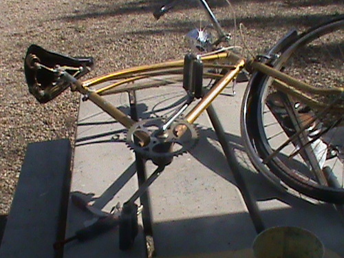
First bike acquired
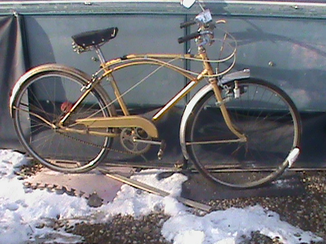 The Bicycle would has:
- 17" Seat down pipe to sprocket ... OK
- 26" Wheels with tires ... OK
- > 1.5" tire width ... Tire width 1.75"
- Front Hub spacing > 3" ... Hub spacing = 3.375"
- Axle mount length .... = 5.25"
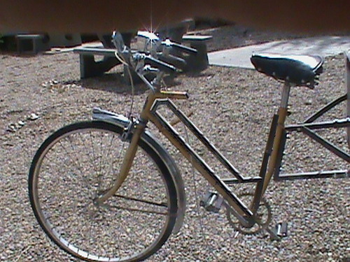
This first bike is a 3 speed in good shape. It has all the necessities 17" Seat down pipe, 26" wheels, and a straight frame. Equipped with working front and rear brakes, a two beam single headlight, mirror which we can use in the build.
The top of the seat down pipe sits only 28.5" and the seat bottom is 31.5" our back section top of frame will be at 31.5" so we are fine with 12" down
pipe to frame support. Due to the angle of the seat down pipe, the seat will overhang our mount by 5.5" which is also very fine. Under these specs, the bottom will be 11.5" from our frame.
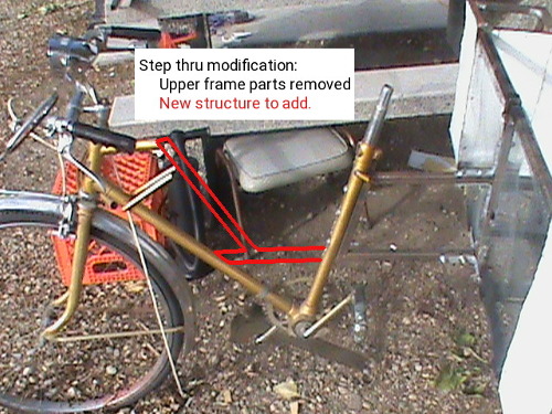
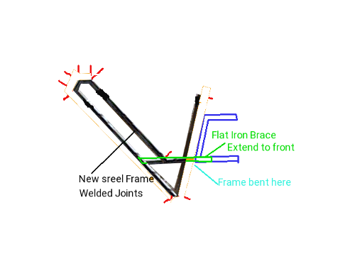
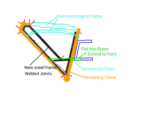
To use this bike for the front assembly, we need to remove the top bar, side supports and add a support from the lower 12" frame section extending to the front forks for a more usable step thru design. The top might just be long enough to fit the lower support for this purpose. The rear wheel well fender can be re-used for the trailer on one side. So now we just need another bicycle to complete the structure.
Actually, all we need is just the rear wheel and fender and front wheel to make the Trike and trailer complete.
Time for measuring
With an actual bicycle to work with we can now measure things and set the values for making the rear assembly.
- Tire width front 1.75"
- Tire diameter front 26"
- Wheel Hub front spacing 3.375"
- Wheel axle front 5.25"
- Tire width rear 1.75"
- Tire diameter rear 26"
- Wheel Hub rear spacing 4.5"
- Wheel axle rear 6.625"
- Pedal sprocket diameter 7.5"
- Rear Gear diameter 3"
- Pedal movement radius 8.5"
- Seat Down Pipe 17"
- Seat height from ground 35.5"
- Seat Down Pipe angle ??
- Front fork Pipe angle ??
- Top pipe length
- Front Axle bolt diameter 0.375"
- Rear Axle bolt diameter 0.375"
Second bike options
With this arrangement, we just need a second bike for the needed Front wheel (for the trailer) and the Rear wheel with fender. We should also get the second rear brake.
As an alternative we could just obtain the two tires with wheels and fender and cable brake unit. I am finding a difficulty in sourcing just the parts. Fender found are
in front/back pairs for $50 to $200, Pull cable brake calipers seem to be about $20 plus the cables for about $6, Standard front wheel without tire seems to be about $42 plus Tire about $17, Back coaster brake wheel is $72 plus tire at $17. But and there is always a but, mixing a coaster brake with 3 speed hub is problematic. Obtaining a
rear hub wheel has 1000's of choices. An electric Trike should have the ability to have electric brakes but such was not found, they are all manual as cabled pinch pads, or manual drum brakes or manual disc brakes. Bummer!
Second bike donated to the cause.
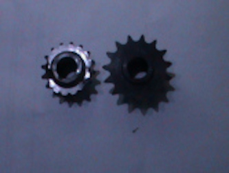
A second donated bike made some serious changes to our plans. For starters, it had fat 2" grip wheels at 24" not the original planned 26". The front wheel was quick disconnect and the rear wheel was equipped with a 7 speed sprocket and a 2 speed front sprocket. To use such a bike I decided to attach the dropouts for the rear wheels as changeable. This means I can at a latter date go with 26" wheels if desired. I would drive only one rear wheel and use the front wheel as a rear wheel in idler mode. For manual pedaling I have a choice of which of the 7 sprockets to use. The sprocket chain itself is 3/8" instead of the 1/2" chain needed to mesh with the crank sprocket from the first bicycle. All this means is that when I employ the drive axle, I need a 1/2" 16 tooth sprocket to mate with the front drive gear and a 3/8" 15 tooth sprocket to mate with the drive wheel.
Rear assembly construction:
Faced with delays and other obstacles meant there needed to be compromises. Funds for the project were expected at $1689 over the year and became a mere $296. The cost estimate for material and welding came in at $500 for welding and $359 for materials just for the trailer and trike rear frames. The Trike would be made originally as a pedal version and latter to a full battery/solar/charger e-Trike. Due to delays in getting the project started and lower money available, it was decided to have the shop supply the square tubing and drive line components and use riveted custom brackets to make the frames. Each rivet has a shear stress of 150 lbs so in theory with two to five brackets at each joint and 4 rivets per bracket it should yield 300 to 750 lbs of shear at each joint. The overall weight limits of the rear frame is 1400 lbs and 2" x 24" Bike tires have a GVWR of 2400 lbs. More than a little overkill here as the trike is meant
to carry 4 20lb propane tanks as its heaviest load, plus 100 lbs of battery and electronics and me (220lbs). Because 20 lb propane tanks are 40 lbs full we are at a total of 480 lbs. Our tires can support 150 lbs of frame + 480 lbs of load (1/4th of 2400 max). Our frame can handle the weight too 630 lbs ~1/2 of 1400 lbs so we are good to go.
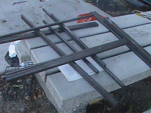
First things first. I ordered the square tubing as 25 pieces of 4' x 1/2" square tubing and immediately found that I could only obtain 3/4" or 1" square tubing not the intended 1/2" tubing. For my purposes this is not serious. Dimensions will have to be rearranged to compensate so that the total width remains at 46" and the basket of 30" width. Surprise surprise! Where I planned to cut all the 25 pieces to exact lengths and use the excess to make the uprights from the lower to upper frames, what I got was 23 pieces cut to exact lengths with no excess.
This presented me with new set of problems. The shop explained that doing my project they supplied the metal to the original planned lengths and due to lack of stock did their best and they are too busy right now to undertake more. The original plan was to construct the e-trike in April before they entered their busy season, have them weld it all. Now I would construct it with riveted custom brackets and weld latter.
Having less metal to work with meant some radical changes which actually turned out for the better.
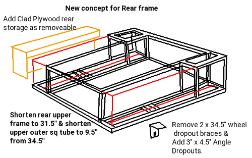 I modified the upper frame to enclose the Battery and Electronics compartments while keeping the basket frame. The two storage area's over the wheelwells can be removed for sevicing the brakes. I changed the 15" uprights to 13.5" and adjusted demensions to compensate for 3/4" material instead of 1/2". I aso lost the inner wheel bracket support so I will need to extend off the outside lower frame for wheelsupport.
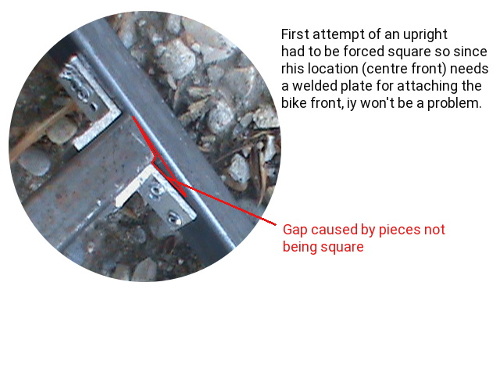
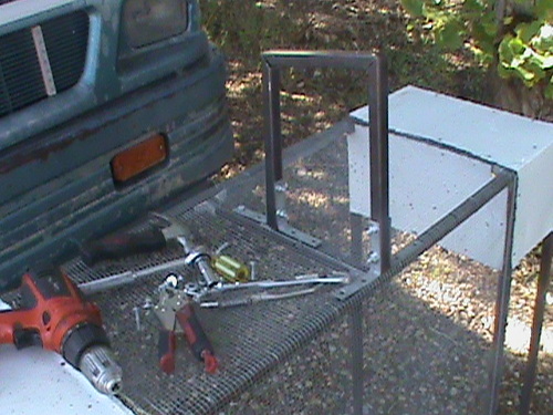
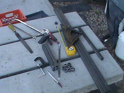 Using the layout above- right, I first trimmed the main pieces to exact size as some were longer by as much as 1.75". Using a piece of 1x1" 'L' channel I then cut by hand 120 brackets
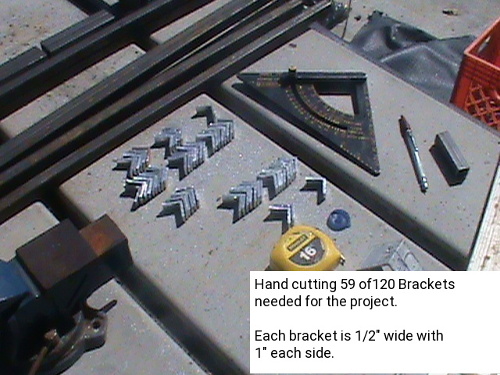 and drilled 4 1/8" rivet holes in each.

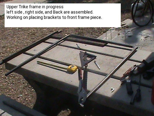
On the left we have the assembled lower frame 36" long by 46" wide with provisions for 8" sprocket/wheel wells on each side and a 30" wide basket. To the right we are making the upper
frame. The adjustments made to compensate for using 3/4" tubing instead of 1/2" tubing affects the length pieces not the width pieces. So for the bottom frame we have two 46" lengths and four 34.5" instead of six 35" front to back lengths.
The top becomes radically different. It still has a width of 46" at the front, but the back is shortened to 31.5" and instead of four 35" front to back pieces it now has two 34.5" lengths.
At the front will be two 8" x 8" sub frames to make the electronic and battery compartments.
There are few mistakes here that are not critical. We need to handle 640 lbs and according to two different engineering computations one says maximum load is 1400 lbs but written on their site as 1400psi
and due to using rivets it is safe to 60% of that limit. The question is raised as why is a welded structure designed for 1400 lbs only safe to 1200 lbs? Secondly, 1400 lbs load is far cry from
1400 lbs per square inch (1400psi). The other computation site gives the results of 1480 lbs for maximum load when welded and 960 lbs using rivets.
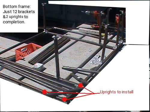
So placing the uprights onto the lower frame we are close to having the bottom finished. On the picture I incorrectly said only two uprights remained to be installed but as you can see there are three to do.
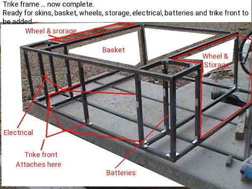
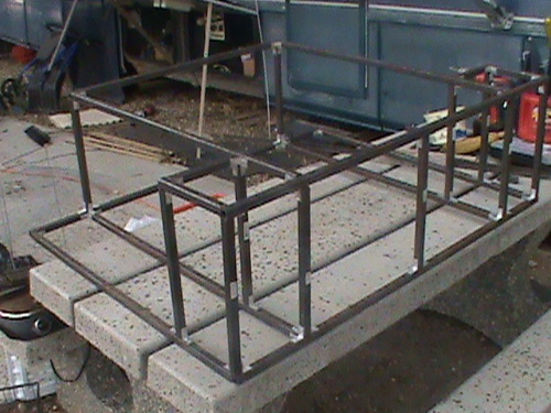
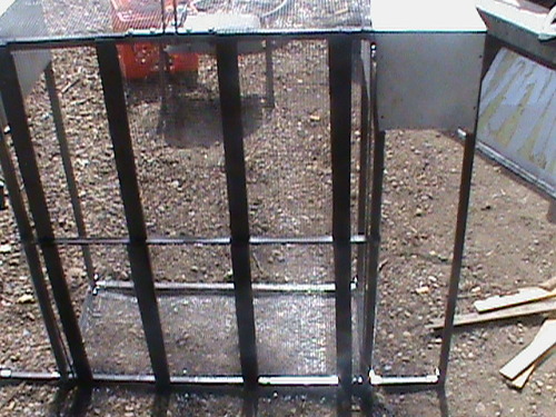
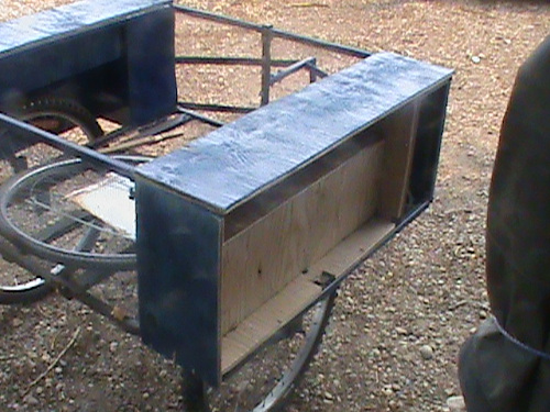
Rear Frame assembled:
Below we have the constructed frame for the rear of our tricycle. First we have the image with the highlighting of the features. It meets all the specs of our design with 4.5" x 28" x 10.5" wheel provisions, 4.5" x 28" x 5" battery packs above the wheels, 3" x 28" x 14.5" storage either side, 30" x 36" x 14.5" basket, and two 8" x 8" x 14.5" compartments for electronics and batteries. In essence we could have 90A @ 48v of batteries to triple our distance although I will be happy to have one 30A 48v pack.
Rear Skins construction:
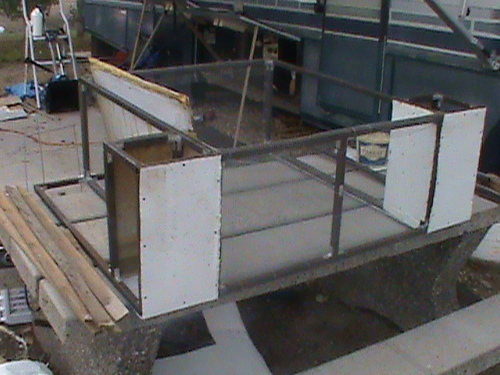
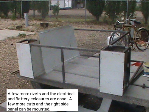
The Electrical and Battery compartments need to be enclosed. I made a valid change to the plans by deciding to move the front compartment doors to the sides.
It simplifies making the side compartments as you will see. Using the repurposed metal skin from an old compact fridge I made two 8" x 22.5" pieces and riveted them on the front and bent around the bottom. Two more pieces 14.5" x 16" were formed to enclose the back and inside side of the compartments.
We have the four angular views of the rear frame with enclosed compartments. The inside skins have to wait till the rear brakes are installed. These last inside skins also need to be removable to service the brakes.
Front of Trike construction
At this point we want to start preparing to add the front of our trike. So first we need to remove the back wheel section of the bicycle. A hacksaw made short work of cutting the back aluminum frame of the bike. I fashioned an attachment frame to connect the trike front to the rear assembly. It mounts to the back using four 2" brackets. two go on the center upright and the other two to the bottom frame.
It's been a long process dealing with very hot days, lots of sawing steel, occasional rain delays and all those 1/2" wide brackets. But it appeared the project was moving ahead. In retrospect, the shop said a cut and welded assembly was
estimated at four hours and manually cut and riveted assembly took 30 days ... wow!
Reflections
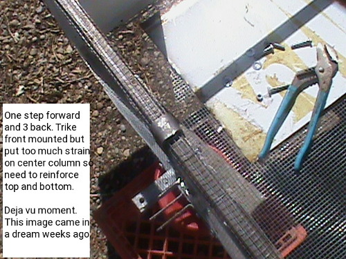
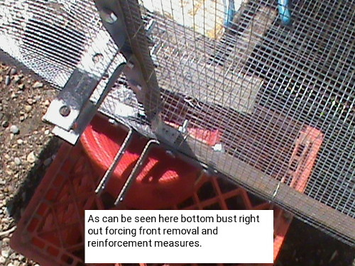
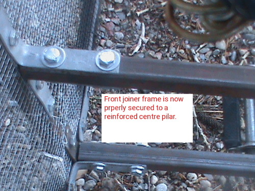
The night after I installed the center post for mounting the front of the trike to the rear, I had this recurrence of a disturbing dream of attaching the front of the trike the rear and the center post busting out at the bottom frame and having to reinforce the post with straps top and bottom. The image shown is exactly what I had in my dream! So when I did attach the front to the back, it was no surprise that the strain did in fact break this center post free.
Being bolted together I removed the front section and joiner off the back and took steps to put two 'U' shaped supports going over the top and bottom frame rails and secured solidly onto the center post.
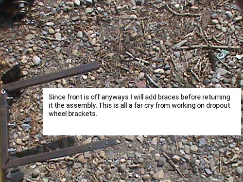
This set back kinda delayed my intention to put the wheel dropouts into place right after attaching the front to the rear assemblies. Since I have the front off again anyways, it is an opportune time to also add the side bracing top and bottom before putting the front back on.
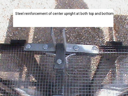
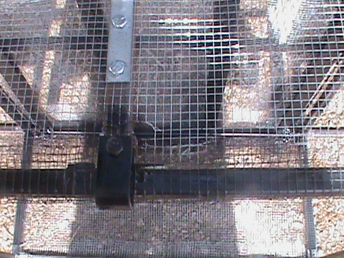 As just mentioned above, I installed two 'U' shaped metal straps top and bottom and bolted to the center post. Latter I will weld the center post so there will be no more issues.
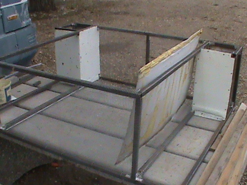
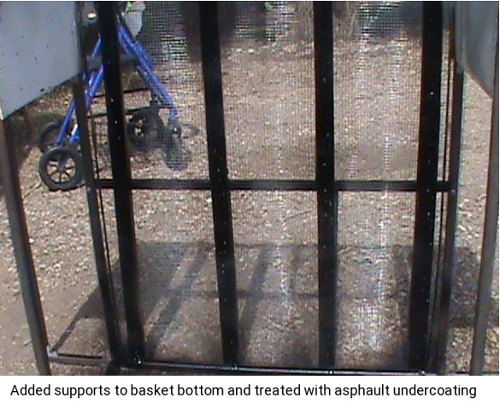
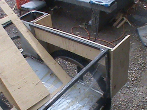
Rear Basket assembly construction:
For our basket we will have a wired mesh front and back and on the bottom. The basket will be enclosed on the sides with metal skin and have a reinforced bottom with a center support and 4 wood straps. The intention here is to allow rain and snow and air to pass through the mesh rather than collect in the basket or add wind resistance.
 The mesh was laid over the upside down frame and wrapped around the inner side rails, front and back uprights and front and back top rails. Using more thin wire the wrappings were stitched.
Here we see the reinforcing done. There is a center support and 1/2" x 1.5" x 34.5" slats mounted either side of the wire mesh. I took the opportunity to coat the slats with rubber undercoating. The container said rubber asphalt undercoating
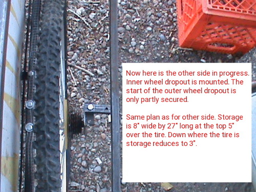
Wheel dropouts:
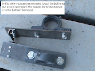
Hand bending metal into tight 90 degree straight angles is not so easy so I decided to use 1/2" 'L' channel bolted to flat iron plates to make the dropouts for the wheels and for the axle bearing blocks.
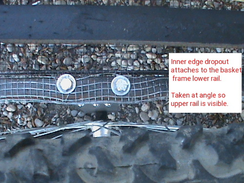
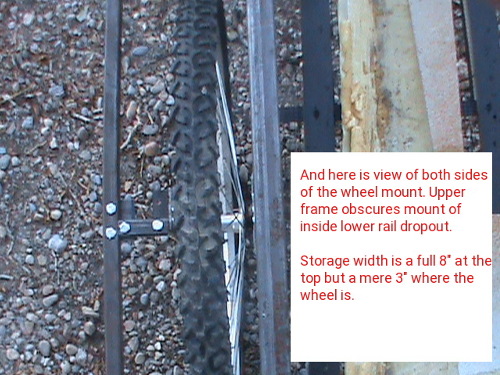
.25" bolts secure the brackets to the frame and 3 3/16s bolts secure the brackets to the plates. 5/8 holes centered at one end of each plate provide mounts for the wheel axles. These holes are then made into slots to make the dropouts.
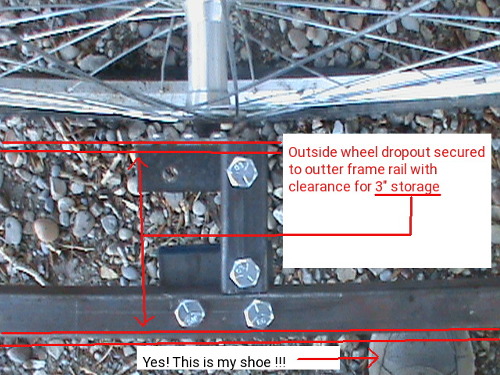
For the outer mounts, we lack a mount frame so at the wheel axle we make an extension off the outer frame consisting of a plate some square tubing and the dropout bracket.
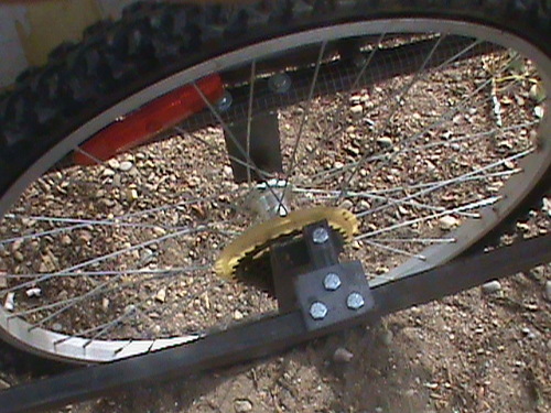
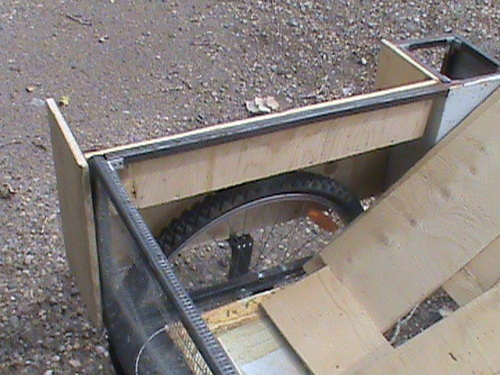
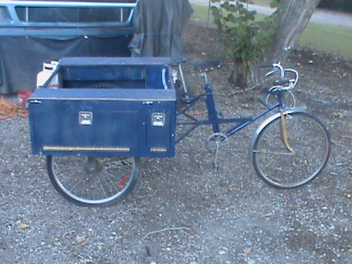
As can be seen, this worked quite well to mount the rear wheels and we have something that now looks like a tricycle!
THE TRICYCLE: Push mode
With front end and wheels attached we have a tricycle that can't be used other than by pushing it. The angle is wrong between the front and back so the front of the back section is not even with the back of the back section. As a push vehicle it worked very well. I was amazed at how easy it was to push and control.
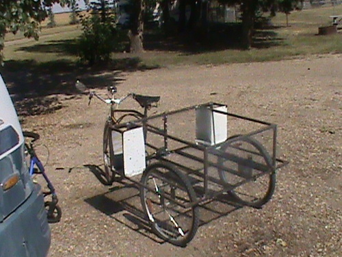
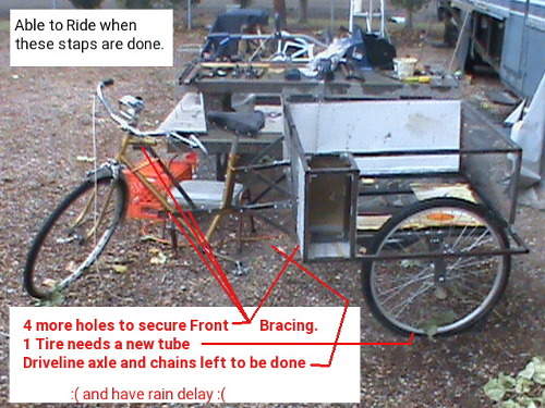
As seen in the last picture, it is a Tricycle with future provisions for Battery, electronics, and storage. It still has front bracing, driveline drop downs, back to front section level adjustment to be done.
Once the side bracing is in place, it would be prudent to weld this to make one rigid assembly. The seat down pipe is secured to the back by 3 bolts into the attachment frame. As I said earlier the back section is not level, so I will need to remount the front about 3 to 5 inches lower. In a short while you will see that I made an Oops with regards to this. An Oops I might add that could have been prevented had I made the change before testing out sitting on the unit.
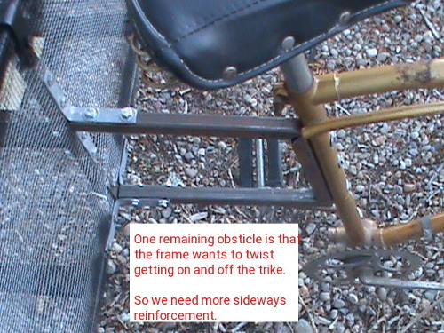
Making a step through
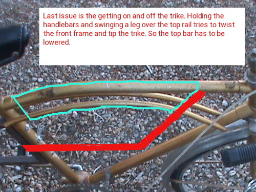
Here is the plan for making a step through frame on our Tricycle. In true fashion I tried to run before I learned to walk. It's a but and there is always a but situation. I cut out the section of frame
intended to be removed. But and there is always a but I returned the seat onto the seat down pipe and immediately proceeded to see if I could step through the frame without it twisting. I didn't intend to actually sit on the seat but as luck would have it did just that! The bottom of the rear mount frame at the seat down pipe abruptly bent and in no small way either. More on this later.
Advance planning:
When the weather is uncooperative provides time to think of upcoming and future parts of the project. I will discuss braking, lighting, and the windshield plans. The first of upcoming/future parts is the concept of having brakes on the tricycle.
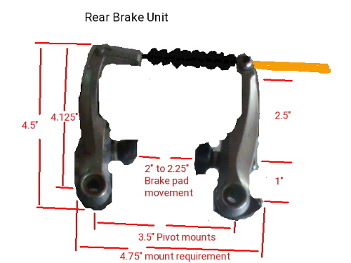
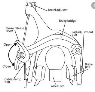
Two types of brake are used. The 3speed had a top pull and retained for the front brake and as an mediator to transfer brake handle to two brakes at the back. The Back brakes come from the second donor bike and are of a side pull type shown. With limited space in the wheel wells at the back the top pull take less space than the side pull.
The front remains as is. The back brake line from the brake lever at the handlebars runs down the front frame to the repurposed side pull brake mounted on the joiner frame. The joiner frame is modified to pull two cables going to each of the rear wheel top pull brake calipers. Mounting of all 3 rear calipers needs to be worked out.
Look into other technologies
Other technology might be able to shed light on my concept. For years there has been a move to automated aids primarily targeted at the mobility impaired using
automobiles. So I looked for the leaders and came back with undeniable source. aevit automated vehicle integration technology. This company is world class leader in technology to enhance mobility impaired individuals to control a motor vehicle. It starts with the primary functions of steering, acceleration and braking. Then further
modification is used to add the secondary functions of turn signals, wipers, radio,
phone, lights, horn and others. Basically any car or truck may be adapted without changing the original primary and secondary systems. As such, a vehicle can be operated by normal factory control systems or by the adaptive systems.
As adaptive systems go, there are a wide variety of add-ons. Automated door closers, wheelchair ramps and lifts provide for entry / exit needs. Various hand controls types are introduced to accommodate the special needs with primary focus on the three primary functions. Steering by the factory wheel, wheel with suicide knob, and Joystick in a
number of designs to control servo's. Electronic Transmission shift coupled with a lever or joystick provide for direction movement (fwd/rev) , Acceleration in the set direction and braking. With the Joystick you can achieve steering and acceleration and braking all in one. For a vehicle these are a major step forward from the simple lever style push rods that merely pushed the gas and brake pedals using a floppy lever mounted at the steering wheel.
Power servos are controlled by Joystick and control circuit to physically turn the wheel for steering, regulate the amount for gas or brake to apply. Simple switches select the gear and direction of the transmission.
But and there is always a but, we are doing an Electric Trike. It needs things to be light weight, steered by the rider, Accelerated and braked by some means. Typically, the right handle grip will have a thumb throttle or a twist grip throttle. Left and right brake levers control the front and rear brakes independently. In a car the brake pedal puts 60% to the front and 40% to the rear for braking, but bicycles can have 0-100% applied to
either or both. This means if the front brake locks up you are going to stay in motion
and suffer significant damage as you get tossed forward.
Standard bike brakes are either cable, or hydraulic. Cables stretch, fray, and snap. Hydraulics leak and get air bubbles. Calipers are either rim, disc, or drum. With E-bikes, regenerative braking and resistive braking were added. This adds up to 8 styles of braking for an E-Trike.
They each have there good and bad (15kph - 0):
- Cable-Rim Poor stopping, rapid heating, 3-4 car lengths
- Cable-Disc Better stopping, semi-rapid heating, 2-3 car lengths
- Cable-Drum Better stopping, /semi-rapid heating, costly, 2-3 car lengths
- Hydraulic-Rim Poor stopping, rapid heating, 3-4 car lengths
- Hydraulic-Disc Better stopping, semi-rapid heating, 2-3 car lengths
- Hydraulic-Drum Better stopping, semi-rapid heating, 2-3 car lengths
- Regenerative Poor stopping, rapid heating, 6-9 car lengths
** may overcharge the battery **
- Resistive Poor stopping, major rapid heating, 4-6 car lengths
Heat is the problem. hot brakes wear the pads fast, warp Discs, deal poorly with moisture. With Re gen and resistive braking you also get an issue of enormous reverse torque that can twist forks, strip axles and dislodge the wheel from the bike.
So in an E-Trike we need several things to happen. Firstly, we need to cut motor power or switch to re gen when brakes are pressed or throttle is released. The
controller actually should do this already if brake handles have motor cut out switches.
Secondly, we don't want to short the motor windings as in resistive braking as this
damages the motor and creates heat more than it provides more stopping power. Thirdly
we need standard braking run from the brake levers to all 3 wheels. It has become a
bigger topic than I had planned for.
At the onset, I figured to have the front rim brake stay as is and run the rear brakes in a 'Y' configuration where the right brake handle pulls a cable to mid mounted caliper which then pulls a cable to each rear brake caliper on rim brakes. The front
electric wheel has provision for Disc Brakes if fork clearance is ideal. The rear wheels will need to be changed to ones that have disc brake provision as rebuilding the hub is expensive. And this still leaves me with trouble prone Cables or optionally hydraulics with cable activation.
Our E-trike is all electric except for braking so maybe we need to improve to electric braking. For this we need Twist grip accelerator pot or lever action pot to control the amount of pressure to apply electrically to a brake actuator. The Actuator can then apply push or pull action to the very short Cable at each wheel. Under such a system, the handlebar brake lever turns a potentiometer with auto return spring. A magnetic reed switch or hall-effect signals when brakes are applied. 4 wires from each brake lever go to a control circuit. The control circuit sends a brake applied signal to the E-Trike motor controller and the pots convert the resistive value into Voltage of a varying amount that powers the actuators at each wheel. Thusly, either brake lever can cause 3 wheel braking. Changing the voltage at the front and back actuators can allow for proper 40%/60% braking. A Pull actuator then pulls a short cable the distance based on the supplied voltage and the cable can now operate the pull caliper of a cable or hydraulic rim, disc, or drum brake.
In retrospect, the maximum force on the lever that a person feels comfortable at gripping for a long duration can be as little as 1-2kg for a child, 3-6kg for a woman and 5-7kg for men. This new pot type brake lever is highly sensitive with 0.2kg - 0.4kg so you do not get the back force of cable adding tension. The actuator is available with 10N - 2500N which compares with a typical man that has 7kg = 70N. As such you don't need a very powerful actuator to provide the cable stopping power of 70N applied to the calipers. This means we have replaced Manual Cables of 4' to 10' with electrical wiring and the actuators can mount as close as 4" from the calipers at each wheel. However for our purpose a mid mounted actuator still removes 5' of cable, cable routing, and
modifying a caliper into a 'Y' configuration.
So in normal E-bike design you have throttle, motor cut off on brake levers, battery, and motor control. Brakes are manual via brake levers and cable driven. Lights, horn, charging, and heads up display are after market add-ons. Using after market add-ons it
is possible to implement turn signals by wired connection or wirelessly, but these usually have a self contained battery that is low in power and lumins. Headlights can have built in horn if your lucky and of course their own activating switches. The brake lights are generally added by again wired or wireless with again internal battery and yet another switch. Some controllers have a display that gives speed, odometer, temp, battery status, but most do not. After market E-bike displays exist that mount at the
handlebars with wired or wireless speed sensor down at the front wheel. Our handlebar can therefore become quite cluttered with Throttle, Key switch, two brake levers, Left/right turn buttons, Headlight switch, horn switch, brake switch, Info display. We need all these but there has to be a better way.
Above we talked about making an electric form of braking. Using a lever Potentiometer with micro switch or reed switch, we can have the switch do dual duty to both cut motor power and turn on the brake lights.
Lights
Making custom lights for turn signals, markers, and Brakes allows us to use our main battery and high lumin LEDS to give improved performance. A custom turn
signal/horn switch places both in an easy to access location. Headlight, hazard flash, Key switch, display can be combined into a single unit with less demanding space requirements.
A lot of lights for bikes with handlebar switches for on/off/turns are either Bluetooth or wifi functional. These have internal battery for operation instead of direct wiring. As batteries wear down the lights become dimmer progressively so really not a preferred functionality. For our electric Trike we have a 30A 48v battery bringing 48V to the handlebar Key switch so supplying 48V to our lighting controls is not a problem and 48v LED lights for our signals headlight and brake lights are not a problem.
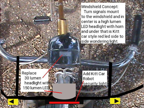
This brings us to neat modification. A regular 6v lamp as the donor bike has is only 30 lumens (dim) and at 48v we can go with 150 lumens (super bright) LED and add to that a simple robot light simulating the kitt car or cylon roaming light. In the future one could tie this light into a sensor and security system and people can be chased away with the feeling they are being watched (which they would be!). As we travel, the futuristic roaming red light up front on the windshield moves back and forth but when the Trike is parked and shut down, the roaming light goes out.
As progress develops, we can go further into our end game plans for braking, lights, and control.
Windshield
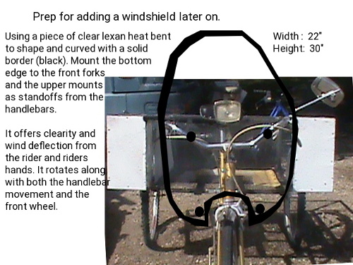
Next thing to think about is the windshield. We need it to rotate with the handle bar movement, support turn and marker lights, shield not only the face but also hands.
An OOPS! :
Winter prep is rolling in fast! There are leaves falling all over and they need to be cleaned up as well as making things winter ready. So my time is getting shared now between leaves, winter prep and trike progress.
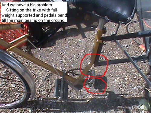
Sitting on the trike before we were ready was NOT a good plan. We had installed the upper twist preventing brace on our front to back joiner. The first picture shows the damage, the second one shows an idea to correct the bike in part. First we need to remove the front and straighten it, then build a sub frame, put in the lower brace and move the joiner frame down lower.
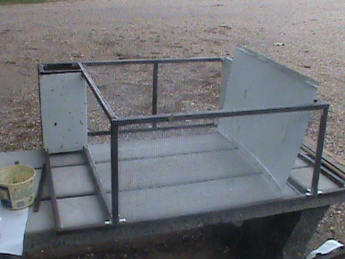
Side compartment construction:
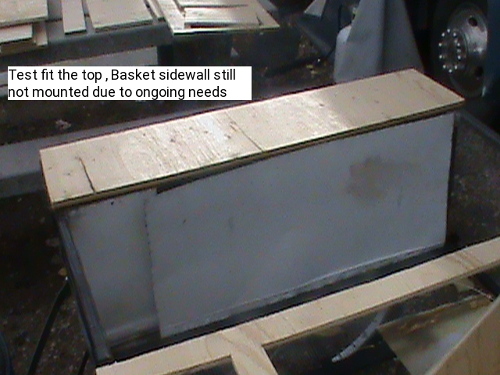
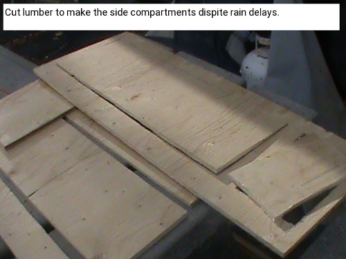 It's a race against time and the weatherman! To make the side compartments, I cut two 8.5" x 36.5" tops, two outer side panels 36.5" x 14.5" with the doors panels cut out. Then cut two each of front, back, storage bottoms, inner walls, upper storage , and basket side upper frame pieces.
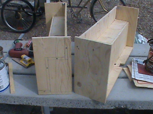
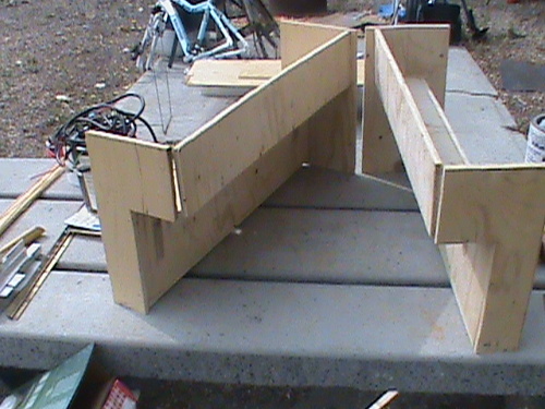
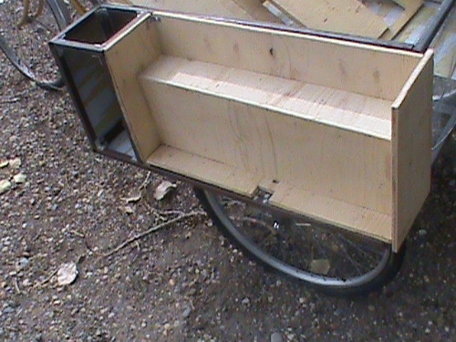
 Here we have the side compartments ready to be fit into place. As can be seen they form a kinda fender around the wheels. Ideally, it was intended for all surfaces to be cladded with metal but this didn't happen this year at least.
You will note that the side frames have notch outs where the wheels dropouts are. This needed to be done so that the frames could clear the mounting bolts which otherwise would prevent the compartments from sitting flush. On the trike frame itself, some adjusting is needed to make sure the compartments fit flush at all points. The compartments will secure to the trike frame using four bolts per compartment. Two are placed on the top basket bar and Two on the lower outer bar. The side door panel screws onto the compartment and into the front Battery/electrical compartment frames. And lastly, The compartment tops screw to the top of the compartment and also to the front Battery/electrical compartments. This provides us with a solid sealed side compartment assembly. Piano hinges secure the doors to the outer side panels and cam locks provide secure closure.
The dry fit has some tweeking to be done but this has to wait till spring.
Spring has sprung and grass is griss
We left off with a lot of uncompleted jobs on the trike. We had all winter to think about what needs doing and how to do. I began by removing the front section for straightening. Removed the rear compartments and made the back section ready for the drive axle to be added. I had one rear tire that would not hold air so I replaced the tube and have a happy tire again.
The driveline system:
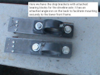
A change of pace was in order. I would have to remove the front section and reinforce it after straightening it. So since I would have the front off anyways, why not install the drop downs for the axle assembly while I'm at it. These drop downs have a piece of 1/2" 'L' channel up at the end that mounts to the lower frame. Two i/4" bolts mount through the lower frame into the 1/2" 'L' channel and 3 x 3/16" bolts mount into the lower facing frame and also the 'L' channel for stability. The pillow bearing blocks mount on the drop downs as shown. Between these pillow blocks go two pillow hubs with their set screws the anchor into the pillow blocks. A steel axle shaft fits into the pillow assemblies and on this axle goes the shown sprockets. These sprockets consist of the sprocket and a hub welded to the sprocket. Placement of the sprockets must line up with the drive gear at the crank and drive gear at the wheel. Set screws on the sprockets lock them in place.
The Drive Axle
My plan for the axle was thwarted by two braces I added to stabilize the trike front. A new plan was needed. The bracing took considerable effort to get it in place and now prevents the drop brackets for the axle pillow blocks to go on. Plan two is to place the pillow blocks horizontal to the rear frame at the inner basket rails. With 1" spacers between the pillow block and the rails there is enough room for the chain drive to work. So we remove 2 drop plates and 2 2" brackets and add 4 x 1" square tube spacers. Our square tubing frame is 3/4" with 1" brackets affixed to joints. The bolts are 3/8". With all this in mind, our pillow block mount holes must be 1-15/16 from the front edge on either side. The other mount holes are 3-5/8 farther than the first set.
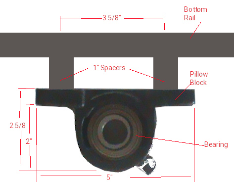
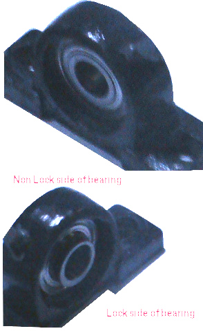 With the new pillow block location solved for it is time to add the bearings to the pillow blocks. One in the picture above is done. While the pillow block has a grease fitting nipple, it is not used as I chose sealed pre greased bearings. On the one side of the pillow block there are two grooves designed for the bearings to fit into the block and using a pry bar you rotate the bearings from horizontal to vertical against the guide grooves. The bearing must be rotated perfectly square with-in the block. The one shown worked great but the second one tried to rotate at an angle and resulted in it being punctured. Needless to say it has to be replaced at a cost of $15.00. The axle is a very tight fit. It needs to pass through one bearing, then a lock collar is fit on and the center sprocket goes next. I should point out that the bearings can go into the pillow blocks with the locks either on the inside or outside. I chose both to be on the inside with the pillow blocks orientated to meet this specification. So we add the second lock collar before feeding the axle through the other pillow block. With a 36" axle and 1.5" pillow blocks centered on the inner basket rails, the axle is flush on the left side. This means that at the other end we have 36" - 30" basket - 1.5" (2 times .75" inside bearing blocks each end) = 4.5" for servicing the outer sprocket.

The lock collar is tightened in the direction of rotation. In our case, the main pedal sprocket rotates clockwise which turns the center sprocket clockwise and the shaft clockwise. At the outer end the sprocket likewise turns clockwise to turn the wheel drive gear clockwise (forward motion). When the wheel is free wheeling, no pedal motion is used and so the sprockets do not turn and the shaft / axle is idle. To put the locks in place, move the collars to the bearings, and rotate them in the direction of travel till they seat tight. Using a hex tool tighten down the set screws. We can't line up the center sprocket because the front section of the Trike is not yet re-attached but we can line up the outer sprocket with one of the driveline gears of the wheel cassette. Smaller sprockets turn the wheel faster per revolution of the axle and larger sprockets turn the wheel at a slower rate. When you have chosen the desired sprocket use an Allen wrench to secure the sprocket set screw.
I hope to re-use the driveline chain from the second bike by shortening it and using a chain link. Because we are not going to be switching drive sprockets the trike will act as a standard single speed bike and will have no derailer. A single speed bike chain requires about 1/2" up and down movement at the center point between the sprockets. It might become necessary to use an idler to add tensioning but we will see.
Rear brakes
 There are tight constraints in the back wheel wells. Raw space of the wheel wells is 28" L by 5" W by 8" H. From the basket edge to outer frame is 8". The wheel drop outs are set 1/2" in from the inner frame and 3" in from the outer frame. 8" - 3.5" = 4.5" for the wheel. With the compartment in place, there is 5" max for the brake mechanism in width and 8" in height. On the original brake / frame it actually fit over the wheel at an angle.
24" rear wheels (12" radius) with 4.5" drop-outs places the bottom edge of the frame 16.5" from the ground and taking into account the frame is .75" thick, leaves 6.75" of wheel inside the wheel well. The rim is 0.5" and the tire is 1.5" to make the 2" of area of concern for braking. The bottom edge of the brake pad must rest 4.75" above the bottom rail if the brake mechanism is mounted vertical (perpendicular to the frame). As you move away from 90 degrees, the brake pad rotates forward and also closer to the frame.
I cut the brake mechanism from the rear assembly of the second bike frame. It has two parts. A solid 'U' shape mounting frame 6.5" H x 4.5" W x 1.5" D and brake levers 4.75" H x 4.5" W x 1" D. The overall assembly will occupy 6.5" H x 4.5" W x 2.5" D. Placing one leg of the 'U' mount frame on the inside rail and the bottom of the 'U' to a bracket off the back of the electronics bay or the battery bay on the other side will accommodate the brakes such that they clear the compartments. Cabling will come out into the basket on the left and through the compartment wall on the right, feeding through the electronics bay to end in the front to back joiner section.
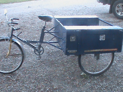
Installing the rear compartments
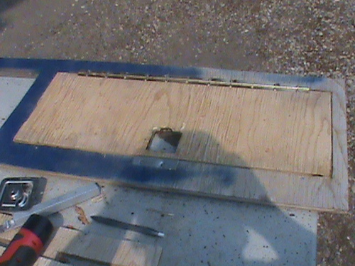
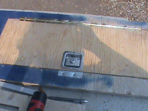
Our side compartments at the rear have a one piece door frame with two doors held on with piano hinges and embedded recessed keyed alike door latches. As luck would have it my paint ran out part way through the painting job. Using my Dremel with a variety of cutting wheels and determination I was able to fit the doors and latches into place. You will note that where the latches are I made metal strikers to facilitate a tight secure fit. In a perfect world, I have preferred to metal clad the the door frames and doors.
Nothing goes without a hitch! When trying to mount the side compartments, I first tried to use a tap-n-die with no success and had to switch to self tapping screws into the metal frame with better success. It took considerable pressure to get them in and had a tendency to try and pull right through the plywood. If I do it over, I would have pre drilled the pieces with better quality drills bits that don't snap, then tapped the screws into the metal an finished by then hand screwing the pieces into place.
The door frames were then secured to the compartments. I added 4 tie downs to the top of the sides so a tarp cover can be added to cover the basket and eventual solar panels. While I had the top covers and side panels off, I did pre wire for lights and electrical which is shown in the next pictures.
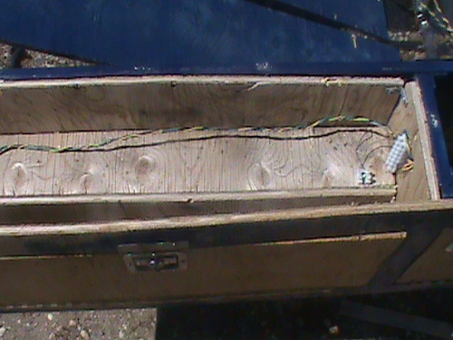
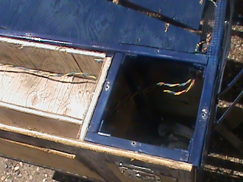
On the right side we have a 5 position barrier strip with GND-Brake-Right signal-Marker (-) - Marker (+), a 2 position barrier for side markers (-/+) and a 12 position barrier to handle lighting to both the front controller and the left side. Wiring passes through the electrical compartment and into a conduit to the front of the basket and into the battery compartment on the left side. This same conduit has 3 x 14:3 wires to the battery compartment and 2 (+/-) wires to the solar panels. A 5 position barrier strip inside the electrical compartment handles Gnd,+6v,+48v to the batteries and Gnd, +57v to the solar panels.
On the left side, the conduit enters the battery compartment and the lighting wires pass into the rear section with again a 2 position marker barrier strip and a 5 position tail light barrier strip. Ideally, I should also pass wires for a trailer but alas I didn't do this.
Restoring the front section
The front seat down pipe was carefully straightened. It had mount holes 7", 9-5/8", 11-5/8" and 12-1/8" from the bottom and taking into consideration for pedal clearance we can only lower the rear frame by 1" which is considerably less than the 2"++ I was hoping for. That rear brace support is once more in the way!
For maximum support against frame twisting, the lower brace must run from the bottom of the rear frame to the front edge of the frames joiner. Then for maximum support of the front frame against bending, it must carry forward to the front fork support. At the top of the fork down pipe we must brace down to the center of the forward running brace and add a solid steel support along the seat down pipe. The picture above left, is of the front reattached, and the right has the bracing put in place.
Two connected problems have to come to light in the design. The seat is higher than the handlebars which is not good. Since the vintage front forks don't support raising the steering bars, I need to lower the seat and or change the bars used on the front forks.
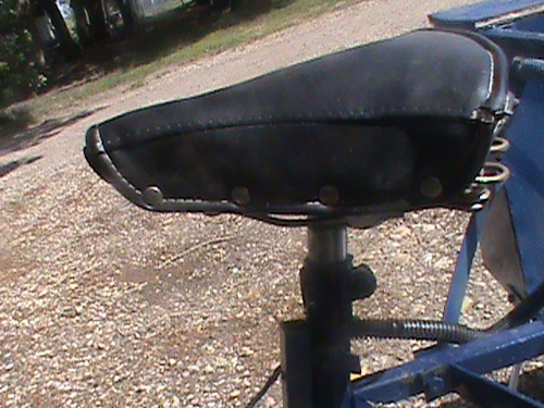
I removed the seat pipe and cut off 1.5" and lowered the seat 2" which improved the relationship considerably.

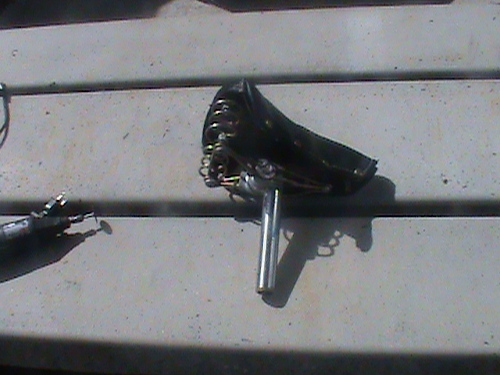
 I have ordered a new handlebar and seat which will look something like this.
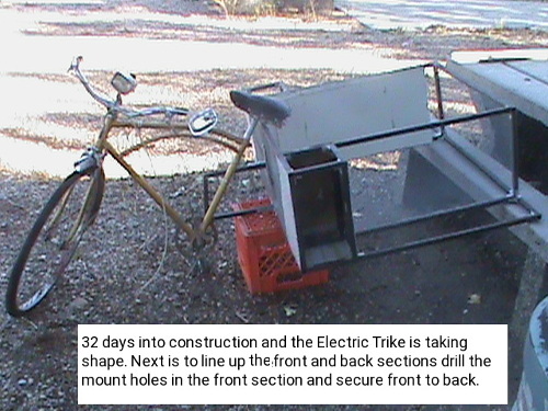
 And our Solar electric tricycle is taking shape!
We are now at a crossroad in the project. All
 the physical work so far is the same regardless of the drive method. But, and there is always a but. As is, I can just connect the crank set to the drive axle and have a manual only drive tricycle. The battery pack and or solar would service the brakes and lights. I can continue on with a front wheel hub motor and controller at 48v for a range of 80 to 144 kms with a maximum speed of 50 kph as long as the front forks can handle a hub motor wheel. I can change to a 24v front hub motor with a range of 60 to 100 kms with a maximum speed of 33kph. I can change to a mid drive motor with a change of the axle assembly also with a lower speed and range or as fate would have it use a donated old electric wheelchair drive system that in fact would offer 80 to 144 kms on a modified axle with a speed of up to 110 kph.
The last option may sound ridiculous simply because why would a wheelchair travel so fast. A standard wheelchair is rated for 8mph on 10 inch direct drive tires. The motors (two of them) drive the wheels from a 4800 to 5400 rpm dc motor with a controller that can drive the motors forward or back and convert high rpm to a lower 268 rpm through a worm gear transmition. On our application, we would replace the 10 wheel with a 7 inch sprocket and chain to a 3.5 inch sprocket at the axle and the axle would drive the rear 24" wheel. At maximum speed, 268 rpm becomes 537 rpm at the axle. This results in an effective speed of 38+ mph (63kph). We would need to govern the speed to 50kph by lowering the maximum rpm's.Moving to the outer smaller sprocket at the wheel would result in 76+ mph (126 kph).
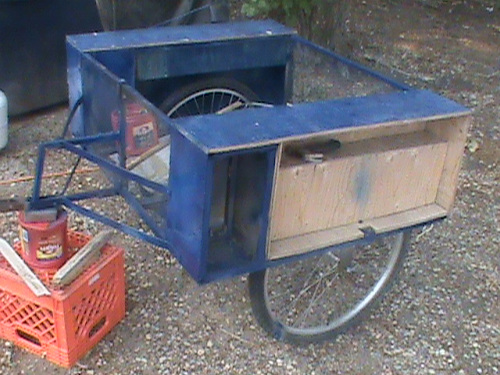
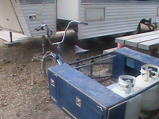
The final hurrah! I have an almost ridable trike ready for conversion to a fully electric unit.
In
 two years it has served well as a push tricycle to carry 5 propane tanks (200lbs) for refilling.
The rest of this book deals with making a trailer, The front controller with detachable computer, the rear charger, solar charger, and battery packs.
Bill of Materials
Section |
Item |
Estimate$ |
E-Total$ |
Actual$ |
A-Total$ |
Basic Trike |
bike 1
bike 2
bike 3
|
$0.00
$100.00
$100.00 |
$200.00
|
$0.00
$9.98
NLR
|
$9.98
|
|
With the changes along the way I was able to acquire 2 donated bikes and
reworked the design such that only 2 bikes were needed. The other bike had 24" fat wheels and became the rear wheels. One of
these wheels needed a new tube.
|
|
Trike Framing
|
0.5" x 48" Sq Steel Tubing (25)
20ga Metal skin ()
Welding $2/joint
120 cut
brackets
Compartment Locks (6)
Piano Hinge (8ft)
|
$160.00
$230.00
$120.00
$36.00
$12.00
|
$558.00
|
$195.00
$0.00
$42.00
$0.00
$9.00
|
$246.00
|
|
Building the frame took considerable reworking. Firstly, the .5" square tubing got changed out to .75" square tubing, and instead of getting
25pcs x 48" I only received 23 pcs cut to almost exact lengths. Welding was replaced by 120 cut 0.5" x 1" 'L' brackets and 480 rivets. A set of donated keyed a-like recessed door locks completed the framework.
|
|
Driveline |
1" x 48" Steel Rod (1pc)
1" Pillow Bearings (2pcs)
15T Sprocket (3pcs) chngd (2pcs)
Chain (15ft) |
$8.55
$25.18
$46.48
$50.00 |
$130.21 |
$38.95
$25.18
$30.98
$0.00
|
$95.21 |
|
The steel rod was much more
expensive than planned. We are only driving one rear wheel instead
of both so sprockets become 2 not 3 and the existing chains are
resized to work.
|
|
Brakes |
Brake F Caliper
Brake L Caliper
Brake R Caliper |
$26.00
$26.00
$26.00 |
$78.00
$966.00 |
$0.00
$0.00
$0.00
|
$0.00
$351.19
|
|
A little
reworking and I was able to reuse the brakes from the donated
bikes to facilitate the braking of the three wheels. The front
brake remained unchanged. A transfer caliper then fed the two rear
brake cables such that when the rear brake is applied it pulls on
the middle caliper which in turn pulls two brake cables to the
rear wheels that use the brakes from the second bike Now with
electric braking the front brake cable to the center is gone as is
the middle 'Y' caliper to be replaced with a pivot and servo.
|
|
Other
|
Pop Rivets
Class 5 Bolts (7)
Primer (3 cans)
Blue
Paint (3 cans)
Acetate glue
Epoxy/ resin 8oz to 16oz
|
$3.49
$4.67
3 * $6.95
3 * $6.95
$5.49
$12.78
|
$68.13
|
$3.49
$4.67
3 * $6.95
3 * $6.95
$5.49
$12.78
|
$68.13
|
|
|
|
|
|
|
$1034.13
|
|
$419.32
|
Adding things up:
For a total of $419.32 for a full featured Adult Tricycle. It will be basically maintenance free and can be made fully electric. Not to shabby!
I'd say that is a far cry from using an ICE car for simple trip commuting at a monthly cost of $1000 per month for 5 yrs not including
maintenance. Who'd of thought transportation costs of $60,000 over 5 years could be done for $400. Provide free local travel without need for insurance, fossil fuels, and high maintenance charges which aren't included in this report.
Solar Electric Tricycle Electronics
The solar electric E-trike is a complex machine as tricycles go. While on the surface it has front forks, 3 wheels, basket and pedals driving sprockets, ours has electric brakes at the rear, totally new controls at the handle bars, a charge inverter, solar panels, Lithium Battery packs, drive motor and controller and the main control console. That’s 8 major systems added. Here we will be discussing the Main controller at the handles bars.
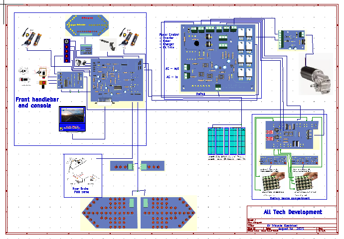 To the left is a depiction of the whole system.Moving left to right, top to bottom; we have Front console and handle bar controls, then the charge / inverter at the right side electrical compartment, and the motor drive also in this compartment. Moving down and to the left we have the brke sero for rear brakes, lights, solar array panel and finally battery pack control/BMS/and the batteries.
The system can be adjusted to work with either 24v or 48v by 1) changing the transformer from 60v (48v system) to 30v (24v system), Wire Solar in series (48v 2A) or(24v 4A), and wire the battery pack (48v=15 cells in series x 6 in parallel) or 2x (24v = 8 cells in series x 6 in parallel).
There are 7 related systems to the Tricycle:
- Front controllers
- Raspberry PI Computer
- Power Inverter
- Motor Drive
- Brake servo & lights
- Solar array
- Battery Management.
Portable Raspberry Pi Computer

The Raspberry Pi 3b is a credit card size computer. In my application, I will be adding it to a 4.3 inch display and housing it in a custom case. The computer will be used in 4 modes of operation. The first mode is stand alone mode. Under this mode it will have external power, keyboard, touchpad, Camera, Harddrive, and optionally hdmi display and breadboard features. The second mode is as an E-trike control module that can run a Solar Electric Tricycle. Mode 3 is as a CNC controller for milling and 3D printing and finally mode 4 is as a 3D scanner.

Mode 1:
Applications:
- Desktop apps Word processing, spreadsheets, presentations, Gimp, Programming
- Internet browsing, emails, online banking
- Electronic Design and breadboard testing
- RFID tag processing for event sign-in , entry, exits
Device use
- USB-c power to unit using 2A wall xfmr
- CSCM attached 4.3in touch screen display
- USB-1 keyboard / touchpad doggle to remote keybrd
- USB-2 Printer
- USB-3 2TB external hard drive
- USB-4 unused
- WIFI internet / cell phone link
- Cvid webcam
- ETH0 network
- GPIO20 Breadboard connect
- RFID tag reader
Mode 2:
 Applications:
- E-TRIKE charge, Solar, Battery, Inverter, controller
Device use
- CSCM attached 4.3in touch screen display
- GPIO20 EV-Tricycle
Mode 3:

Applications:
- CNC drill, shape, router, sander
- Octipi 3D Print
Device use
- CSCM attached 4.3in touch screen display
- GPIO20 CNC machine
Mode 4:
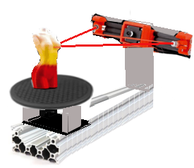 Applications:
Device use
- CSCM attached 4.3in touch screen display
- GPIO20 3Dscanner
Case construction:
The case is made from blue Plexiglas pieces cut to size and bonded together using acetate glue. Careful placement of access holes to features allow it to fit into the Etrike, CNC, and 3Dscanner frames.
 Fully assembled the unit is 4.88 x 4.95 x 1.5 inches. In the E-Trike application the top HDMI and PWR and Right side ETHO USB1-4 are hidden from access by the frame it fits into. The CNC and 3Dscanner have provisions to allow access.
Special note: The image edges closest to the top mount to the top along the black lines. In this way the vents , GPIO and CAMERA are above mounting frames and all others are obscured by the frames.
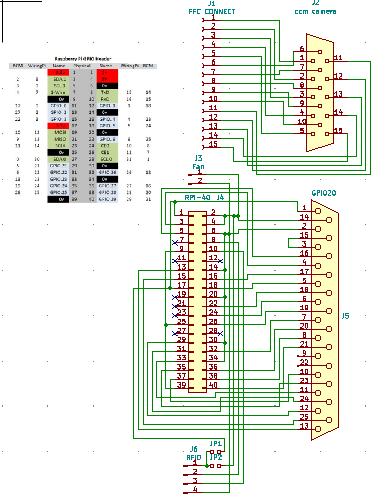
Wiring the RPI is fairly simple. A 40 pin GPIO connector connects to a breakout board. This breakout board has 2 pins to power the cooling fan, 3 wires to the RFID pcb with loop antenna and a 25 pin D socket. A 15p FFC cable comes to an ffc socket on another pcb with a 15p D socket for a ccm camera.
Everything to wire this up fits in the case as shown except the ffc breakout module. To make this module fit it has to turn verticle because the inner wall is in the way of it fitting horizontal. The perf board to interconnect the wiring also will need trimming around the fan.
To complete the portable raspberry pi 3b computer, we add a base plate with edge tabs for screwing it into place.
To the left is the wiring chart and schematic diagram for the system. At the top we need to convert the ffc-f cable into a 15pin camera connector. Below that we have the GPIO20 (GENERAL PURPOSE INPUT / OUTPUT connector) wired to a 25pin D connector and to a fan tap and
rfid connector.
Bill of materials:
- 1 Raspberry pi 3b https://www.amazon.ca
- 1 32GB microSD with noobs Raspbian preloaded https://www.amazon.ca
- 1 4.3” TFT touch screen display https://www.amazon.ca
- 1 1.3” case fan
- 1 RFID-uart board with ring antenna https://www.amazon.ca
- 1 ffc breakout board https://www.amazon.ca
- 1 DB15hd-F connector board https://www.winford.com/products/pbc15hd.php
- 1 DB25-F connector https://www.winford.com/products/pbc25.php
- 2 12” square blue plexiglas https://www.amazon.ca
- 1 bottle acetate glue https://www.amazon.ca
- 1 sheet rub on letra-set letters
Copyright 2023 ALL TECH DEVELOPMENT all rights reserved.
Portable RPI battery pack
The Raspberry Pi portable computer needs a battery pack to be really functional.

The case matches the RPI case in size and pieces only this time 3 batteries 32700 type lithium with their mounting take the place of the RPI and display. In the lower connection section we have an on-off-on switch, a power jack and the DB25 female connector.
The circuit of the lower section contains a coulomb counter, and regulated power supply.
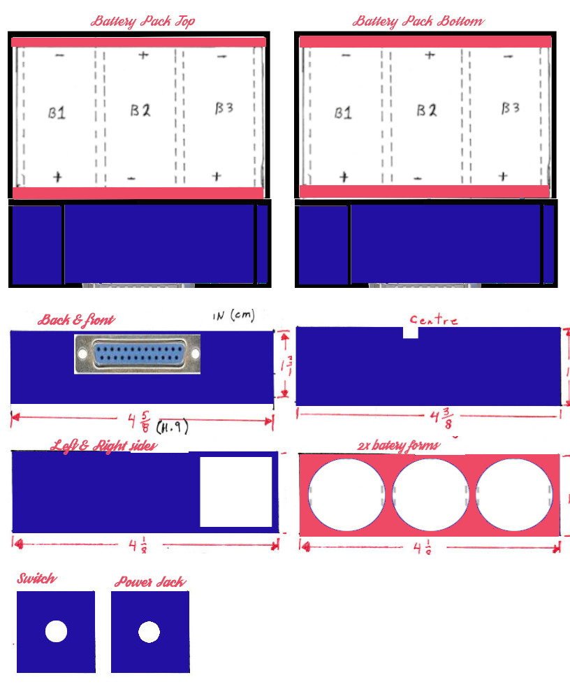 Here we have the piecing layouts to make the battery cabinet. Once we have the enclosure we have to populate it with the electronics. Below left is the circuit diagram and to the right the circuit board.


3 Lithium ion batteries provide 9.6v @ 6Amps to a 3 position toggle switch. This switch is run mode , off , charge mode. In run mode, the batteries supply power to a 5v regulator circuit which passes that power to the computer through the 25 pin Dsub connector. In charge mode a 9v ac adapter provides power to the computer and the charge circuit. In both cases the computer reads the Coulomb counter to know whether the batteries are being charged or discharged. It disables charging when the batteries are full and does a shut down when batteries are depleted. Without the battery pack connected the Raspberry Pi can be powered by the usb type c connector or by connecting the RPI with it’s Dsub connector to the tricycle, 3D scanner, CNC machine or electronic breadboard attachments.
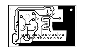


We now have a viable portable Raspberry Pi PC which is every bit as functional as a laptop PC but with capabilities that no laptop can do on it’s own.
Front control system
The front console
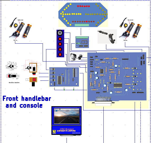 The front console collects all input signals from switches, brake levers, twist grips, and sensors. It passes these onto associated circuits which direct actions to take, lighting, signals, motor drive, braking, and charging.
The main controller is a two part system. Part A is a Raspberry Pi 3b credit card sized computer that was just detailed. Part B is the control part. When the part A is connected to part B by it’s 25 pin D-Sub connector the trike becomes operational. Part B has at the front, a signal light assembly with Left turn, Right turn, Marker lights, and even a robotic eye. The console extends in a sloped fashion towards the back. On the face of the console is an insert cavity for the Raspberry pi to fit. At the back of the console is DB25 female connector. The console mounts to the handlebar supports and the headlight mounts beneath the console. All wiring enters from below the console to prevent moisture entering the system.
On the face of the controller is left and right turn LEDs and cylon / kitt car roaming eye. On the top next to the computer is the key switch, headlight hi and lo beam switches, hazard switch, and marker light switch. From the controller going to the back we have Power, Battery monitor and Battery bank control, rear brake control, rear lights, and motor drive control. I am doing a 24v Solar Electric Tricycle with an adapted wheelerchair motor.
Front signal system
The front signal system is an LED panel shown below. The LED strings for left or right turn draw .02A during on/lit. The cylon / kitt eye also draws .02A as does the marker Lights.

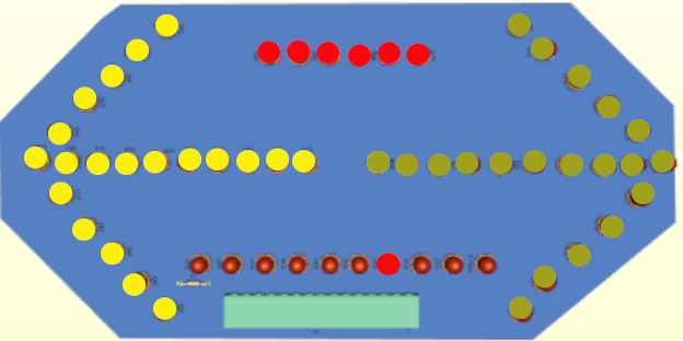
There are 3 strings of series wired led's; one for left turn one for right turn and finally the marker running leds. The cylon eye at the bottom have one side of each LED tied to a pull up resister and the other side going to connector.
The CYLON EYE
The cylon eye moving a light back and forth while the tricycle is in use is much like the nightrider kitt car. The front signal system board described earlier is powered by a cylon control board which passes the turn signal lites on or off when needed, displays the marker lights when needed and sequences 10 LED’s to turn on and off in a back and forth motion. This board mounts in the front display
behind the signal board.
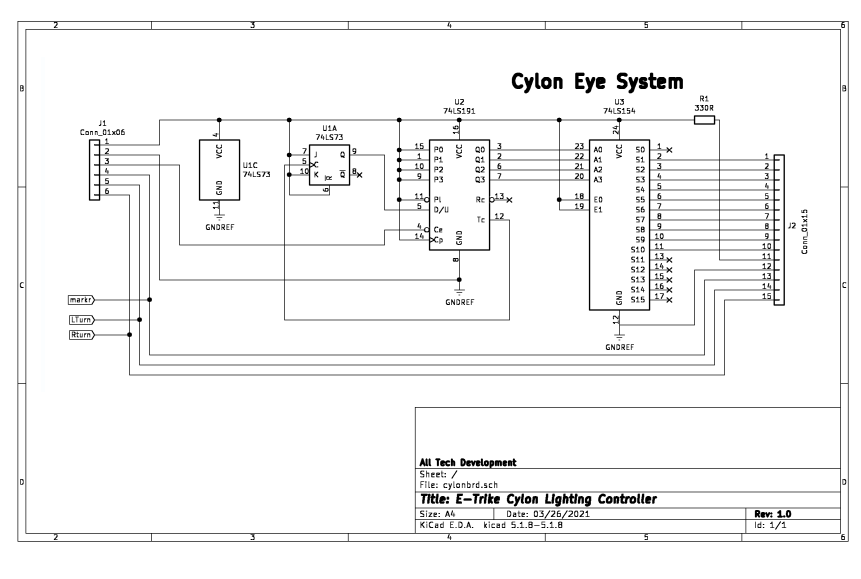

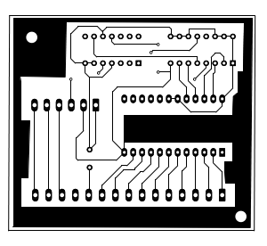
A simple 6 wires provide power, clock pulse, marker and light control. The pulse feeds a 74ls191 up down counter which in turn feeds a 1 of 16 decoder that selects which

 light to turn on. Each time the counter hits terminal count it gets it’s direction changed which cause the light sequence to move back and forth.
The board is 2.26” x 2.4”
Brake, Accelerate, speed, and signaling
These devices are used to feed info to the front control console.
 A left side accelerator acts as a brake for the rear brakes, and a right side brake lever sends signal for front brakes. Motor acceleration control is on the right side and signaling from the signal / horn control on the left.
The custom signal / horn unit is below.
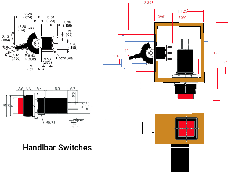

The signal light switch is positioned close to the left hand grip for easy activation of left turn, right turn, and horn.
The front controller Input and battery controller
 This board fits in the front main controller space above the main board. It uses I2C 2 wire communication and a mcp 23017 16 bit i/o expander to gather switch information from the L/R turn switches,
hazard switch, and front brake lever. It sends for L/R flash when needed, brake on when needed, samples the pol and int pulses from two Battery banks for determining charge and discharge rates and controls which bank to run the drive from and which bank to charge. When parked, It can also handle 120V AC out from an inverter and shore
charging of the batteries.
This board fits in the front main controller space above the main board. It uses I2C 2 wire communication and a mcp 23017 16 bit i/o expander to gather switch information from the L/R turn switches,
hazard switch, and front brake lever. It sends for L/R flash when needed, brake on when needed, samples the pol and int pulses from two Battery banks for determining charge and discharge rates and controls which bank to run the drive from and which bank to charge. When parked, It can also handle 120V AC out from an inverter and shore
charging of the batteries.

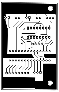


You will note I use optic couplers to prevent over loading the computer drive lines.
The controller main board
 As a means of keeping things as compact as possible the main board handles the analog stuff and the board last reviewed handles the digital stuff.
Analog switches on the front top of the unit for high and low beem headlights, horn, accelerate and decelerate twist grips come into the controller on the left. At the top we have the key switch, headlight connection, horn connection, and power from the Battery compartment. In the main body we have a multivibrator circuit for signals and cylon eye, a PWM circuit for operating rear brakes, driver circuits
for the rear lights and computer connection.


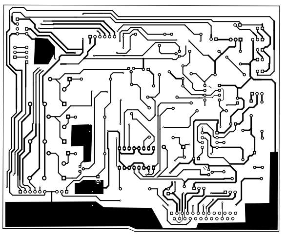

From the front controller there is a 25 pin D connector to the computer, 3 power connections to the battery banks, 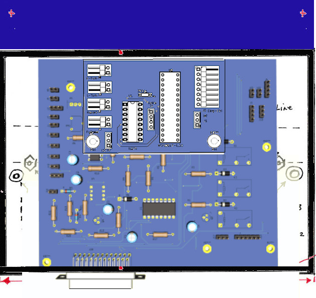 an 8 pin ribbon cable to the battery compartment for charge run control and wiring to the rear lights.
The front lights are in the blue area at the top. Also in that area is the cylon eye circuit. The two boards that make up the control circuit fit nicely in the main compartment.
Solar Electric E-trike Controller Construction
 Seen to the left we have our front console top plate. Around the edges of the hole we glue four side pieces and to the bottom we glue a base piece to form a recess box for the Raspberry Pi to fit.
Note that the back of this box must have drain holes in case water collects in the cavity.

In the above side view I show the placement of Raspberry Pi into the top form. The top form then fits onto the front, back, and sides of the console as below.

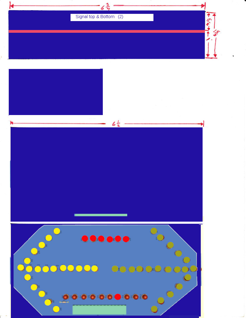
I set the top of the console aside and move onto the signal light section. The signal light section is a 1-5/8” four sided box with a central insert to make a front and rear 5/8 in cavity. The front cavity will the LED signal lights and cylon type robot eye and will be sealed in clear epoxy. The rear cavity has the lighting electronics and back mount panel. The back mount panel makes it possible to fit against the back console.
First things first. We need to align the center piece along the length of the top piece shown in pink at the left. Then we secure the two sides line up and drill out 15 holes for the display wires.
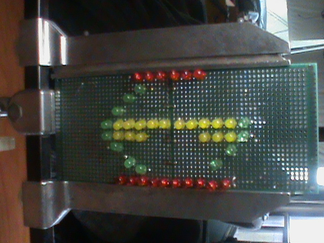
I then place the pre-wired LED display in the front cavity such that it’s wires protrude through the holes.
Making a pre-wired signal array.
So with my pre-wired LED signal assembly placed, I fill in around the wires, mix up some clear epoxy and pour over the pcb and fill the front cavity and let set and harden into a solid sealed light assembly. Next up is the control circuit that will mount to the back of the central divider. The use of connectors are optional. Ribbon cables work just as well. As a final step to this we glue two mounting strips either side at the back. I then set this section aside to concentrate on the lower console.

Shown left top is the front console piece that will mate with the tabs of the LED assembly. It mates with the console base along the top edge in black.
The console bottom has the position of the handle bar and headlight alignment indicated along with placement for 2 mounting nuts.
There are four grommets indicated for wiring to left and right handle bars and 2 for wires going to the rear of the tricycle.
The back panel is notched to facilitate the box under the top cover and is secured to the base along the line in black. The back also has the DB25 connector for connecting the Raspberry Pi 3b computer.
The last part of the case assembly is the two side panels as shown. The side panels need mounting lobes in the inside to enable securing the top panel down.
With the case now complete it is time to feed the cables into the grommets under the case. Of course this means the case will need mounting on the Tricycle handle bar.
As far as wires go we have the following :
- Left handle bar brake lever 2 wires (front brakes).
- Left mounted horn switch 2 wires
- Left mounted turn signals (Rturn,Lturn) 3 wires
- Left brake throttle 3 wires
- Right handle bar brake 2 wires (optional)
- Speed sense 3 wires
- Right Acceleration throttle 3 wires
- horn 2 wires
- Headlight 3 wires
We only need 1 brake lever for the front brake and it is paired with the brake decelerate brake throttle on the Left side, The front brake caliper is cable driven from the Left brake lever. The horn and headlight are one piece mounted to the underside of the controller.
Going to the back of the tricycle we have +24v, +9.6v, PWM brake servo 3 wires, and Gnd. Then we have Lturn, Rturn, Marker, 24v, Gnd. So 11 wires going to the back. So it is time to add the contol board to the system.
On the handlebars we have Rear brake twist grip, front brake squeeze lever, turn signal and horn switches on the left. Central is the console and at the right is accelerate twist grip. Down at the front wheel is a speed sensor. The console itself has headlight below it with horn, left right turn signals at the front face with marker lights and robotic cylon eye. On the top of the console is the key switch, headlight hi and lo switches, hazard switch, and marker switch. A removable Raspberry Pi computer also fits into the top. Three circuit boards fit inside the console. One powers the robotic cylon eye to move back and forth. Another gathers information from the switches and enables the computer to both monitor and control battery banks. The last circuit board connects to the computer and controls braking, rear lights, and battery management.
PWM Brake System
Brakes and lighting
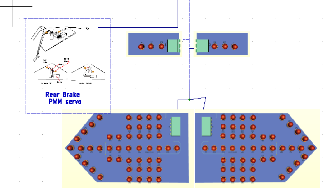 A PWM signal from the console adjusts rear brake pressure to a servo during braking. All lighting is LED and on either side of the box is a marker light. At the rear is left and right turn, brake, and marker lights.
The rear brakes operate from a PWM signal sent by the front console when the brake grip is used. Normally the handlebar grip is twisted back towards you to achieve acceleration and that is how the right one functions. The left one rotates the opposite direction or twisted
forward to achieve braking.


If we look at the two rear wheel depictions above, the one on the left sits below the frame and the one on the right sits inside the frame. The brakes salvaged from the second donor bicycle are identical which means the cables when they are mounted in the back exit both on the same side. This is bad since an in frame mount would have one cable entering the basket area but the other would exit into the storage and pass through the battery compartment. If we mount below the frame neither cable pass into the basket or storage or battery compartment.


This depiction shows an in frame mount feeding to the servo that rotates a round disc with the cable ends secured such that when the disc rotates it applies pressure to the brakes.

The servo rotates based upon the pulse width given so Ideally the handlebar grip at rest is sending position -90
half on is position 0° and full on is sending +90°.In our case -90° has 0 load and +90° has both brake pads engaged on the rim.
Solar Electric Tricycle Charge Inverter
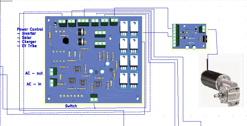
 The tricycle as designed, has a built-in shore charger, 120 V AC power inverter, solar charge panels and Motor drive control.
On the right side rear is the electronics compartment. It has covered outlets for charge cable and AC inverter output. There is a mode switch just to the left of
that. Lower on face of the compartment is the charge inverter unit. Inside the cabinet is a 5 amp circuit breaker and the motor control board & charge control board.
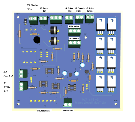


Power control
The power control center selects the mode of operation. The modes are Shore charge, Power inverter and EV-Trike. The 120vac outlet runs from shore power in shore charge mode or from battery during inverter mode. The solar panels provide 30v DC charge when deployed and the shore charge circuit can also provide 30v DC charge when in shore charge mode. Tne EV-Trike mode the motor is driven under control of the front console.
 Left side half way down is the connector for the off board transformer. Below that is shore charge in (J1) and below that is AC out (j2).
Top left we start with:
- solar charge in (j3) raw 30v DC from Solar panels
- shore charge 30v DC out (j5) shore charge power to battery charge control.
- solar charge out (J4) to Battery charge control
- (j6) Battery feeds from Battery charge control
- Console 25.6v supply(J7)
- PWM Motor Supply (J8)
- PWM power (J9)
- Console Accelerate grip (J10)
- Console 9.6v supplu
- Mode selector switch
Mode 0 : The whole Tricycle is off even if the key switch up front is
on.
Mode 1: The on board transformer and rectifier bridge supplies power to the Battery charger to provide 5A charge to a selected battery bank , it also supplies 120V AC to the AC output connection. As such the Tricycle can run a drill, saw, router, or even portable tv or even
cell phone charge in this mode.
Mode 2 : The onboard transformer and Inverter circuit is configured to draw power from the Battery banks to provide 120V AC out. As such the Tricycle can run a drill, saw, router, or even portable tv or even cell phone charge in this mode when no shore line is available.
Mode 3 : Enables the Tricycle to operate as a mode of transportation. The Computer and front circuit controls all operations.
The function switch determines the mode by placing 9.6v onto 3 of 4 switch positions. The first position is off (no connection). The second position powers an optic-triac to drive power triac which enables the ac in line to feed the external AC out receptacle and the primary of a 120v to 30v AC transformer which in turn passes the 30v to the output rectifier. The rectifier then powers the charge circuit in the battery compartment.
The third position powers two optic-triacs to drive two power triacs that reverse the transformer to power the AC output as the destination. The source of this transformer is an inverter driven by a 60 hz full wave saw tooth oscillation. The DC 9.6v becomes 19.2v AC multiplied
by 5 = 96v AC which is sufficient for cell phone charge, some simple power tools but not recommended for Powering digital electronics like a PC or tablet except to recharge them.
The final position provides the 9.6v Battery power to the front controller. There the circuit takes the 9.6v to a key switch which then sends the voltage to the computer interlock. If the key switch is off, or the computer is not attached nothing gets power. With key switch on and computer attached, a 5v regulator is powered which powers the computer and upon initialization of the tricycle program the trike comes to life.
The Solar input is simply current limited and fed to the Solar output with blocking diodes so the batteries can’t back feed into the solar cell array when there is lack of sunlight. The 25.6v battery run output feeds both the charge converter here and the front controller, and drive controller. The accelerator hand grip comes into this board and is passed to the drive controller. In the Battery compartment the circuit takes information from the computer to determine which battery pack gets charged and which battery bank does the motor running.
EV Tricycle Drive System
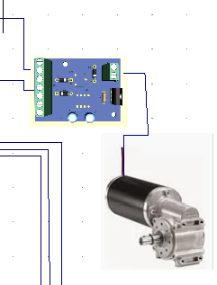 The wiring is straight forward. The motor connects to the 2 terminal connection. If the motor turns the wrong way reverse the wires.
The 7 terminal connections are:
- 24v DC
- 5v DC
- (+) handgrip
- (sense) handgrip
- (-) handgrip
- GND
- Brake (0 = on 5v = off)
Motor is disabled when brake is on.
The Tricycle uses a salvaged wheelchair Motor as it’s means of movement. This type of motor is a DC motor with an Electric permanent magnet brake. The brake actually draws a fair bit of power to disengage it to move. In our application, the brake simply stops movement of the drive gear but allows the freewheel gears and axle to still function so it really does nothing. In the original purpose, two motors propel a wheelchair with 300 lb occupant up to 8mph for 10 hours from two 12v @ 25A batteries in series. A full 1A per hour is used to disable the brake and 1.5A per hour to move. So step 1 is to remove the magnetic brake from the motor. This is a very strong real earth magnet that can easily do real damage to fingers. As powerful as it is, with effort you can still push the wheelchair with the brake on. We loosen the rear screws and slide a piece of plastic between the magnet and the metal friction plate. Once fully blocked from mating we can finish unscrewing the back and remove it. Take the
magnet out of the backing and safely store or dispose of it. Re-install the backing.
The Motor now needs a mounting bracket on the Tricycle with at least 8 inches below the basket. The original design had the motor attached to a 10” wheel and will now be attached to a 7 inch sprocket with a chain to a 3 inch freewheel. The 10 inch wheel travels 31.465 inches (2.62 ft) per rotation. At 8 mph it makes 16,110 rotations per hour. By changing to a 7 inch sprocket we have changed the distance to 1.835 ft per rotation but not changed the maximum rotations per hour. The 7 inch sprocket drives a 3 inch freewheel gear 2.33 times faster so this does alter the rotations per hour to 37,588. The freewheel gear rotates an axle and a 3” drive sprocket connects by chain to a sprocket at one rear wheel. The wheel is 24 inch traveling 37,588 rotation per hour. The 24 inch rear wheel travels 75.516 inches per revolution (6.29 ft) so at 37588 rotations per hour the maximum speed is 44.8 mph (72.66 kph). To be both safe and legal we must not allow speed higher than 30mph (50 kph). With 37,588 rph we get 626.47 rpm (rounds per minute) or 10.44 rps. We need to trim the maximum 37588 back to 25865 or 431rpm or 7.18 rps. This can be done by adjusting the input reading of the accelerator hand grip.
 The wheelchair uses a controller with both forward and reverse H-bridge drives to two two independent motors which provide for 360 degree rotation and full range forward and back movement. We only need forward movement since the tricycle drive design doesn’t allow backwared motion and the handlebars govern left to right or forward motion. As such we only need a simple PWM control as below.


The Motor is driven from the 24v main line. The PWM circuit is driven from the 5v line. The next 3 connections are the (+), (sense), and (-) of the handgrip accelerator. We then have ground and reset (brake applied).
The Solar EV Tricycle Array
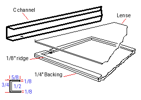 Above The wheelwells on either side of the Tricycle are two 9.5” fold out solar panels. Each panel set provides 30v @ 1A to 2A if sunlight is sufficient. Each panel consists of 0.25” x 35.75” x 9.25” plywood backing with a 0.125” x 0.5” edge trim and a 0.125” lens.
A 0.625 x 0.75 u-channel encloses the edges to seal the panels. The u-channel is chrome or polished alluminum trim and the two panels on each side are connected by piano hinge such that when not in use they cover each other with the lens facing each other.
Surface area for the solar cells is 34.75” x 8.25” due to the chrome boarder. The cell width for 2 columns per panel is 8.195”. We have one column of 16 cells and one of 14 cells which means we need 32” for 16 cells plus 2.125” of separation between cells = 34.125” total length. One panel on each side mounts over the wheel well with the hinged panel folding over the basket area. All cells in each panel are wired in series with panel one row 1 (+) top left (-) bottom left with 16 cells, row 2 is (+) bottom right (-) top right with 14 cells. The adjoining panel has 14 cells in the first row with (+) top left and connects to the first panel row 2 top right. Once more (-) bottom left connects to row 2 bottom right (+) and (-) top right passes back into panel 1. (+) row 1 panel one goes to the electronics bay solar in. (-) row 2 panel 2 goes to the electronics bay (-) or ground. The panels on the other side are wired the same but this time panel 4 mounts above the wheel well and the wires pass into the electronics bay from panel 4. (-) panel 4 row 2 goes to ground and (+) from panel 3 row 1 comes into panel 4 and connect to (+) solar in of the electronics bay.

Cells are 4” wide by 2” high
30v = 60 cells in series 1A
2 sides in parallel = 30v 2A the cells deliver between 1A and 2A and I have gone with the lower figure with my calculations
Panels themselves, are made of either monocrystaline or polycrystaline cells. monocrystaline do so in a much smaller panel than the polycrystaline ones and are more expensive. The Panels themselves are fairly thin but mounted to a heavier structure or frame to give it strength in adverse weather. For optimum efficientcy you need to keep the panels clean from dirt and debris. Before moving on lets talk a bit about cost comparison. A monocrystaline cell can typically cost about $3.60ea. Comparing to polycrystaline the cost per cell is $0.13ea.
Now lets make it happen
- Step 1: We can make 4 box frames 9.5" x 36" using 3/4" U-channel.
- Step 2: 1/4" plywood back plate(s) cut to fit.
- Step 3: On the plywood surfaces we need to mark out 2.125 x 4.125 squares into rows and columns observing there must be a 0.5" border around the edges and room at either end for wiring bussbars.
- Step 4: Glue a 1/8" thick x 1/2" edge strip to go all the way around the plywood outer edges.
- Step 5: Cut a 1/8" UV plexiglass lens to fit
Custom solar Panels
Basically you have UV protected Plexiglass about 1/8th" thick covering a 1.3mm thick fragile solar cell and backed by a rigid backing that may be 1/8th to 1/2" thick sealed in an environment tight frame.
Dirt, grime, and moisture are the main culprets to the demise of panels from an environment standpoint. This is especially true when making the panels. From the in use perspective, you want a strong construction that is light in weight and not prone to bending. You must never let anything especially fingers touch the surface of the cells. USE NON-COATED INSPECTION GLOVES when handling these cells. They are fragile and easy to break. A well made panel has a life expectancy of 15 years. So lets look at what you need.
- 1/8th" Thick UV Plexiglass 36" x 36"
- 4'x4' x 1/4" Plywood
- Silicon clear caulking
- (120) 4" x 2" polycrystaline Solar cells
- 1 spool tapping wire
- 1 spool bussing wire
- 1 spools Red 20ga wire
- 1 spools Blk 20ga wire
- (4) 3/4" x 1/2" 'U' channel 8'
And for tools:
- Lexan cutter
- 3 ft ruler
- speed square
- Drill & bits
- Flux pen or solder paste
- 60/40 solder
- wire stripper / cutters
- 60 watt soldering iron
- Marker pen
- Multimeter
Down to Business
We are going with a sealed aluminum frame design.
Before we get started assembling cells lets actually do the frames as previously described. You can secure the 1/8th inch plexi to the plywood and fasten the plywood to 3 of the frame edges from the underside. Seal the mitred edges with rubber cement. Using the lexan tool you can score the Plexiglass and make a clean break.
 First Dry fit: With our backings all ready we should be able to place the Clear plexiglass into the frame and fit the 'U' channel over them for a very tight fit.
Two of our custom array will mount over the wheel wells. 14:2 electrical wire will pass from our panel through into the compartments below
Wiring path
We are going to have 4 panels with 16 cells on each column and 2 columns per panel with 2 unused cell spots per panel.

Here is the diagram of a 5 bank system. Ours will be a 2 bank system. This solar controller then feeds onto a main buss. which connects the charger and Battery bank. The main power feed comes from the contactor to the computer and motor inverter and drive systems.
Wiring up the cell Banks
It's about time we get to making the actual solar array. We have 120 cells to configure into 8 columns of 16 cells. Gloves on!, make sure your area is clean and open the package of 200 cells. Grab your multimeter, A piece of copper PCB and some wood to make a little stand. We will want to take a piece of plywood about 5" square and place a small 1"x2" by 5" along one edge and
2"x2"x5" piece of wood along the other edge of the wood square. Then place a copper shiny side up angled between the two pieces of wood block. As we check the cells we will lay the dull side against the copper such that the positive cell contacts the copper. In this way we can check the voltage and amps of each cell easily.
The cells will have 6 positive contacts on the dull side and two negative strips down the blueish face. If you bought tabbed cells each cell will have tap wire soldered to the facing. If you bought plain cells you will need to solder tap wire to the facing. But for now, just place the cells one at a time face up on your jig and measure with positive on the copper and negative on the face strips looking for .48v and again for 1 to 2 amps depending on sunlight.
Tap stripping the cells.
For each cell pair we need the tap wire to cover the negative strips on the face and connect to the underside positive contacts. The tab wire does not need to pass past the end of the next cell. So 2" is all you need given that each must be spaced 1/8" apart. If you bought tabbed solar panels you only need to trim the tab wires to 2".
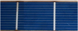
After you have got your work area setup, and tab wires cut to about 4.125" You are ready to start soldering. The soldering iron I use is adjustable from 10-100 watts, I have it set for 40 watts. Be sure that your iron tip is clean and tinned properly, as you work keep cleaning the tip because a dirty tip will possibly contaminate the process.
You see in the picture there are white stripes from top to bottom. These are where you will attach your tabbing wires. The tab wire is not completely at the top of the solar cell. This is just to be sure it does not contact the cell that will be above it.
- First you need to use the flux pen. put a light coating of flux on that white stripe. You see the darker blue areas, that is flux that flowed off the white stripe.
- Lay your tab wire on this stripe.
- Using a soldering point tool (or something similar) to hold the tab wire in place. don't press to hard, you might crack the solar cell under the tab wire.
- Moving from top to bottom, use your soldering iron and start soldering the tab wire down. Don't let your iron set in one place to long, you will burn the solar cell. You will need to move your holding tool around as you move the iron down, don't let the tab wire move. Hold the tab wire down until the solder cools.
- Repeat for all tab wires on each cell.
Cell inter-connections

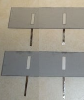
As you have enough cells tabbed to do 2 rows (30 cells) we need to interconnect them one row at a time. Remember the blue face is negative and the back is positive. The back may have either 3 contact spots in two rows or 2 partial strips.
- Flip over all the cells that need to be connected, and put flux on the white areas.
- Lay the tab wires from the top cell onto the back of the bottom cell. All cells need to connected front of one cell, to the back of the next. This puts them in
series. And keep the cells 1/8th inch apart and tab wires must not extend past or even close to the ending edge.
- Solder the connections.
- Repeat until you have all 16 connected.
These cells need to be connected in series because each cell produces 1/2 a volt DC. We are making a 15v panel so we need tie them in series. This is a "no load" reading. When these cells are put under a load, such as charging a battery, the voltage should drop a bit. When all 2 series string are connected, we should see 15 volts.
Connecting cell Rows
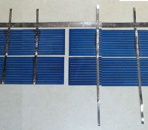
We are making 1 panel with 30 cells in series. Now I will show how to connect 2 strings together.
As I stated before, cells need to be connected front side to back side. On the end of the string you need the 2mm tab wires protruding from the ends of the 2 strings you need to join. You can use shorter tab wires for this if you want to.
- Add tab wires as needed to the end of the strings.
- Lay the strings next to each other with a small space in between them. I would recommend doing this on the glass you will be using for the solar panel, or on something that these cells can be kept on until they are ready to be put into a panel.
- Measure out the length you need for the buss wire. Then cut the 5mm buss wire to your measurement.
- Use the flux pen on the places that the buss will be attached. You only need to put flux on the tab wires, not both tab and buss wires.
- Line up your buss wire on one end of the tab wires. The buss wire does not need to stick out over the end, just make it even. Keep it close to the cells, but do not touch them.
- Work your way from the first one you soldered, keep the buss wire flat as you move.
- After you finish soldering, cut off any of the wire sticking out past the ends of the tab wires and the buss wire.
In the picture where the extra wire has been trimmed off you see an extra tab wire on the left string. I put that tab wire on there to test the cells to be sure they were connected. I stated earlier that cells produce 1/2 a volt, so 4 cells should be 2 volts. I was sitting under a incadescent light when I tested these cells. I got a reading of 1.4 volts. That is very good since most cells will not work unless they are exposed to real sunlight.
Remember when testing and connecting the wires that will run out of the panel the top side of the cell is negative, and the bottom is positive.
End of strings
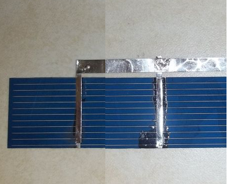 In addition to connecting strings you will also need to put a buss wire on each end of your cells (cell 1, and 39). This is done in the same way as connecting 2 strings, but you are only connecting the 2 tab wires on that one end cell (1). But on other end you are connecting all 4 wires to the buss wire. I leave a little extra hanging over on the ones on the top. I do this so that when I add a copper wire that will run out of the panel I can fold the buss wire over the copper wire and solder it together, making a stronger joint.
The buss wire can be done before or after connecting strings, that is up to you.
Panel assembly
With luck you have two strings made in series with 1/8" spacing between each cell and each row. At one end you have two buss bars (+) & (-) and at the other you have one long buss bar connected 2 tabs of column 1 to 2 tabs of column 2. So now take your template and transfer the markings for the bottom to the plywood (frame is taken apart for this). I would put a center hole through the template for each of the cells and then mark the back plate where we need to put a drop of silcon sealant. Remove the template and apply the sealant. Now carefully position panels observing that you place them the right direction with the double buss bar at the top. You might want to also put sealant under the bottom buss bar. DO NOT PRESS TOO HARD on the panels or they will break.
Apply silicon sealant to the U channel (one with the wiring holes) and place the frame piece into position. Use a 1/8th piece to simulate the lens for now. Feed a Red wire through one of the holes and extend it across to the left buss bar at the top. Strip and solder the Red wire to the buss bar. Next Feed a Black wire to the other buss bar and strip and solder it. Where the Red wire goes all the way to the other side of panel array, this black wire needs enough length to feed into the next panel and to the top left set of rows. About 25 inches should be plenty. Cut and feed another black wire into the panel and back out. this wire will also go to the other side. Apply silicon sealant to the hole inside and out to seal it from moisture. Use a piece of tape to mark the wire that goes to the other side.
With this done you can now assemble the top and bottom parts of the frame using silicon and the 1/8th" spacers. Remember to also put silicon sealant on the ends of the frame too. Flip the frame over and using a small pilot hole drill 1/2" mounting holes around the frame and put in 1/2" #6 roberts screws to secure the frame pieces. Lastly slide the lens (with protective cover removed) into the frame from the open edge. Silicon and install the final U channel and drill and screw it from below. Now seal around the Plexiglass where it meats the frame. 1 Panel Done!
EV – Tricycle Battery Management system
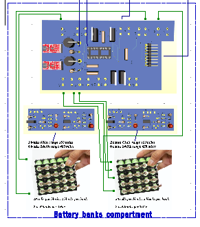
The Solar Electric tricycle battery management system consists of two 36A x 24V lithium Ion battery banks which are switchable. While one bank is operating the drive system, the other can be solar charging under computer control. Each bank has it’s own bms and switchover controller. The banks themselves have 6 parallel batteries making 36 A and 8 series batteries making 25.6V out of the 48 cells per bank. Cells are 32700 series lithium ion phosphate at 3.2v @ 6A. During run operations we have 25.6v @ 36A and During charge we have 30v @ 2A to 4A during solar charge operations and 30v @ 10A if shore charging.
There is an important consideration here. We must look at run, charge, Kilowatts and load for the intended application of the pack. They all inter-relate. Load: = Curb weight + Payload + road conditions. Kilowatts = voltage x Amps / 1000, Distance or range = KW/(Load/10000). Run is the drain on the battery bank. Charge is the recovery of the battery bank.
We know curb weight is 171 lbs consisting of frame 75 lbs, motor and axles 21 lbs, batteries 36.72 lbs, solar panels 29 lbs, and electronics 10 lbs. We know the Kw = 25.6 x 72A = 1843.2 /1000 = 1.843. None of these will change so our maximum limit of travel is kw/(load_1/10000) = 1.843/(0.0171) = 107 miles (179 Km). But and there is always a but, we can't fully drain the batteries so the real range is 4/5's of 107miles = 85 miles (142.6km's). This is without rider and cargo or road conditions.
Using myself as the rider the change modifies the range to 1.843/(0.0363) = 50.74 mile (84.5 km) and real range 67.65 km. I can pedal assist on hills to reduce ill effects. Because my axle is a freewheel axle to allow pedal assist there is no regenerative braking. Fully loaded 563 lbs further cuts range to 1.843/(0.0543) = 32.74 miles (54.6km) and real range of 26.19 miles (43.65km). A note here is due. When auto makers state range it is from curb weight without passengers or load. They can get away with this on ICE (gas and diesel) vehicles because most people see the high range and don't calculate the real figures.
So what about charging. From shore charge, we get 30v @ 10A = 0.3KW maximum and can fully recharge with-in 4.91 hours. Solar charging functions on the unused bank 30V @ 4A = 0.12KW and can fully recharge 1 bank in 7.7 hours. This means you can ride to work (25 miles) on one bank, let it recharge while you work and in 8 hours leave with two fully charged banks.
During a charge cycle, we have 30V applied to a bank of 8 series cells so each cell gets 30/8 = 3.75V (4.2v is maximum so we are good). we are applying 4A in solar amongst 6 cells in parallel so each cell gets 0.25A (6A maximum so we are good). On shore charge we are also charging at 3.75v per cell and this time 1.66A. At present the onboard charger accepts 120V AC with a 5A draw from the 15A source. With a better charge circuit we could attain 30A at 30v for a full charge time of 2 hours and under that kind of power charge at 4.6A per cell which is still good since our cells can take a charge of 6A.
 To the left is a 12.8v pack at 30Ah. We will use 4 of these but instead of 5 cells in parallel we will use 6 cells. 2 x 12v blocks wired in seties will make our 25.6v bank and the other bank will also be 2 x 12.8v blocks making the 2nd 25.6v bank. Together they provide 50 miles (84.5 KM) of travel but then would require 5 hours recharge from shore power or 14 hours (2 days) solar recharge.
In our scenario of going Rockyford to Strathmore we use 1/2 our power getting there in 0.8 hours and it will take 7.5 hours to recharge bank 1 while we shop for 2.5 hours using bank 2. Bank 1 isn't fully recharged and bank 2 has seen maybe 0.2 hours use. We stay on bank 2 & recharge bank 1 on the run home. On a bright sunny day we return home with only 2.5 hours needed to recharge bank 2. On an overcast or dark day we use all power. When we get home we plug in and charge both banks in 5 hours. Travel for free accomplished.
Using 4 blocks of 6x4 cells we get two banks of 36Ah each. The EV-Tricycle has available space for 80 cells above each wheel well. In effect we can have 1 bank 8 cells in series by 10 cells in parallel or 25.6v @ 60Ah above each wheel well so total capacity is 192A. So theoretical range is now 133.33 miles (222 km). We are adding 52 lbs so load becomes 415 without payload. kw = 4.838 kw/mile = 0.0415 so true range = 4.838/0.0415 = 116 miles (194 km). Charge times are 3 times longer.
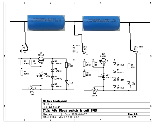
 While the schematic just to the left isn’t quite correct, it does show 10 cells in parallel by 2 series strings but that yields 6.4V @ 60Ah.
Charge vs Drain
The battery system has two systems in place. The first is a BMS that safe guards cells from over charging and the second is a coulomb counter that reads charge in and out of the battery bank. To the far left is a BMS balancing circuit that monitors 2 cells and balances them. We will have 4 of these per bank. With the adjustment you set at what threshold to stop charging. When a series cell reaches it threshold (3.75v) it quits charging that group of parallel cells.


The second system involves the computer and two coulombs counters. At 3.75v we are at 90% of the 4.2v maximum charge so the BMS will prevent the over charge. The power control board above connects to the computer up front, both battery banks, shore charger, and solar charge. With it the computer can manage which battery bank to run from, which battery bank to charge, turning on the shore charge or the solar charge and monitor each battery bank. The coulomb counters (in red) tell the computer when 0.0001707A is used or replaced in each battery bank. It does this by sending ticks plus direction info to the computer. For our 36A banks, the maximum ticks full = 36/0.0001707 = 210,896 ticks. At 20% we can't run any further on the bank so the computer knows at 42,179 ticks to warn you to change banks. When you select change banks the computer does so and waits for you to ok solar charge. When you park the tricycle you have the option to solar charge both banks and sutdown when complete, shore charge and shutdown when complete, or just shut down the tricycle.
For coulomb counting to work we need to sample up to 8.5V @ 1A maximum and here-in lies the problem our drain voltage is 25.6V @ 2.5A nominal and our charge is 30V @ 2 to 4 A. Using an artificial ground 5V below the charge discharge voltage the coulomb counter is happy since it always has 5v and has no idea it is operating from a 25.6v or 30v supply. Using an external shunt resistor and measuring 50mv across it when 5A passes through it we can compensate for the 1A maximum such that 50mv/1000mA = .05 milohms and 50mv/5000mA = .01 milohms. The computer gets 1 tick every .1707 A on the original and now gets 1 tick every .0353A
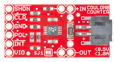 /shdn connects to VIO which is either +25.6 discharge or +30v charge
/clr connects to /int and sends pulses to the computer every .0353 A pol is low for discharge and high for charge
A 5v zener goes between VIO and GND and a 470 ohm resister goes between the GND of the coulomb counter and the real GND of the system. An ILQ2 (quad optic isolater ) safely level shifts the signals from 0 – 30v to 0-3v for the computer.
 This simple circuit board handles 2 Banks of Batteries for both charge and discharge. Connections are pol 1, pol 2, int1, int 2, GND, and 3.2V on the computer side.
Another computer circuit has drive En 1 , drive En 2, Chrg En 1, and Chrge En 2. Such that complete control is handled on 8 wires.
We could use 4 SPST relays rated for 10A contacts or use IRF540 ‘s run from ilq2 chip to accomplish simple switching.
The Mosfet can drive 19A at over 90v so it can handle our control requirements.
We could also do both charge monitoring and battery control with just 1 mcp23017 chip and use only 2
Wires. It does so using a I2C interface of 2 wires to control up to 16 inputs or outputs or any combination there of.
As seen at the left, a simple control board placed at the front controller provides sampling of the
- left turn
- right turn
- hazard
- front brake switch
- rear brake sample , and sends
- Left-Turn
- Right-Turn
- Brake states
to the front control circuits. It also reads pol and int states from/to battery packs, and issues the charge and drive control for two battery packs. Int-A, Int-B, Scl, Sda, GND, and plus 5v does all the communication with the front control board.
Down at the Battery Banks
We have 8 control wires that come from the front controller, plus a common ground. Battery bank 2 cell row 1 provides us with 3.2v for LTC4150 coulomb boards ( 0.5” x 1.25”) and the 10 resistors and 2 zeners take care of the biasing for checking charge / discharge. 4 IRF540n Mosfets connect the 2 Battery Banks for driving the tricycle or connecting the solar charge and or inverter charger to the battery banks.
T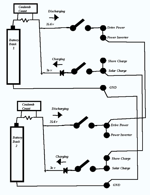 he concept is shown at the left. The Mosfets will replace the switches such that the computer can control which bank gets charged and which bank gets discharged. The coulomb counters monitor each bank separately.
When the computer is in drive mode the select drive bank provides motor power. When in Inverter mode the computer allows the selected bank to generate 120v ac from the batteries.
When in Shore charge mode charging comes from the battery charger. And when in Solar charge mode charging is from solar power.
At this point let us address the switching and monitoring circuit. In the back battery compartment we have the switchover board.
W
e have two board views. On the left is the back side of the PCB with the front topside view beside it. Below is the actual layouts.
The board has two micro coulomb modules shown red that track the charge to and from the battery banks. Along the top edge we wire +25.6v to bank 1 battery pack, next is solar and shore inputs, then we have drive and Inverter outputs, next to that are 3 Ground tags and finally +24v for front console light system. An 8 pin header goes up to the front console. Working left to right along the bottom edge we have +25.6v to bank 2 battery Pack, then we have 9.6v tap on bank 2 which goes to the front console for main power. Then we have 3.2v tap on bank 2 , next is solar and shore inputs, next is drive and inverter outputs. So battery bank 1 has +25.6v and ground. Battery bank 2 has +25.6v, +9.6v, +3.2v, and ground. The two solar inputs connect together and go to the solar panels. The two shore inputs connect together and go to the shore charge circuit. The two drive outputs connect together and go to the drive circuit. The two Inverter outputs go to the Inverter. The computer up front gets +24v, +9.6v, 8 pin cable, and ground.
So why do I only do taps on bank 2? Well the computer needs to draw power for lites, horn, signals, and itself and if it sends command to turn off the supply it is running from everything stops including itself. So I use the 3.2v, 9.6v taps for the computer and run those from bank 2 only. The computer including all lights, horn, signals, brakes use less than 2A per hour. So on a .8 hr trip, bank1 depletes by 10A, bank 2 depletes by 2A. If there is no sun and we shop for 2 hrs bank 1 may deplete 1A between stops and bank 2 depletes 0.2A. On the return trip we further deplete bank 1 another 10A and bank 2 another 2A. Back at home bank 1 has 9A left and bank 2 has 25.8A. We can use shore power to recharge both banks at 4A and be ready to go again in 6 hrs.
On the left side of the schematic we have two ltc4150 coulomb counters connected directly to their independent battery banks. An ilq2 quad optic-coupler with it’s associated biasing resisters convert 30v levels to 3v levels for the computer. At the right is the computer connection which has the top 4 lines to do charge/discharge reading , and the bottom 4 lines enabling run/charge on two banks.
The states are:
0 0 0 0 … all off
1 0 0 0 …. bank 1 run
0 1 0 0 …. bank 1 charge
0 0 1 0 …. bank 2 run
0 0 0 1 … bank 2 charge
1 0 0 1 …. bank 1 run bank 2 charge
1 0 1 0 …. bank 1 & 2 run
0 1 0 1 …. bank 1 & 2 charge
The BMS
There are 8 cell rows in series per bank and each row contains 6 parallel cells. So for each bank we build two blocks of 4 rows x 6 columns (24 cells). From the bank 2 perspective here is how it wires. Items in bold only pertain to bank 2.
- Cell row 1 (-) is the ground and it goes to BMS board 1A, and the switcher board GND and also to front controller and rear charge inverter and motor drive.
- Cell row 1 (+) goes to cell row 2 (-) , switcher board +3.2v, BMS board 1B.
- Cell row 2 (+) goes to cell row 3 (-), BMS 1C and BMS 2A.
- Cell row 3 (+) goes to cell row 4 (-), +9.6v, BMS 2B.
- Cell row 4 (+) goes to cell row 5 (-) on second block, BMS 2C and BMS 3A.
- Cell row 5 (+) goes to cell row 6 (-), BMS 3B.
- Cell row 6 (+) goes to cell row 7(-), BMS 3C and BMS 4A,
- Cell row 7 (+) goes to cell row 8 (-), BMS 4B,
- Cell row 8 (+) goes to +24v of the switcher board, +24v of Inverter, +24v of Drive control, BMS 4C
The other bank wires the same as the first bank replacing BMS #A,B,C with designations 5 through 8.


Basically the BMS boards each handle 2 rows. Batteries are 1.26” x 2.78” so each row is 1.39” wide x 3.03” high x 7.55” long. Due to storage in the battery compartment the boards have be mounted on the 3.03” x 7.55” surface of block 1, 2, 3, and 4. We also need to mount a 2.39” x 4.53” switcher board too.
S0 2 banks have 8 BMS boards 1.08” x 3.17” and one switcher board 2.39” x 4.53”. BMS is using 2.16” x 12.67” and the total space used = 4.55” x 12.67” out of the 7.55” x 12.67” Packs surface.
How the circuit works is you set the charge cut off for the cell on the associated trimer. During charge, the cell is charged until cutoff. At cutoff the led lights and the no further charging is done on the cell. Eventually all cells are fully charged and all leds are lit.
Chapter 10 EV Battery Bank system
Choice of cell types
Batteries lie as the source of energy to power the EV. The type and configuration of the Batteries determine the potential of project design. Below are the specs for the four common lithium cell types. While all four can be combined to make the Banks or packs, the cell size and availability are the determining factors to project success.
In this chapter the term cell or battery refers to the individual cells like items 1,2 and 4. Gcells will refer to the 3rd type as a Gcell that is really a group of type 1,2, or 4 arranged into a single larger device. A Bank is a group of Gcells and a Pack is a group of Banks.
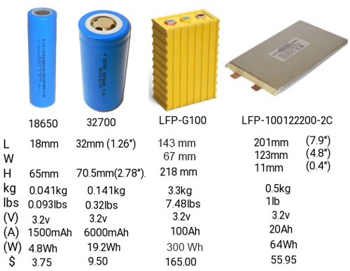
The 18650 was the original cell of choice for EV at 18mm x 65mm providing 800 to 1500mah. $5 to $12
The 21750 is the new choice at 21mm x 75mm with 5000mah $16
The 32750 is my preference 32mm x 75mm at 6000mah. $10 is the cheapest cost of the 3 and although it is bigger and heavier, when your talking about 1000’s of cells to make a pack it is significant.
Consider this:
To make a 24v 36A bank with 2 banks to a pack we need 8 rows in series by 36/cell Amps in parallel per bank with banks then placed in parallel.
- 18650 cells = 2 x (8 x 36) = 288 cells $3,456 17.28 lbs
- 21750 cells = 2 x (8 x 7) = 112 cells $1,792 10.08 lbs
- 32750 cells = 2 x (8 x 6) = 96 cells $960 30.72 lbs
Factors to consider in make an EV-Tricycle is really weight vs cost vs range in miles. We have 28" x 4" x 5" above each wheel well and an 8" x 8" x 14" battery compartment that can be used. 2 Banks of 24v can fit in the battery compartment if not using 18650 cells. If using 18650 cells it would take all three spaces to fit them all in.
Curb weight is not really much of an issue since the structure including tires can handle 1400 lbs and our weight of Tricycle, and payload (rider and cargo) might be as much as 600 lbs plus 30 lbs of battery. Miles of travel is = Kw/(GVWR/10,000) with Kw = V x A so with 24v x 72A = 1.728Kw. Total distance in miles = 1.728/0.073 = 27 miles between charges. The average person travels under 12,000 miles a year according to the insurance bureau of Canada. That is 32.8 miles per day so you could travel for each day and use pedalling, solar charge, and shore charge to fit the need. So for daily commuters the Tricycle can work pending amount of sunlight and for how long it shines.
People needing higher ranges could make use of the wheelwell space for additional batteries. Each wheelwell can hold 80 cells (8s10p) so we can get 24v x 60A at each wheelwell plus 2 x 24v x 30A in the battery compartment. This can provide 2 banks 24v @ 90A for a pack at 24v @ 180A. Range would now be 4.32KW / 0.078 = 55 miles. And this presumes you always travel with full cargo area. If you are traveling empty, your range would be 43 miles on the battery compartment pack plus 65 miles on wheelwell packs = 108 miles.
Battery Pack health
Cells decline and fail at different rates. As cells in use go through life they start taking less charge as they age. In a ‘one pack does all this can mean that if rate of decline results in say 10% of original distance the answer is to replace the whole pack for $960 for example. But because we are using Banks, If only 1 bank has declined rapidly, we can replace the bank $480. With standardization we can have stores stock our 24v Lithium Gcells on the shelves for $480 each.
Just like with lead acid where we turn in the battery for core charge so it can be rebuilt, the gcells can be rebuilt.
The whole industry is in for a shake-up if all vehicles have to be electric by 2040. 448 million vehicles in north America will have a value of 0 in 2040 unless they are electric. The EV-Tricycle may be a stop gap measure to help some people save for an EV car while providing a means to still stay mobile. While I am doing this from DIY standpoint I have to go with consumer costs of $16 per 21700 cells but OEM shops making EV-trikes could buy cells in bulk as can battery Gcell makers and source cells at about $4 per 21700 cell to ultimately reduce costs, and weight, and bank sizes.
- 21700 at DIY consumer price $16 ea, $896 per Gcell 5.04 lbs $1,792 per pack total wt 10.08 lbs
- 21700 at wholesale price $4 ea, $224 per Gcell %.04 lbs $448 per pack total pack wt 10.08 lbs
- 32700 at DIY consumer price $10 ea., $480 per Gcell 15.36 lbs $960 per pack total wt 30.72 lbs
- 32700 at wholesale price $2.50 ea. $120 per Gcell 15.36 lbs $240 per pack total wt 30.72 lbs.
The safest Packs are those with:
- Plastic or fiberglass structure so
that people can be kept away from extreme energy supply..
- No Exposed High voltage or high current connections
Gcells would have 3 screw terminals [+48v.+12v, Neg) So not that much different than a lead acid with 2
terminals (+12v, Neg). The Gcell is 30Ah and the lead-acid is 65 to 85Ah.
For very practical reasons, each bank needs temperature monitoring and control, Voltage Balancing, Charge balancing, State of Charge, State of health, and functional control. BMS is the go to method of protecting the battery banks. It isn't as straight forward as they lead you to believe. Yes the BMS protects the Battery from over voltage, over current, over temp during charging and shuts the whole process down if it encounters any such condition. It can jump in if there is a short circuit so as not to damage the battery. Under live operation, BMS is both good and bad. It tries to balance all batteries to be at the same voltage either passively or actively. But voltage does not have much to do with it compared to SOC, SOH When one cell reaches full charge BMS stops charging all cells it is in control of.
Making custom Gcells from cells
The cells that are used to make up Battery packs come in 3 basic styles and a multitude of Amperages and qualities. China produces the least expensive but also the poorest quality cells around.
Our target will be high quality 32700 liFepo4 cells rated for 6A per cell.
Gcells are commonly made of blocks of 2x5, 3x5, 4x5, 5x5 or combinations of them. If you need 12v then you need 4 series cell-blocks. For 24v you would have 8 series cell-blocks. Note cells are 3.2v and a 12v battery is generally a 12.8v battery. By the time you make it to 24v, 8 blocks would make 25.6v not 24v.
Each time you combine another cell in parallel the current goes up by the cells current value. Always keep cells with-in each Gcell of the same type and rating. A 24v 24Ah Gcell Battery would take 8 series cells x 4cells at 6Ah in parallel.
This design seems more feasible with 2 micro-cell blocks in an 12” x 7” x 6”. Add a 10 pin connector with pins 1 to 7 going to each (-) and pin 8 going to +25v and we have BMS ability.
So it's time to look at the equipment you will most probably need to make battery packs.
- Multi meter : Volts / Amps / Ohms measurements
- Soldering Iron 35watt or better.
- Spot Welder : to interconnect batteries.
- Glue gun : secure Batteries into enclosures
- Heat gun : wrap connections to make them safe.
- 3DPrinter : make custom enclosures.
And the supplies you will need to make battery Packs
- nickel strips : interconnect cells.
- plastic 1x2, 1x3, 1x4, 1x5 battery forms
- weld rods
- 1.75mm 3d filament (multiple colors avail.) 3d print enclosures.
- Gimp / FreeCad / 3D print software.
Until you have all the equipment in place there is little
need to start on the project.
The Spot welder is the first and most important thing needed to make battery packs. Heat from soldering irons can damage the batteries fast so avoid doing that!
Make a simple battery pack
You have some up front decisions to make a
 bout the pack you are about to make.
- Will the pack block be Parallel cells only or Series/Parallel?
Parallel only pack blocks all the batteries of all rows have the Negative all connected to each other and all the positives likewise. Current is sum of all cells additively.
Series / Parallel pack Blocks each row connect cells in parallel but columns are connected in series.
- Will the pack have internal BMS?
With BMS each series cell is monitored and balanced. End user does not get any visual report of cell conditions.
- Will the pack have internal Cell logging with alarm.
Cell logging provides a voltage readout
display that cycles through each of the connected series packs. The alarm goes off if a pack drops below minimum set voltage.
- Will the cells have temperature monitoring built-in
- Will the packs be centrally recharged or individually recharged.
- Will there be active coulomb counting for strict capacity measurement.
<
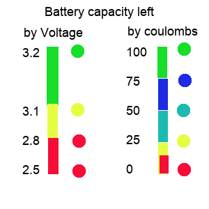 < Capacity methods
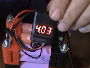 Cell loggers check voltages and Coulomb counters check Amps

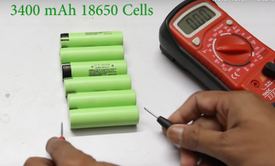 Fully charge all batteries and let them rest for a least 5 minutes then measure them so that you make sure each row has identical voltage. Ideally you also need to chart internal resistance and here is how.
Internal resistance
Make a spreadsheet for your cells. For each cell measure the open voltage and record it. Pick a resistor and record it's read value. Put the resistor across the cell ends and measure the voltage across the known resistance. Record this next to the battery it refers to. V=IR so I=V/R. With the now known voltage across the resistor and known resistance we can calculate I. And knowing I, we can use (Vopen -Vload) / I = Rinternal. So for each cell record the Rinternal. Any cell with a high internal resistance will not work well in a Gcell. Are you sure you can trust a Gcell was tested properly and balanced properly before you got it?
Before you begin making the packs it is important to closely measure the voltage of each cell and group them such that all cells per Gcell read the same. All cells in a parallel bank will gravitate towards the weakest cell's voltage. This makes it difficult for the BMS to level out the batteries consistently.
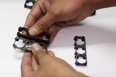
 Build your forms to accommodate the Gcell arrangement. In our case for a 12” x 7” x 6” Gcell we can go with 4 cells x 6 cells x 2 forms and 4 cells x 6 cells x 2 forms. For 32700 cells the forms are 1x2 or 1x3. If we connect 2) 1x3 end to end and do 4 rows of that we have 1 form made. We repeat form 2, then connect 2) 1x3 end to end and 4 rows of that we have form 3 made and repeat for form 4. Observe polarities ! All 6 columns in a row must be all (+) down or all (+) up. Row 1,3 should be (-) down, with Row 2, 4 being (+) down.
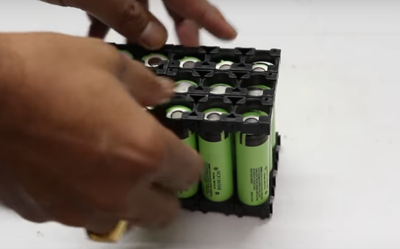
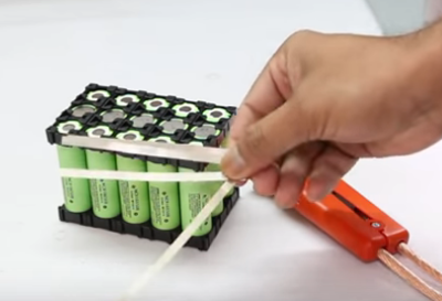 Once all cells are in place secure the top frame. We now need to cut tapping strips in Preparation to wire the cells. Remember these cells are fully charged.

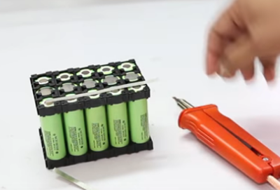 We will connect all (+) in each row together (Parallel) and connect short Tapping strips between (+) and next rows (-). Row 1 (-) also gets all 7 columns connected. Each (-) row gets a Tapping strip with a wire on for the BMS and row 1 (-) get heavy wire to (-) terminal, Row 5 (-) gets heavy wire to (+12v), Row 8 (+) goes heavy wire to +24v
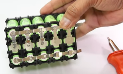 This example shows (+) row with all columns connected in parallel and in series with next row. In this example row 1 (-) is (- pole), row 1 (+) has (+3.2v) . Row 2 (+) connect all (+) together and all (+) wire to row 3(-). And row 3 (+) all connect together and a wire to (+9.6v) as this is a 9.6v Gcell with a 3,2v tap.
Since the topic of high currents of the battery packs has been mentioned often, we need to address it. Lets say our Battery source is 24v @ 60A like we have. From the research on handling high voltage and current they make a very valid point. It is highly dangerous to have a power source over 100A continuous and in many jurisdictions it is even criminal. Most people own a car of some sort. It has a battery that is usually 65Ah or higher and this battery also has another rating 800 to 1500 CCA which refers to cold cranking Amps. Since the CCA is used only during the starting, it is deemed non-continuous and safe. Our 72A pack follows the same guideline. During the 1/120th of a second at motor start it draws 250A but then draws beteen 0 and 5A depending on load and speed. The DIY sites abound and talk of 600A to 1000A systems. They are talking about the current used over the whole range to travel not the typical current draw at a moment in time. If it were over a moment in time the maximum range would be maybe 2 miles. It is over the whole range. so if you have 56 mile range, and it uses 560A to do that range, you are using 10A per mile. and if you are doing 60mph then you are using 10A per minute. Looking at AC induction motors, they are normally listed by wattage not by current.
Why an E-Trailer?
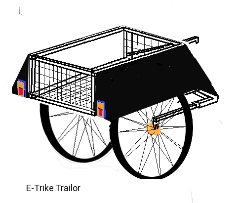 Frankly, being a frugal guy I like nothing to go to waste. We had it in the plans to buy a trailer for our E-Trike at $129 plus adding lights. The pre-made trailer was kinda lame at 21”sq basket. In making an E-trike we have 3 frames of carbon fiber or lite aluminum, 6 tires. 3 handle bars, 3 pedal sets, seats, chains, and sprockets. Surprisingly, I need one front of frame forks, 1 handle bar, 1 pedals sets, 3 Sprockets, and 2 tires. Remember the front wheel will be
electric if I stick with the plan.
Frankly, being a frugal guy I like nothing to go to waste. We had it in the plans to buy a trailer for our E-Trike at $129 plus adding lights. The pre-made trailer was kinda lame at 21”sq basket. In making an E-trike we have 3 frames of carbon fiber or lite aluminum, 6 tires. 3 handle bars, 3 pedal sets, seats, chains, and sprockets. Surprisingly, I need one front of frame forks, 1 handle bar, 1 pedals sets, 3 Sprockets, and 2 tires. Remember the front wheel will be
electric if I stick with the plan.
So basically most of the frames are waste, 2 seats and 2 handle bars too. Carbon Fiber and Lite aluminum can't be welded by most welding shops as they need a low power tig welder. So this got me to thinking what can I do with 4 extra wheels, and so much frame parts. The trailer I was going to buy was basically a 21 inch square basket with canvass cover, two smaller 14 inch wheels, and a pivot bar attaching to the seat-back.
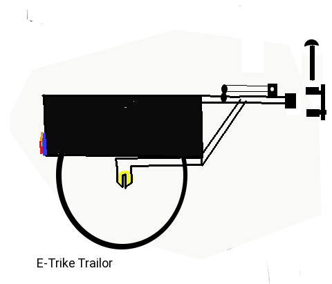 Which came first the Trailer or the Trike??
If you said Trike you made a mistake. Correctly, the Trailer comes before the Trike when designing things. This is important when you think about using front wheels as trailer wheels. Front wheels are designed to rotate smooth but have a different dropout spacing than rear wheels. Yes we can re-use the front forks but, and there is always a but, how can we weld them to the rest of the trailer framing!!
Solution is to Just make the frame out of nice weldable square tubing. For the dropouts, we can fashion them from 1/4th inch steel flat-bar and therefore have full control over how we make the flame. True we aren't re-using any of the bike parts yet. At this point I didn’t even have one bike. We can re-use one handle bar on the trailer tongue to give us the ability to detach and use it as a hand truck.
The wheels are 26 inch so the hubs are at 13 inches and we need 2" clearance for attaching them. So for our design we have the base of the basket at 15 inches from the ground. The basket must extend up at least 12 inches so the top is clear of the top of the tire. So our trailer top must be at least 27 inches from the ground.
The trailer needs to be slightly narrower than the trike. So if the Trike is 46 inch wide we can make the trailer 10 inch narrower or 36 inches. With 3 inch wheel width compensation, the final basket can be set at 30 inch (wide) X 36 inch (long) x 12 inch. We can re-use one handle bar on the trailer tongue to give us the ability to detach and use it as a hand truck.. Wow! That matches the rough calculations I did for the Trike!!! I started thinking about the trailer for two reasons, one was to find a way to use up left over
materials and the other was over concern over how to weld carbon fiber or aluminum. Now I have a better Trike solution too. Make two complete frames One will end life as the trailer. The other will become the main frame for the Trike with some custom mods to both attach the front forks and add the functionality.
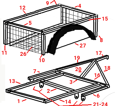 The Top of the basket is a steel frame exactly 30 inches by 36 inches outside dimension. To this frame we mount 4x 14 inch down columns (8-9-10-11). Using the 30 inch by 36 inch aluminum, cut 2 identical 15" x 36" panels and secure as (27). The front back and base of the basket is stiffened by the use of 1/8" aluminum rods weaved through mesh and bailing tied to the aluminum panels. This whole top section will then mount to the base assembly described to the left.
Looking at the chart above the most critical items are 21-24, 6-7, & 13-14. These pieces line up the wheel axles so they align straight. 1-2-3-13-14 must create a completely square frame 30 inches by 36 inches outside dimensions. Item 16 mounts flat against 3 with a 6 inch extension either side. When you know the exact clearance needed for the wheels, items 6 & 7 are secured to establish the spacing for the dropouts. Speaking of the drop outs. These you must hand manufacture out of the 2.5 inch by 2 inch flat iron. You need to know the exact diameter of the mounting bolt so a center slot can be made. We won't be mounting these dropouts until all other welding is done. That way they won't be in the way or get damaged.
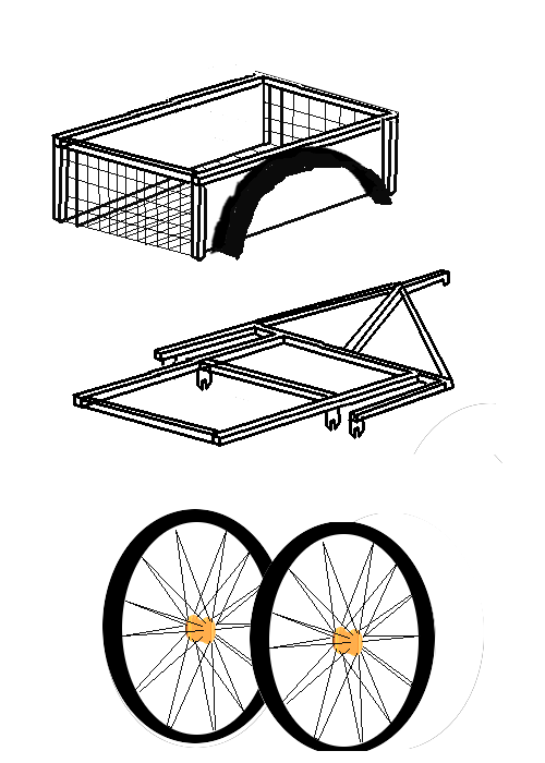
So here is what we need for the trailer frame,
- 5 x 1/2 inch Steel square tubing 30 inch long. (1-5)
- 2 x 1/2 inch Steel square tubing 14.5 inches long (6-7)
- 4 x 1/2 inch Steel Square tubing 14 inches long (8-11)
- 5 x 1/2 inch Steel Square tubing 36 inch long (12 - 16)
For the tongue we need,
- 1 x 1/2 inch Steel Square tubing 20 inch long (17)
- 3 x 1/2 inch Steel Square tubing 20 inch braces (18 - 20)
To mount the wheels and misc. we need,
- 4 x 2 inch x 2.5 inch Flat metal (21 - 24)
- 1 x Handlebar to be fashioned into fold down handle.(25)
- 1 x 36 inch x 60 inch wire mesh (26)
- 8 x 1/8 inch x 4 ft aluminum rod
- 2 x 30 inch x 36 inch 1/16 inch aluminum (27)
- 2 x Trailer combo tail lights (led) (28 - 29)
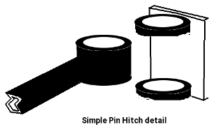
Hitch and Hand truck detail
Using a simple pin hitch is the easiest way to attach the Trailer to the bicycle. The part shown to right mounts on the Tricycle at the top of the Basket. The hitch ring is on the end of the trailer tongue. This tongue lines up with the top of the trailer basket and mates with the top of the trike basket. And when not in use on the trike can be used as a hand truck.
 No welding of carbon fiber or aluminum needed. at 10 inches from the hitch, (where all the braces converge) we weld two flat iron tabs and drill a hole thru them. Then on the bar comes from the handle bars themselves we drill a matching hole in the end. A bolt goes through the holes and is nutted as a pivot. When we pivot the bar out into position we need a hole to line up with the hitch so we can drop a pin in place.
Frame Detail
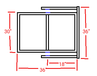
The lower frame is 30 inches wide and 36 inches long with dropouts centered 18 inches. Two out riggers 20 inches long with dropouts centered at 18 inches are mounted to the front bar such that precise wheel spacing is accommodated.
The upper frame is a a basic 30" x 36" frame with the tongue mounted center at 15" with braces down to the outside lower corners.
Options:
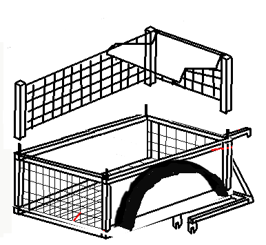 With the construction of the trailer thus far, we have an open wire basket without a cover or flanges for tail lights.
- Use 2 Carbon fiber or aluminum top rods to make sliding cover for the basket
- Use 2 carbon fiber or aluminum
top rods cut in half to make basket height extenders
The making of cover and extenders can take many forms. Here we have four (3 shown) with mesh or canvas between them and a roll-out canvas cover. If they were hinged instead of fitting over pins, they could act as a cover when closed or act as extenders when open.
Conclusion
With a little persuasion we were able to plan this trailer in a cost effective and feature rich way. We used two of the spare wheels, 2 top rods, 2 down pipes, and a handlebar. Waste was kept down to 1 handlebar, and 2 wheels (which might be just saved for another trailer) and two saddle seats. The original intended Trailer purchase was going to cost $129 for a 21" x 21" x 15" with 14 inch wheels bicycle trailer with 150 lb capacity and without a light package. For about $150 we can make this Trailer with the spare 26" wheels, give us a capacity of 30 inch x 36 inch x 15 inch with option to extend it to 30 inch height. Not bad! going from 5 cu feet to over 15 cu feet at double the load capacity.
Finishing Up
At this point we have the completed E-trike trailer with one exception. To be street legal we need full lighting package.
On the back of the trike, we must put a powered lighting connection and plug our trailer into this connector to supply lighting. Using the same tail light assembly with stop/signal/marker, our lighting is complete.
Bill of Materials
At the same time as we made the frame for the trike, we make the trailer frame so it's construction is covered with the trike.
Section
|
Item
|
Estimate$
|
E-Total$
|
Actual$
|
A-Total$
|
Basic Trailer
|
trailer
|
$0.00
|
$0.00
|
$0.00
|
$0.00
|
Lighting
|
(2) Brake light
(2) Turn Light
(4) Marker
|
$11.00
$10.00
$20.00
$20.00
|
$61.00
|
$
$
$0.00
$0.00
|
$
|
Other
|
Pop Rivets
Primer (1 cans)
Blue Paint (1 cans)
|
$3.49
$6.95
$6.95
|
$17.39
|
|
|
|
|
|
$78.39
|
|
$
|
Taking everything with you
So for the true off the grid experience we have this wonderful Solar electric Motor home configured for 17500 lbs of GVWR and made an E-tricycle with trailer for short running about and obtained a car converted to an EV but now we can’t go any-wheres. We have no hauler that will fit both the trike and car or either of them. We only have 6500 lbs to work with. Our Tricycle is GVWR of 250lbs with proposed trailer of 190 lbs. The proposed car is a chevy malibu at 3154 lbs. So our weight without a hauler is 3599 lbs. The hauler weight would have to be less than 2900 lbs.
E-Trike and trailer
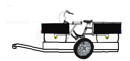 This trailer carries the E-Trike and trailer but has no option to carry the car. As a variation of a tow dolly it is about 650 lbs with a capacity of 1200 lbs. The GCWR runs 18,400 lbs. It is the only option that includes the Tricycle trailer.
Rooftop Carrier
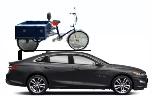 Modifying the roof of a car to hold the 250 lb E-Trike would make it possible to carry the E-Trike on the roof. A Blu-Ox hitch or similar would allow towing the EV-car behind the motor home changing the GCWR to 21,904 lbs.
Tow Dolly
 A tow dolly or dinghy towing a vehicle usually weighs about 600 pounds without a vehicle hooked up. This option can work for a car with or without rooftop E-Trike carrier. The GCWR becomes about 22,500 lbs. The tongue of the dingy can store under the front end or back end of the Motor home when not in use.
Car Trailer
 A car trailer can weigh anywhere from 1,500 to 2,800 pounds by itself. The average is 1,900 pounds. Again we can load the Trike onto the roof and load the car fully on the trailer. When at your campground the trailer needs a space of 36 ft to park. The weight of a car trailer largely depends on its construction, length and style. A bumper pull car hauler with length enough for one car may have a GVWR of 6,000 pounds. Additionally, aluminum car trailer weight and capacity will vary greatly from steel. On average, the load capacity for car trailers is 7,100 pounds.
Large Flatbed Trailer
 Large flatbed trailers, such as car haulers, weigh anywhere from 1500 to 7,700 pounds, even when empty. Again we can load the Trike onto the roof and load the car fully on the trailer. When at your campground the trailer needs a space of >36 ft to park.
What follows is making 2 types of hauler. First one is an E-Trike Hauler and the second one is a flatbed E-Trike and Car Hauler
Custom E-Trike Hauler
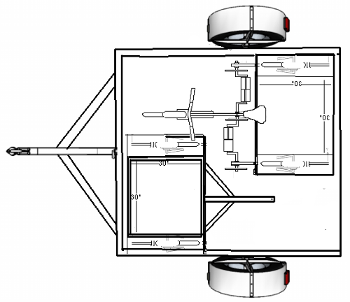
To be truly mobile we need to take all our stuff with us. So we need a Hauler to take our trike / trailer combo on the road. The trike and trike trailer are not that heavy so the hauler for them also does not need to be very heavy either. We have a basic flat bed trailer. We place the trike-trailer to the front and the E-Trike faces the opposite direction to the back on the opposing side. The handle bars would clear the trailer top so both fit on the small footprint trailer deck. Total weight would be under 400 lbs and likely would be closer to 300 lbs. Not shown is the required tie downs for the trike, trike trailer, and break-way chains to the tow vehicle.
Make a E-Tricycle Hauler
This one has no tilt feature but does have a lowered deck with small raised front and sides.
If you have never had or used a tow dolly, it is not for backing up the dolly or attached vehicle. In some places you can even get huge fines for trying to back up a dolly with a vehicle attached. You have been warned
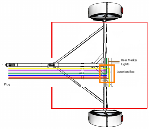 While legally speaking most jurisdictions do not require brakes on the tow dolly, it is advisable to include electric drum brakes at the very minimum.
This is a serious project with safety in mind. Don't ask if you can Print it on your 3D Printer, unless you are making a tiny model to display.
They are simple looking, function in a simple manor but are engineered to be strong and safe. They require competent experienced welders to assure they are made right and safely.
Once completed the tow dolly requires Wheel straps AND vehicle restraint chains to secure the towed vehicle. But
since we are going to haul an E-Trike and E-Trailer on the deck, the restraints must be adequate to prevent the contents from coming off while in travel.
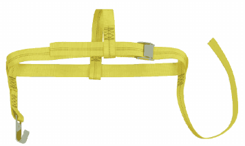 The preceding drawing were shown without the wheel straps (shown to the left) and the required safety chains. All dimensions are in millimeters (1" = 25.4mm)
Part one : Axle Setup
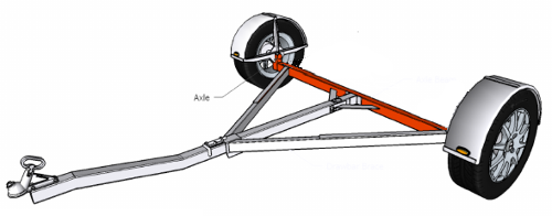 Setting up the axle takes a little bit of working out to ensure there is adequate clearance between the wheel guard and the top deck.
The details below are for a standard 39mm stub axle (1500kg) fitting which is in the majority of towing circumstances.
If using a larger stub axle check out and research using an overlay arrangement which among other things will require changing the axle dropper thickness from 5mm to 6mm.
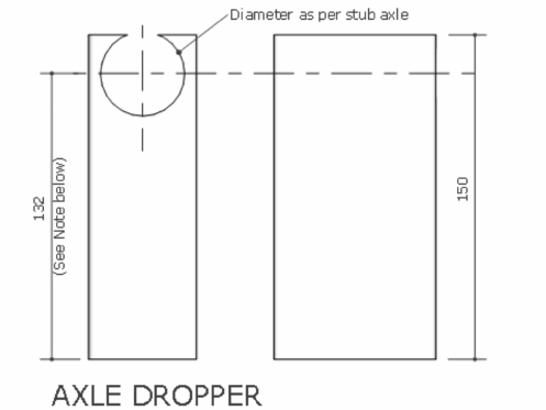
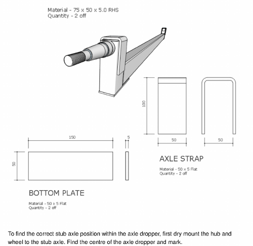
To find the correct stub axle position with-in the axle dropper, first dry mount the hub and wheel to the stub axle. find the center of the axle dropper and mark it.
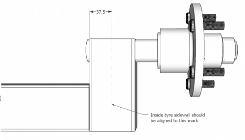 Slide the axle dropper over the stub axle and align the tire using a straight edge, until the inside wall of the tire is level with the mark on the axle dropper.
Mark or measure the axle stub position.
It may be necessary to trim the end of the stub axle so that a maximum of 10mm is protruding from the axle
dropper.
Once the stub axle has been fully welded in position, fit the axle dropstrap and bottom plate and stitch weld to
the axle.
Part two : Materials breakdown
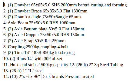
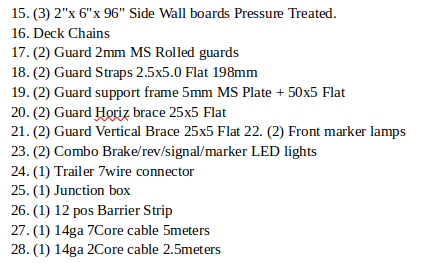

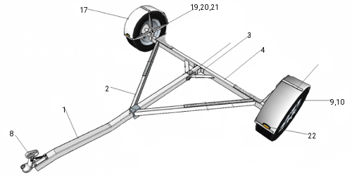
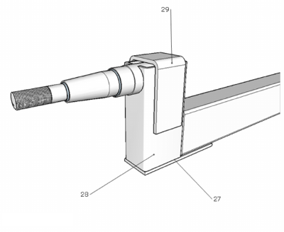
Section 1 : FENDER ASSEMBLY
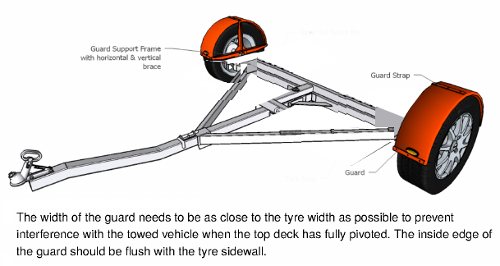 Setting up the guards is best done with the hubs and wheels fitted to the sub chassis. Because the trailer has no suspension to allow for, the clearance between the tire and the guard can be kept to a minimum.
The only requirement is that there is enough clearance for the lighting cables to run behind the guard with
sufficient clearance to prevent contact between the tire and cable and to allow small rocks and stones to pass between the tire and the guard without jamming such that they damage the tire and / or guard. 30mm to 40mm should be sufficient.
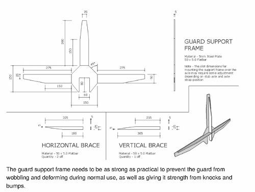 The guard can be welded to the guard straps, but as the guard is most prone to getting damaged, it is recommended that the guard is bolted on for quick repair or replacement.
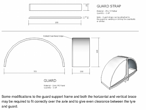
Section #2 : SUB CHASSIS ASSEMBLY
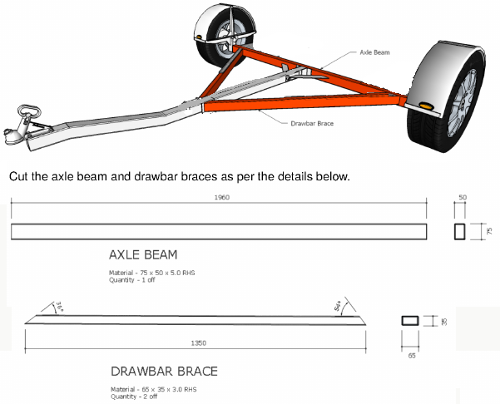 Set up all the sub chassis components as per the details to the left. Tack weld into place. Double check that the support tube is central and square to the axle tube. The Draw bar braces and the support tube top faces should be flush with the top of the axle tube. Be sure to fit the shroud end of the draw bar brace, flush with the draw bar and NOT the top of the shroud.
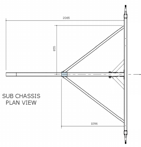 In a tow dolly we might make the dolly to fold for storage but since this will be a Flat deck trailer there is no tilt or fold and no ramps.
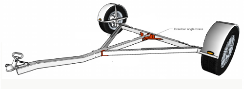
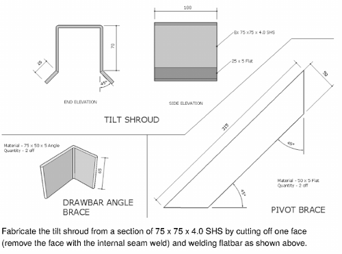
Due to the nature of this being a light duty trailer for E-Bike hauling, we don't need to make pivots, and really we don't even need the tilt shroud or the extra pivot braces. But for added strength here they are.
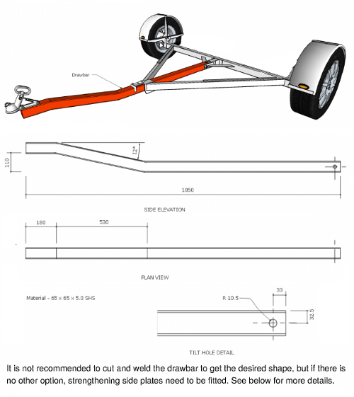
In this plan the tongue (draw bar) must be made correctly. If you lack the correct equipment to make it , it is preferable to get it professionally bent/rolled to ensure the integrity and strength of the hollow section is not compromised.
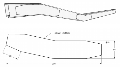 The side plates need to be fitted to both sides of the draw bar and stitch welded evenly around the plate. Stagger your welding to prevent any twisting or distortion of the drawbar from excessive weld heat.
Section #3 : LIGHTS
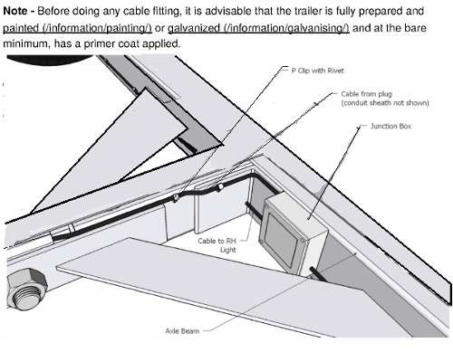 From the front of the trailer slide a semi rigid section of mild steel pull wire down the draw bar until it comes out at the end of the draw bar. Tape the trailer 4 lead cable (6 or 7 lead it fitting for electric brakes) to the end of the pull wire and pull from the tongue end until the cable comes through.
Pull the cable over the top of the tongue and cut once you have about 18" of cable protruding. Slide a section of flexible conduit sheath over the cable and pass it back over and into the gap between the tongue and the pivot support tube. Tape or heat shrink the conduit into place. This conduit will protect the cable from chafing on the steel under normal use.
** We are not making a pivoting or folding trailer but, and there is always a but, this is adapted from a folding tow dolly. In our case, we are not using the fold feature but
can use the fact that where it was supposed to pivot (we are welding permanent), there is a gap available for wiring.**
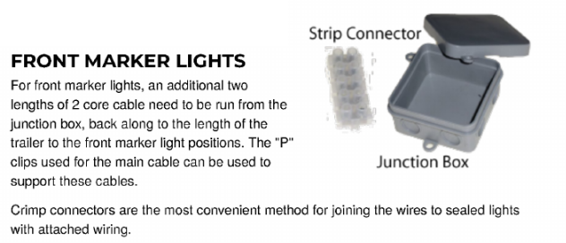 Drill a thru hole through the draw bar angle brace to allow cables to be threaded through to the right hand lights.
Mount a small junction box on the axle tube as shown in the drawing above and drill cable holes. Where possible use the correct size grommets to help seal the junction box from water and dust or dirt and to prevent chafing of the cables. Once the cables have been connected, use some silicon to fully seal around the cables.
Drill thru the back of the junction box to run a cable for the rear center marker lights (triple set)
"p" clip the cables to the axle beam and braces.
lights
Make sure that your number plate light is in the correct position and that the light will shine on the plate. Keep your lights as far to the outside edge of the guard as possible.
Mark out your light positions on the guards and drill cable holes as indicated for your lights.
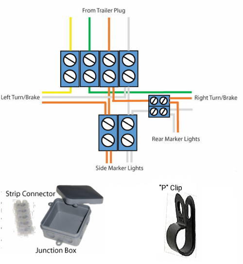 There are a number ways of joining wires together in a junction box but using a strip connector or barrier strip inside the junction box is one of the simplest and best way to keep connections secure and weather tight and also gives the option of easily changing lights should they becomes damaged.
Other options include soldering and using insulation (electrical ) tape or heat shrink tubing. Using crimp connectors and covering again with heat shrink.
They take less time but lack the ease of service if things go amiss.
Side Marker Lights
For side marker lights, an additional two lengths of 2 lead cable need to be run from the junction box. Take the cable along the same route as the main lighting cable, along the guard brace and behind the front of the guard. "P" clip the cable in appropriate hidden positions to prevent the cable from being snagged by either the tire or debris flung up from the road.
Crimp connectors are the most convenient method for joining the wires to sealed lights with attached wiring.
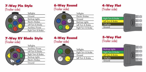 Pass the plug and cable through the hole drilled in the side of the draw bar and slide a suitable sized rubber grommet over the cable to prevent any chafing of the cable where it passes through the draw bar.
Trim the length of cable so that the cable can move
with the trailer without being stretched or kinked but not so long that it might touch the ground.
Slide any plug sleeve or casing that came with the plug over the cable, then strip each end of the plug wires leaving about 10mm bare wire, fold the bare wire ends
in half and enter them into the plug connector in the correct sequence as per the chart to the left. Tighten the screws snugly. Screw the cable clamp down to prevent the cable from pulling out.
Check all your lights by connecting them to the tow
vehicle trailer plug. Lights can be finicky, make sure the wiring on the tow vehicle is actually working before trying to solve trailer
light issues.
Section #4 : TOP DECK FRAMING
 The top deck is Constructed of 2" Square tubing built to a perfect Rectangle measuring 8 ft x 6 Ft. The 6ft width goes between the wheel wells. To the 2 " sq tubing mount a 1" angle iron flush with the bottom of the frame. At 24", 48", and 72" weld 2" Flat iron as shown. Do not mount the 13 1" x 6" pressure treated deck boards yet. Place the Deck Frame such that the center Flat Steel (@ 48") is aligned with the axle Beam and centered between the Wheel wells. Clamp in place and when you are sure the frame is square, weld the Flat iron straps to the Tongue, Draw bar Braces, and Axle Beam.
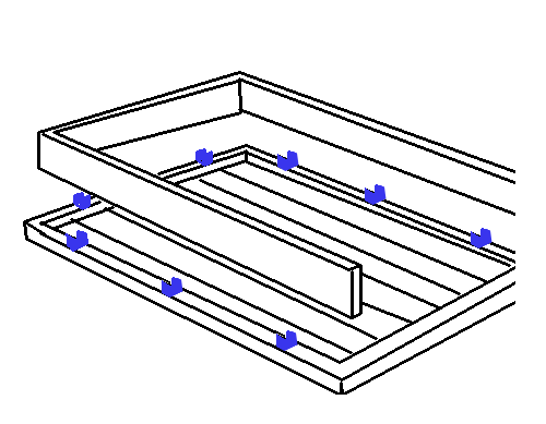 The Deck Fence is 2 x 8Ft 2x6 PT Lumber and 1 x 6Ft Trimmed to fit 2x6 PT Lumbar. They are mounted to Deck Frame as shown using 2" x 2" x 1" U-Channel spaced evenly. It is appropriate not to install the Fence until it is light sanded and painted. Also the deck boards should be finished with rubber coat and not installed until the frame
is painted and wiring complete.
The Deck Fence is 2 x 8Ft 2x6 PT Lumber and 1 x 6Ft Trimmed to fit 2x6 PT Lumbar. They are mounted to Deck Frame as shown using 2" x 2" x 1" U-Channel spaced evenly. It is appropriate not to install the Fence until it is light sanded and painted. Also the deck boards should be finished with rubber coat and not installed until the frame
is painted and wiring complete.
Section #5 : FINISHING
Fit the tilt bolt and nylock nut and secure tighten.
Grease and fit the bearings, hubs and wheels and torque the stub nuts up to these settings.
Torque settings for wheel nuts:
7/16" UNF 110Nm or 80 ft-lbs
1/2" UNF 125Nm or 90 ft-lbs
Fit amber reflectors to the side of the draw bar brace and fit safety chains and shackles to the front of the draw bar. Mount the coupling using good quality bolts and ensure they are torqued as per the suppliers recommendations.
Put a dab of grease on the tow ball and hook the trailer up to the tow vehicle and double check that all the lights are working. Grab a new vehicle registration from your local DMV or vehicle registration center, fill it out and license your new trailer. Attach your new license plate to your trailer and book the trailer in for a certificate of fitness if required. Once the trailer is licensed and
certified it is ready for loading!
After about 100 miles perform a check of all couplings and bolts, wheel nuts and guard strap screws. Do regular maintenance checks every 3 months of use.
Bill of Materials
Section
|
Item
|
Estimate$
|
E-Total$
|
Actual$
|
A-Total$
|
Framing
|
1. (1) Drawbar 65x65x5.0
SHS 2000mm before cutting and forming
2. (1) Drawbar Brace
65x35x5.0 Flat 1330mm
3. (2) Drambar angle 75x50x5angle 65mm
|
$23.00
$14.32
$3.49
|
$40.81
|
$
$
$
|
$
|
Driveline
|
4. Axle Beam 75x50x5.0 RHS
1960mm
5. (2) Axle Bottom plate 50x5.0 Flat 150mm
6.
(2) Axle Dropper 75x50x5.0 RHS 150mm
7. (2) Axle Strap 50x5
flat 250mm
8. Coupling 2500kg coupling 4 bolt
9. (2)
Tires 14" 185R 850kg load rating
10. (2) Rims 14"
with 30P offset
11. Hubs and stubs 1500kg capacity
|
$25.31
$4.16
$5.55
$11.21
$92.00
$124.00
$96.00
$76.00
|
$434.23
|
$
$
$
$
$
$
$
$
|
$
|
Deck
|
12. (26 ft) 2" Sq
Steel Tubing
13. (26 ft) 1" "L" steel
14.
(10) 2"x 6"x 96" Deck boards Pressure treated
15.
(3) 2"x 6"x 96" Side Wall boards Pressure
Treated.
16. Deck Chains
|
$48.00
$27.00
$30.00
$9.00
$19.65
|
$133.65
|
$
$
$
$
$
|
$
|
Wheel Guard
|
17. (2) Guard 2mm MS Rolled
guards
18. (2) Guard Straps 2.5x5.0 Flat 198mm
19. (2)
Guard support frame 5mm MS Plate + 50x5 Flat
20. (2) Guard
Horiz brace 25x5 Flat
21. (2) Guard Vertical Brace 25x5 Flat
|
$8.00
$8.00
$8.00
$8.00
$8.00
|
$40.00
|
$
$
$
$
$
|
$
|
Lighting
|
22. (2) Front marker
lamps
23. (2) Combo Brake/rev/signal/marker LED lights
24.
(1) Trailer 7wire connector
25. (1) Junction box
26.
(1) 12 pos Barrier Strip
27. (1) 14ga 7Core cable 5meters
28.
(1) 14ga 2Core cable 2.5meters
29. (10) "P" clips
|
$12.45
$20.76
$7.95
$9.65
$1.23
$5.00
$3.00
$2.40
|
$62.44
|
$
$
$
$
$
$
$
$
|
$
|
Other
|
30. Chain 2500kg minimum
rated 400mm long
31. Shackle minimum 2000kg rated
32.
Shackle washer
33. Primer (3 cans)
34. Blue Paint (3
cans)
|
14.55
8.95
3 *
$6.95
3 * $6.95
|
$73.36
|
|
$
|
|
|
|
$784.49
|
|
$
|
Custom E-Trike and Car hauler
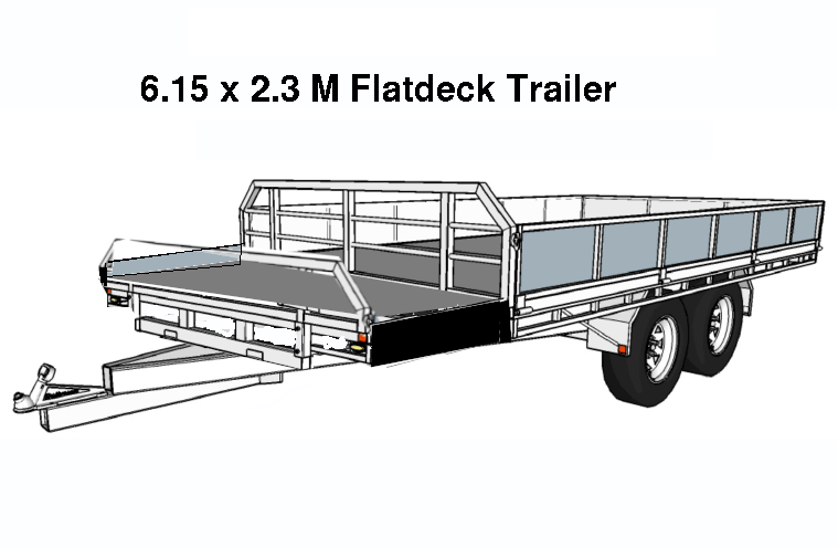 I have the plans for a 3.6M x 2M flatdeck trailer. Which I plan to modify to the image to the right. The original specs say 3.6M x 2M deck with 1100lb capacity if unbraked. 3500Lb capacity if braked.
As the plans state, it has folding sides, folding tailgate,
removable headboard. The deck needs to be increased from 11.7ft x 6.5ft to 20ft x 7.5ft to accommodate a car and the e-trike.
The reason for the length increase is so we can have a 4 ft space for the trike and a 16 ft space for the car. Width increase is because the Tricycle is 8 ft long and 4 ft wide (front wheel needs be turned a bit to close gate) and having only 3” to step on when car is loaded is not enough so for safety we will now have 9”.
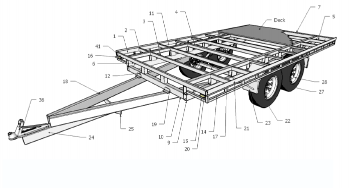

|
Specifications:
- Deck Size 3.6 (142") x 2m (79") increase 220” x 80”
- Tandem axle 14" wheels
- Oscillating load sharing suspension
- Fully welded steel chassis
- 17mm (11/16") Plywood decking
- Full length tie rails
- Fully protected front and rear lights
- Optional removeable headboard permanent
- Optional folding and removable sides and tailgate
- Tare weight unbraked 530kg (1170lbs)
Item 18 draw bar is 2500mm before modification, 3300mm for car mod only and 4100mm for car & E-trike modification. Items 1,2,9 increase by 1200mm, item 3 =9 qty, Item 5 qty +6 and 6” longer, item 6 & 7 is 12” longer.
Top Chassis set-up
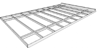
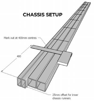
Outer runners increased to 16 ft from 11.7 ft
Inner runners increased to 16 ft – 50mm and offset 25mm at each end. Mark off 400mm centers for cross members.
|
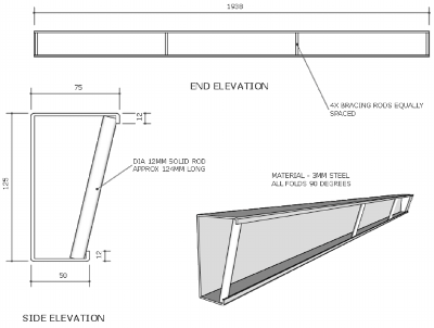
|
Cut and fold up light channel, as per the drawing, and pre drill for your lights if you already have then on hand.
Fit rod braces to the light channel, one each flush with the ends and the other2 equally spaced along it's length.
On a flat surface, Lay out the chassis runners, front cross member and light channel and tack weld into posistion. Check the frame for squareness and adjust.
Once the frame is square sandbag or clamp the frame to prevent any accidental movement (25kg bags of cement are perfect for this.) Fit all outer and inner cross members, centering them against the 400mm markings on the chasis runners.
|
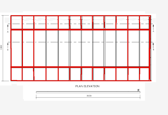
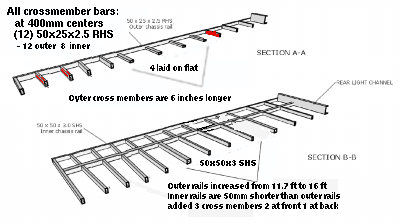
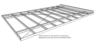
|
Where the outer cross members may reduce wheel clearance with the chassis, lay the RHS on it's widest edge flush with the bottom of the chassis runners. See the cross section picture left. Due to changing the width from 6.5 ft to 7.5 ft the outer cross members are 6” longer on each side. Due to changing the length from 11.7 ft to 16 ft the
inner and outer rails were lengthened.
For the inner cross members, note the position of the two 50x50 sections. These are used for joining decking material based on 1200mm centres. if your proposed decking material is different widths, you may need to alter the 50x50 SHS positions to suit.
Once all the cross members are in position tack weld in place checking the squareness of the frame. Measure diagonally corner to corner from identical positions
Where one measurement is longer, divide the difference between the two measurements and gently knock the longest corner of the frame to match the shortest side plus the difference in measurement.
For example:
if the shortest reading is 4100mm and
the longest is 4120mm, 20mm is the difference. divide 20/2 to get 10mm knock the longest length till the tape reads 4110mm. Keep adjusting till they both are identical. Clamp in place and sandbag until ready to weld.
|
The Sub Chassis

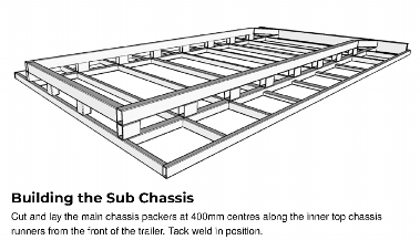
|
The sub chassis rails remain the same width as before to line up with the inner rails of the decktop the length of the rails changes from about 11.7 ft to 16 ft overall. We will now 24 spacer block instead of 18.
Cut and lay the main chassis packers at 400mm centers along the inner top chassis runners from the front of the trailer. Tack weld in position.
|

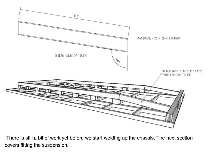
|
This isn’t to scale because we added 3 cross members and adjusted the size of deck. Note the last cross member has no spacer (pack).
The wheelwell / suspension is moved 1 cross member towards the front.
|
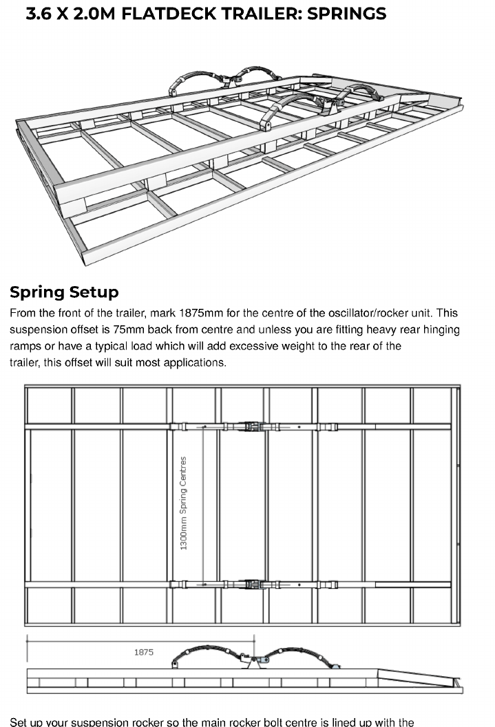
|
For 16ft trailer use 2675mm not 1875mm for center of oscillator rocker.
For 20 ft trailer use 3475mm not 1875mm
Adjust the spring so that the tail of the spring can move freely when the rocker oscillates without binding or dropping out.
Make sure that the outside edges are flush with the outside edge of the chassis rail and once double checked, tack weld the spring hanger and suspension rocker to the chassis rail.
Once this is completed on both sides, position the slippers over the spring rails allowing for clearance between the spring and the slipper for the spring to move in and out when loaded.
|
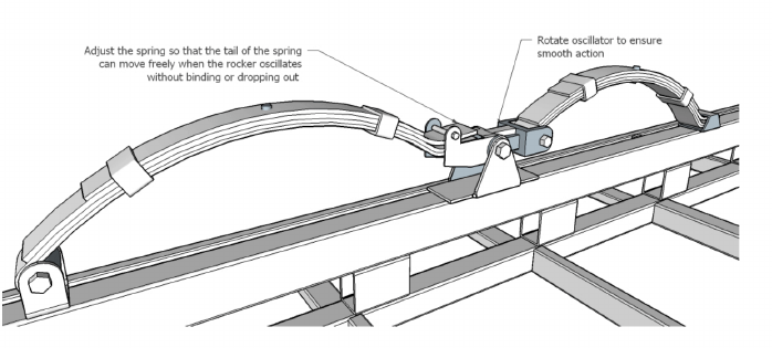
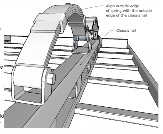
|
Again make sure the outside edge of the spring is flush with the outside edge of the rail and tack weld the slipper in place.
|
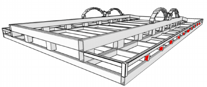
|
Once all components are in position, remove the spring and fully weld around the hanger, rocker and packers.
Now is a good time to measure up your axles.
|
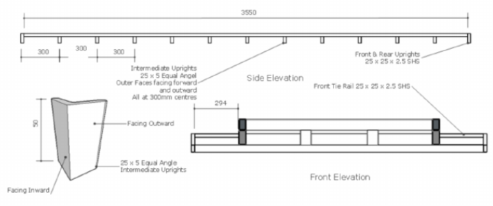
|
Fitting up the tie rails:
Tie rails are small angle iron pieces welded to the outer rails.
|
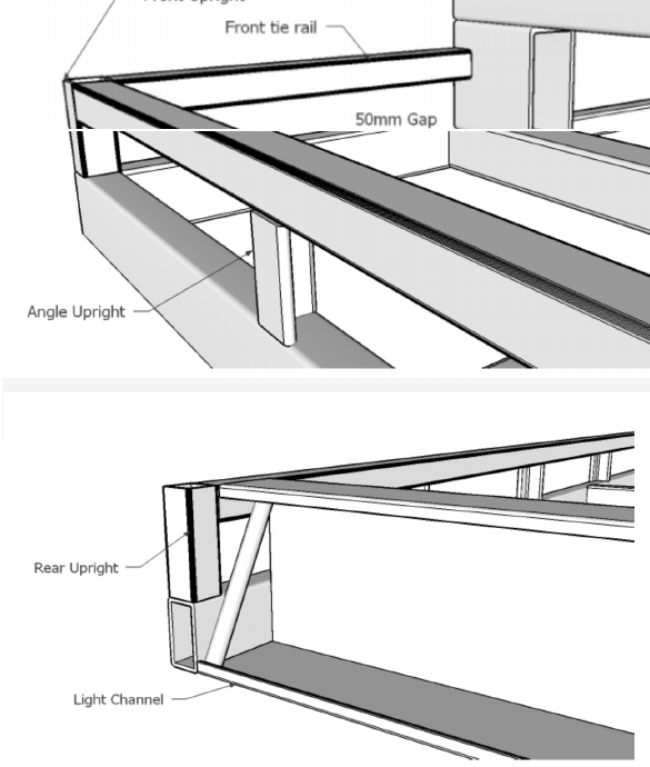
|
Measure and mark out along the outer chassis rails. 300mm centres starting 12.5mm in from the front of the deck to compensate for the first upright.
Fit the 25x25 SHS uprights and tack into position.
Position the 25mm angle uprights at the marked positions with the outer face flush with the outside edge of the chassis rail and the other facing the front. Tack weld onto the chassis rail.
Lay the tie rail between the end uprights and tack weld into position. Adjust the intermediate uprights to ensure a nice straight and level tie rail. Fit the front tie rails between the front upright and the chassis packer.
Make sure the tie rail is level and flush with the front of the deck and tack weld into position.
Once everything is tack welded into position, check for square and looking as it should. Fully weld up all visible components of the top chassis. It can’t be flipped over until the draw bar is in place. |
6.15 x 2.3 M Flatdeck Trailer tongue Components
This section covers the all important angle gussets which provide additional strength to the draw bar as well as preventing metal fatigue as the draw bar does it's work.
|
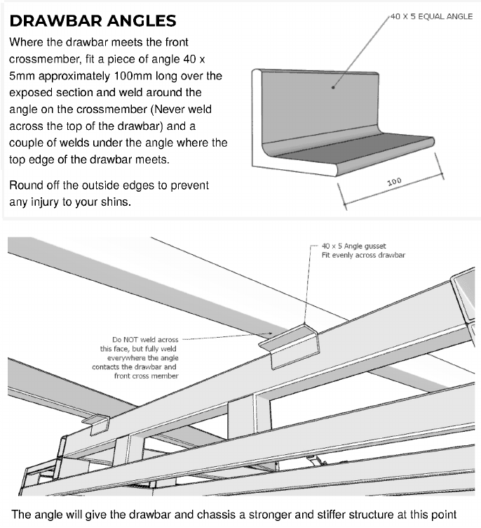
|
With the flatdeck trailer there are a couple of coupling mounting options and these are detailed below.
|
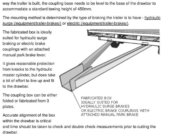
|
Coupling Mount
There are a couple of methods of mounting the coupling to the draw bar and due to The Coupling Mount
|
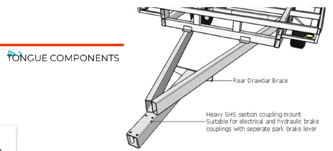
|
The second more commonly used option is fitting a section of 90x90x5 SHS under the draw bar, and mounting the coupling on top.
This setup is suitable for both unbraked and hydraulic braked couplings, as well as electric couplings with a separate park brake lever.
This style coupling mount is very quick and easy to build and fit, but care does need to be given to good quality welding.
Compression tubes need to be fitted with-in the cavity of the coupling mount to prevent the deformation of the SHS when the coupling bolts are tightened. A rear draw bar brace gives added strength.
Blanking off the open ends of the draw bar make for a nicer looking trailer.
|
6.15 x 2.3 M Flatdeck Trailer Fenders
Fabricating & Fitting Guards |
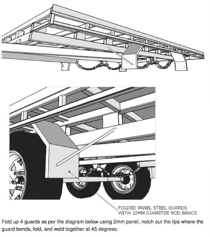

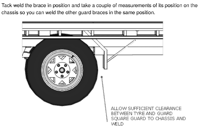
|
Get several friends to help flip the Flatdeck over onto jack stands It is very heavy with many sharp edges.
Once flipped, finish welding the top of the chassis and add the suspension and axles.
Fit the wheels and tighten all nuts and bolts on both the suspension and hubs.
Because we increased the deck width on both sides by 6” the guards must be placed against the inner rails . They should be welded across the top to the nearest cross member by using scrap metal if necessary.
|
6.15 x 2.3 M Flatdeck Trailer Trim
|

|
Marker lights
Cut out a couple of marker light plates to suit the size of your marker lights.
2mm Plate is suitable and can be pre-drilled for screws and wiring.
Weld the plate into position along the back side of the front tie rail and cross member for maximum protection of the light. |
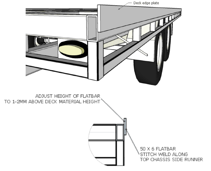
|
DECK EDGE PLATE
The deck edge plate gives protection to the decking material and gives a welding surface for hinges and the like. It should be 1-2mm higher than the decking and
stitch welded it's full length.
|
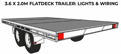
|
Note:
Before doing any cable fitting or wiring you must not have deck installed, chassis should be sanded, primed and painted. Once cabling is complete add decking material and
finish deck.
|
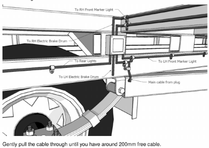
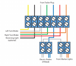
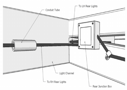
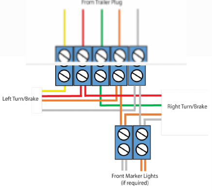
|
Running the light cable
From the front of the trailer slide a semi-rigid section of mild steel pull wire down the draw bar until it comes out an oversized hole drilled on the inner side in the draw bar close to the spring end. attach your 5 or 7 wire cable with
tape. 7 wire is for use with electric brakes. Pull the cable through the draw bar until 200mm is available at the front.
Allow another 600mm at the coupler end for wiring the plug. Fit a juction box just above the spring hanger and wire in the main cable. Run a 5 core cable from the junction box to the rear light channel and tee off (Lh & Rh) cable in another junction box.
Drill through any cross member or chassis runners not already drilled to allow clear passage of the cable. From the rear junction box the cable can pass through conduit
to the rear lights.
Whenever any cable passes through any steel work, apply silicon sealant, heat shrink, etc. to prevent cable chaffing.
|
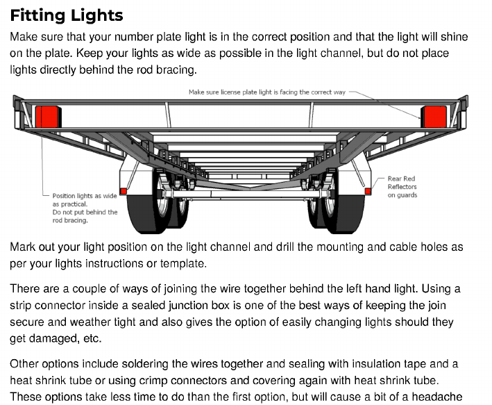
|
|
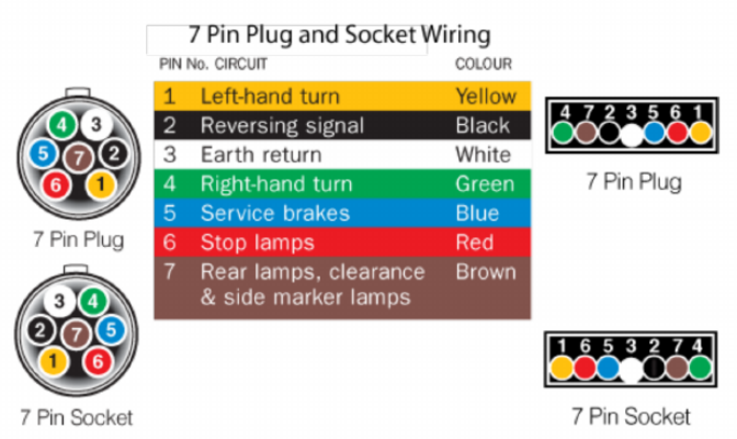
|
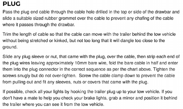
|
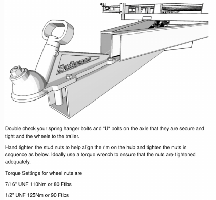
|
Ok if you made it this far you have a trailer with
a deck 16ft x 7.5 ft or a trailer unfinished with a deck 20 ft x 7.5 ft. For your 16 ft x 7.5 ft version you just need optional headboard and sides and ramps for loading and unloading. For the 20 ft version you will note that the draw bar is 2ft shorter protruding from the deck front. This is because to include the 4 ft of Tricycle storage up front we needed to come an extra 2 ft over the draw bar space. In the original the draw bar was connected at the front of the chassis and back at front of the spring at the frame.
|
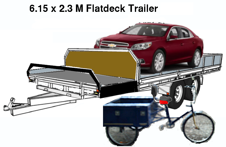
|
To complete the trailer we need to install U brackets at the front of the 16ft section and front of the 4ft section and along the back side of the 4ft section. The U brackets are 2” x 2” and will at the very least will support 2x6 or 2x10 pressure treated lumber to close in the space. A 2x6 hinged gate closes in the Tricycle area.
|
With the new car hauler trailer the draw bar is 800mm longer and attaches to the front of the deck which is also 800mm longer with deck size 1200mm longer than the original. The new dual purpose trailer shown above has
a deck 2419mm longer than the original 3566mm and a draw bar which is 1600mm longer fastened back at the rear axles, at the front of the 16ft section and at the front of the 20 ft deck.
Possibilities
The Tricycle is more stable than a bicycle which in itself means:
- easier to ride
- More natural upright position
- Better road vision
- 7.5 cu ft basket ideal for shoppin trips.
- 200 to 300 lb of cargo space
The Solar-Electric Tricycle surpasses being just a pedal Tricycle.
- 50 kph speed just like a car or truck.
- Street legal
- Base range of 68 kilometers.
- Can be recharged by Solar
- Can be Shore recharged in 5 hours.
- No insurance needed.$1000/yr
- No license needed$20/yr
- No expensive loans $5,000/yr payments reduces to $3000 one time fee
- No expensive maintenance costs$1000+/yr
- No oil changes $400/yr
- No gas or diesel to fuel it $2800/yr
For those who travel alone a Tricycle offers:
- Travel for shopping
- Travel for recreation or excercise
- Travel for Dining out
- Going to school
- Going to work
- Visiting
- Reaching appointments like Eye doctor, Dentist, Therapist, Doctor
Work applications too:
- "Skip the dishes", "Door Dash", Local liquor stores, flower shops, Pizza shops
- Postal delivery, couriers
- Prescriptions delivery
Enhancements:
- Add a 12v tap at batteries to provide car adapter port for charging cell phones, running a cooler/warmer
- Swap out 32700 batteries for 21700 batteries to extend range from 67 km (72A) to 71 km (90A)
- Extend range to maximum 222km (192A)
Conclusions:
In review of the statistical data obtained however so dated, it is clear that there is some premise for conversation on alternative energy.
 The 2003 published pie chart below shows 42% of Canada's electric energy comes from non-hydro sources. Wind and Solar is a mere 2% and combined with the 58% from hydro we can assume Canada is 60% earth friendly.
 By taking figures listed in the petroleum journal and mapping them on to the same pie chart shows something interesting. Non petroleum based solutions for supplying our heating and transportation is 18%. Another 6% (propane) might be used for heating and transportation but clearly 76% is Petrochemical and harmful to the environment.
 Mapping the figures from a bulletin on climate action needs substantiates the ones from the petroleum journal showing the exact same percentages as contributing to climate change through greenhouse gas production.
What this has to do with my report here-in, is a demonstrated need for efficient and economical move away from fossil fuels in favor of renewable energy to meet our transportation needs. So now on with my conclusions on an EV Tricycle build.
The subject of this evaluation was to develop a multi-function Tricycle. A Tricycle that is functional for youth, seniors, shopping, commuting to and from work, and even economical for those doing food and medicine delivery.
| Spec |
EV Tricycle |
EV Trike trailer |
Tricycle Hauler |
Tricycle / Car Trailer |
| Drive Train |
RWD |
n/a |
n/a |
n/a |
| GCWR |
891 lbs |
n/a |
n/a |
n/a |
| GVWR |
591 lbs |
290 lbs |
880 lbs |
5200 lbs |
| Wheel base |
68 in |
56 in |
n/a |
n/a |
| Motor |
Adapted Wheelchair motor
12 lbs. |
n/a |
n/a |
n/a |
| Transmission |
3 sprocket freewheel axle
9 lbs |
n/a |
n/a |
n/a |
| Solar Array |
29 lbs |
| Battery Pack |
2x Gcells 72Ah
2x 25.6v @ 36A 36.72 lbs |
| Curb weight |
171 lbs |
n/a |
n/a |
n/a |
| Payload |
420 lbs |
n/a |
n/a |
n/a |
| Range |
1.8Kw/0.054 = 33 miles |
n/a |
n/a |
n/a |
| Cost/mile |
$0.015/mile |
n/a |
n/a |
n/a |
| Upkeep cost |
$62.05/year |
n/a |
n/a |
n/a |
| Yearly cost |
$186.15 |
n/a |
n/a |
n/a |
Running lights for markers, signaling, brakes, will be 25.6v high lumens LED and this includes the headlights.
The cost of batteries $960 (unless price goes down) have a 15 year lifespan which amounts to $0.17 per day for eventual battery replacement. With the Tricycle having space of 3 times what has been used the potential of adding two more sets for $960 each ($2880) can extend range from 33 miles to 102 miles (170 kms).
Riding by pedaling aside, costs to recharge you from shore power will cost about $0.34 a day and take under 2 hours. But, and there is always a but, you can charge one bank while you ride using the other bank and both while you are stopped somewhere to shop or work.
In charge mode, the Gcell that are not in run mode become in charge mode. This takes advantage of a low cost 30v method of charging. Each 25.6v block has it's own BMS and is charge monitored for accurate results. Each cell has 6A capacity.
Therefore:
- 6 cells in parallel = 6A x 6 = 36A
- 8 cells in series = 3.2v x 8 = 25.6v per Gcell
- 2 banks in parallel = 25.6 @ (2 x 36A) = 25.6 @ 72A
- 25.6v x 72A = 1.842 Kw
As a single person vehicle it is great for short trips, exercise, and situations where you don't need that car or truck.
At $3,000 costs it has merit as a commuter vehicle.
In the future
When the price of 21700 cells is at or below the price of 32700 cells we will see considerable price and weight reduction.
This concludes the Solar
Electric Tricycle
Copyright 2023 ALL TECH DEVELOPMENT under Rick Beauchamp all rights reserved.