
Portable Raspberry Pi Computer
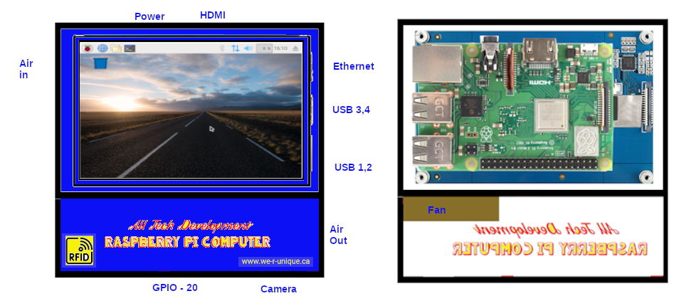
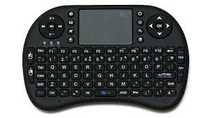
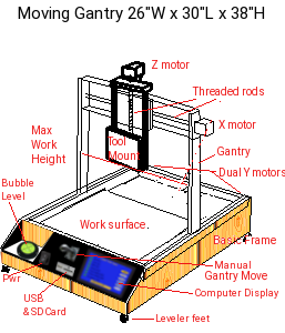
The Raspberry Pi 3b is a credit card size computer. In my application, I will be adding it to a 4.3 inch display and housing it in a custom case. The computer will be used in 4 modes of operation. The first mode is stand alone mode. Under this mode it will have external power, keyboard, touchpad, Camera, Harddrive, and optionally hdmi display and breadboard features. The second mode is as an E-trike control module that can run a Solar Electric Tricycle. Mode 3 is as a CNC controller for milling and 3D printing and finally mode 4 is as a 3D scanner.
 Applications:
Device use
Applications:
Device use
Applications:
Device use
Applications:
Device use
The case is made from blue Plexiglas pieces cut to size and bonded together using acetate glue. Careful placement of access holes to features allow it to fit into the Etrike, CNC, and 3Dscanner frames.

Fully assembled the unit is 4.88 x 4.95 x 1.5 inches. In the E-Trike application the top HDMI and PWR and Right side ETHO USB1-4 are hidden from access by the frame it fits into. The CNC and 3Dscanner
have provisions to allow access.
Special note: The image edges closest to the top mount to the top along the black lines. In this way the vents , GPIO and CAMERA are above mounting frames and all others are obscured by the frames.
Wiring the RPI is fairly simple. A40 pin GPIO connector connects to a breakout board. This breakout board has 2 pins to power the cooling fan, 3 wires to the RFID pcb with loop antenna and a 25 pin D socket. A 15p FFC cable comes to an ffc socket on another pcb with a 15p D socket for a ccm camera.
Everything to wire this up fits in the case as shown except the ffc breakout module. To make this module fit it has to turn verticle because
 the inner wall is in the way of it fitting horizontal. The perf board to interconnect the wiring also will need trimming around the fan.
To complete the portable raspberry pi 3b computer, we add a base plate with edge tabs for screwing it into place.
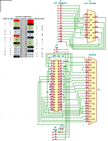
To the left is the wiring chart and schematic diagram for the system. At the top we need to convert the ffc-f cable into a 15pin camera connector. Below that we have the GPIO20 (GENERAL PURPOSE INPUT / OUTPUT connector) wired to a 25pin D connector and to a fan tap and
rfid connector.
Bill of materials:
Copyright 2023 ALL TECH DEVELOPMENT all rights reserved.
Portable RPI battery pack
The Raspberry Pi portable computer needs a battery pack to be really functional.

The case matches the RPI case in size and pieces only this time 3 batteries 32700 type lithium with their mounting take the place of the RPI and display. In the lower connection section we have an on-off-on switch, a power jack and the DB25 female connector.
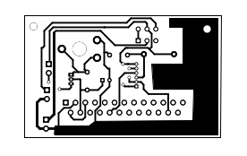
The circuit of the lower section contains a coulomb counter, and regulated power supply.
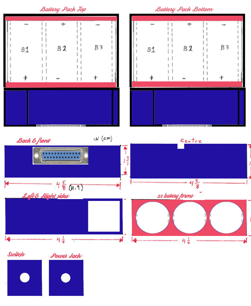
At the right we have the piecing layouts to make the battery cabinet. Once we have the enclosure we have to populate it with the electronics. Below left is the circuit diagram and to the right the circuit board.


3 Lithium ion batteries provide 9.6v @ 6Amps to a 3 position toggle switch. This switch is run mode , off , charge mode. In run mode, the batteries supply power to a 5v regulator circuit which passes that power to the computer through the 25 pin Dsub connector. In charge mode a 9v ac adapter provides power to the computer and the charge circuit. In both cases the computer reads the Coulomb counter to know whether the batteries are being charged or discharged. It disables charging when the batteries are full and does a shut down when batteries are depleted. Without the battery pack connected the Raspberry Pi can be powered by the usb type c connector or by connecting the RPI with it’s Dsub connector to the tricycle, 3D scanner, CNC machine or electronic breadboard attachments.


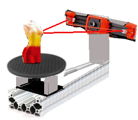
We now have a viable portable Raspberry Pi PC which is every bit as functional as a laptop PC but with capabilities that no laptop can do on it’s own.