Preface
 Hello, My name is Rick Beauchamp a former electronics, computer hardware and software engineer with some 40 years experience. I operated under the trade name All Tech Development. I come to you with a series of books focused upon moving to a Electric Vehicle society from the former Fossil Fuel one.
With the ever looming climate change due to use of carbon producing processes, we all need to consider alternatives that help the planet instead of hurting it. Insects and Animals and even Marine species adapt to their surroundings as much as possible, but man kind is like a virus, it consumes and changes the environment to meet it's needs. Because of these alterations it affects the natural state of the planet and the planet is fighting back. If it doesn't fight back, Earth will become a barren chunk of rock devoid of all life.
Hello, My name is Rick Beauchamp a former electronics, computer hardware and software engineer with some 40 years experience. I operated under the trade name All Tech Development. I come to you with a series of books focused upon moving to a Electric Vehicle society from the former Fossil Fuel one.
With the ever looming climate change due to use of carbon producing processes, we all need to consider alternatives that help the planet instead of hurting it. Insects and Animals and even Marine species adapt to their surroundings as much as possible, but man kind is like a virus, it consumes and changes the environment to meet it's needs. Because of these alterations it affects the natural state of the planet and the planet is fighting back. If it doesn't fight back, Earth will become a barren chunk of rock devoid of all life.
We are on the brink of big changes. Together, we will be covering the issues being faced in the next 26 years as we go to Net Zero by 2050:
- Federal Government Timeline plans and how it will affect people.
- Provincial Government fear mongering to impede progress.
- 34 million vehicles in Canada and 440 million vehicles in the USA must be replaced by 2040
- The need for new industries with improved standards.
- How conversion of vehicles to EV is less expensive and better than Buying an EV from Auto makers.
- Re-thinking how the Auto industry does things
- New business models for existing business
- Steps you can take to improve your home life
- Complete documentation on converting a vehicle to EV
This book is because our long time trading partner (the USA) has got a new president threatening our country with destructive tariffs. Climate change is real. It was predicted back in 1958 by the worlds top scientsts, spoke of by scolars and inventors like Thomas Edison and Alexander Graham Bell in the mid 1800's, and even forseen by fiction writers like Jules Verne.
The imagination of fiction writers have shaped our lives for real. Your cellphone, kitchen appliances, power tools, cars, airplanes and submarines were all once just fictional devices in stories.


Dedication
I Dedicate this book to my parents whom enjoyed the RV Lifestyle and
were inovators who never said it couldn't be done but embraced getting it done.
We would also like to dedicate this book to all those who dream of going the RV
lifestyle and maybe just need a little help along the way.
Climate change and Historical Data
Back in 1958 the worlds science community predicted that life expectancy of planet earth is about 150 years unless we take action against the harm we are doing to this planet by use of fossil fuels, coal, mining, and forest destruction. It was adopted by 150 nations that we will end Coal production and use as a fuel source by 2000, use of fossil fuels by 2020 and have green technology in place by 2020 so that our energy production and transportation is from renewable energy sources. Strip mining and deep earth mining will be regulated and managed such that such is done in a way to preserve habitat and forestry destruction will be halted as the trees make the air we need to breathe. It was further stated that earths population must not increase pass 7 billion as that is the sustainable level of this planet.
In the 1950’s society was mainly a re-purpose and reuse one. Our cars, trucks, vans were repaired, same with our tv’s, stereos, phones, appliances. Clothes were well made and became hand-me-downs, there were paper bags and cardboard boxes and nothing of plastic. Land fills were primarily organic waste and wrecking yards were the cheap source of parts for our cars with cars crushed after all re-use-able parts had been removed.
By the year 2000 almost nothing had been done on the recommendations agreed to by 150 nations. In fact things got worse. We had transitioned to a throw away society. Most things made from plastic. I come from the electronics industry. Back in the 1980’s I repaired tv’s, stereos, phones and appliance shops repaired appliances. We the country out sourced our electronics now. Nothing is repairable. There is a lot of hype about recycle but in fact recycle is just collect and store someplace else. We now have electric cars and yes they get in accidents like all vehicles do. But wrecking yards don’t understand about EV so they just stack them out of the way. Mining operations do now reclaim the area and plant trees and clear cut does do tree replanting too.
Political parties focus on the old popularity contest. One party does something good for the earth like trying to end coal production and use. Those who work the coal industry and those from the petroleum industry side with farmers who use the most coal to replace the government with a party that says we won’t end coal but will increase production, we will undo all the good the previous government did. As a people from our nation we should be ashamed. The world sees us more and more as uncaring, liars.
In review of the statistical data obtained however so dated, it is clear that there is some premise for conversation on alternative energy. The 2003 published pie chart below shows 42% of Canada's electric energy comes from non-hydro sources. Wind and Solar is a mere 2% and combined with the 58% from hydro we can say Canada is 60% earth friendly.
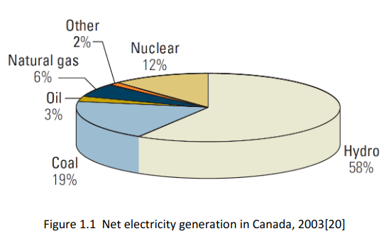 Canada sells off 30% of it’s overall electric power to the states and at any point in time may have 6% unused.
Certain grids may experience higher demand than is available from it’s local sources.
By taking figures listed in the petroleum journal and mapping them on to the same pie chart shows something interesting. Non petroleum based solutions for supplying our heating and transportation is 18%. Another 6% (propane) might be used for heating and transportation but clearly 76% is Petrochemical and harmful to the environment.
 Kerosine is the primary source for Air travel but the industry is starting to test solar electric jets.
Diesel and gasoline make up 58% of fuel use for transportation.
Mapping the figures from a bulletin on climate action needs substantiates the ones from the petroleum journal showing the exact same percentages as contributing to climate change through greenhouse gas production.
Hydro, wind and solar are 100% clean, natural gas and Propane are 80% clean and nuclear would be clean if waste could be dealt with. The 3 remaining are not clean. Coal isn’t on the chart but is the most harmful of them all. Thankfully it is the least used @19%.

What this has to do with my report here-in, is a demonstrated need for efficient and economical move away from fossil fuels in favor of renewable energy to meet our transportation needs.
Federal Government
Canada and the USA governments have set emmision targets of being Net Zero by 2050. This means all heating, production and transportation must be from renewable resources with serious cap limits on carbon producing processes. Primary Pollution contributors must pay a levy to cover their inaction to cleaning up pollution they cause. This is to force industry to take responsibility for damage they are doing. Because the general public have no control over the pollution from their cars they get a small rebate on the levy which was charged at pumps which they could totally avoid if they use an EV.
In addition, they have set targets of having all New vehicle sales being EV only by 2030 and all vehicle sales to be EV by 2035 and all Fossil Fuel vehicles removed from the road by 2040. So in 16 short years an estimated 34 million Canadian vehicles will be junked. In the USA 440 million vehicles will also be junked. Just like Industry is being made shoulder the burden for the emisions they cause, the vehicle owners are forced to shoulder the cost to replace their vehicles with EV. With Trump now as president it is uncertain what he may do.
In communication with the government's Science, Technology and Innovation I have learned there are grants, loans, partnerships available for entrepreneurs wishing to develop new industry.
Industry
The oil and gas industry is taking steps to do carbon capture and store, and improve production standards. As demand for fossil fuels is reduced, emissions from production will go down. The oil and gas sector is NOT going away. They will still be making lubricants, natural gas, and propane which by the way are clean burning fuels, Many municipalities are converting their fleets from gas and diesel to propane and natural gas.
Auto makers are in their glory. About 500 Million sales in 16 years is a $25 Trillion dollars business. They don't care that 500,000,000 drivers have to shoulder the burden. Nor do they care about the vehicles going to junk yards. And since vehicle batteries are in huge packs and difficult to deal with they can see a repeat of $25 Trillion dollars or more every 15 years as drivers will probably look to replace their ride instead of replacing battery packs.
Local Government
 The current Alberta government makes no sense IMHO. Here in Alberta the provincial government seems to see Albertan's as their private piggy bank. Here in Alberta we have coal fired power plants, Natural gas power plants, diesel power plants, Wind farms, and Solar farms. During the summer last year we had a power crisis because there was not enough power to support demand. What they didn't tell you was Alberta Energy shut down several power plants for maintenance (coal and diesel) resulting in lack of power. In the past few years they have aimed to
- take control over contributions made by hard working Albertan's to the national Canada Pension plan like Quebec did. They want to set rules over how much pensioners get, and seem oblivious to the fact that the population of Quebec compared to Alberta would mean fractional returns.
- We had a rainy day fund known as the Heritage Fund to support us when oil and gas revenues were no more. The former PC local government which is now called UCP squandered that all away.
- Did we really need a 1 billion dollar jet that was only used to ferry the premier's daughter and her classmates to a vacation?
- Or how about a million dollar apartment nick-named the sky palace.
- The NDP put a carbon levy in place which was in keeping with the federal plans but the UCP cancelled it so we are now under the national plan. The UCP took the government to court to stop the levy and lost.
- The current focus of the local government which relies upon high oil and gas prices is so blind. The Oil and Gas industry is strong and very rich. True they need positive ventures to new markets, but not at the expense of everything else. The local government has cut funding to education, health care, roads, power distribution, and new industry.
- They are wasting money on ads like "scrap the cap" to empower Albertan's to get oil and gas caps on emissions removed. The oil and gas sector is fine with the caps. But because Alberta uses fossil Fuel at some of it's plants and coal at others they have to pay their costs. They have wasted more money in ad campains and court challenges than a single geo-thermal power plant would have cost (geo-thermal is non-polluting).
- "Alberta launches national ad campaign opposing federal electricity regulations – September 28, 2023." WHAT?? a province that has spent 19 million on ads this year can't use it's "in Alberta. More than 388,500 MW of geothermal generation potential remains untapped, which is approximately 24 times Alberta's total installed generating capacity in 2019".
- "Concerns over Alberta government's 'Tell the Feds ..." where home owners are seen putting back groceries, deliveries disappearing, food on table vanishing all because businesses couldn't afford to run. It's plain idiocracy! Alberta has just shut down it's last coal fired plant that produced 15% of emissions but only 2% of power, on the green side 15% comes from solar and wind, 0.5% from geo-thermal (alone geo-thermal could produce 24 times what our entire power grid uses). Unfortunately the province gets royalties from oil and gas so wants to use natural gas in most of it's plants. This is why Alberta pollutes the most. 85% of Alberta emissions is from oil and gas sector. 60% of that is for power generation. So to answer : turn on geo-thermal full, shut down all natural gas plants, build a second geothermal for the future. Now the power grid has enough power for Electric vehicles, homes, work places, and if that isn't enough encourage home owners to get rid of gas operated water tanks which run 24/7 for Instant electric hot water units that run only as needed.
- Another possibility is to persuede home owners to install solar panels on their homes with storage batteries. Home owners can save 30% on their electric bills.
While most of this is targeted at convincing people to worry about not having power for their homes in times of need and helping the rich Oil and Gas industry opperate with less restrictions, it is also targeted at convincing people not to buy electric vehicles because our grid can't handle the load.
Political Change
This is scary on both sides of the border with the USA. Trump is an advid "Climate change denier", what will he do? He says the USA has been subsidizing Canada because he has to pay for our products instead of getting them for free. Then he refers to our prime minister as Governer of the next great state Canada and is planning on a 25% tax unless we stop drugs, and imagrents from entering his country. While this is going on Trudeau is fighting with internal feuding in his caucus. The National PC party is poised to have a non-convidence vote to force an election. Alberta has more legal battles planned with the Federal government.
Team Canada
Hurrah, Our Prime Minister has rallied all the Provincial leaders into a massive united fighting force. He works dilegently to deal with Trump. On the table is plans to eliminate provincial trade barriers to promote roughly 200 billion in GDP increase. Also plans to diversify Canada with alternate markets so we don't need to rely on the USA at all. Trump wants to absorb Canada so he can have all of the north west hemisphere under his control. The USA is 36 Trillion dollars in debt, spends more than it's GDP each year. Each citizen owes 76 billion dollars if we don't count the 2 Trillion it has in natural resources. Canada has 200 billion in debt with 15 Trillion in natural resources and a debt load per person of less than $5,000
So what now?
Lets keep Canada great. Instead of doing tit for tat Tariffs, each time the USA hints they might impose a Tariff respond with an immediate Tariff but don't clue them in until it is in place. Keep Trump guessing. Like Trump made demands that we secure the border which was actually his job to protect his country, we can demand he stops the illegal gun imports to our country, and illegal drugs as condition to Tariff removal. We have 34 million vehicles by 2040 that must be replaced on the backs of our citizens but, and there is always a but, why scrap all those vehicles when we can convert them to solar EV at a fraction of the cost. What person wants to pay $40,000 or more for an EV that can be converted for under $20,000.
Climate Change
In 1958 the scientists said we will know the end is near when huricanes, tornadeos, floods, droughts, earthquakes, and wildfires become a daily occurance in the news. I think we have seen all of these.
Entry to a New Era
 Planning for this is being done but we definately aren't there anytime soon. The following could have been done 20 to 40 years ago but as usual our leaders were scared of being voted out so they did nothing.
| Who wants what? |
| Who wants | Desired | How to be accomplished | Time frame |
| Federal Government | Net ZeroLevel 3Level 2Level 1 | All heating,production,and transportation by renewable resourcesAll Fossil Fuel Vehicles off the roadAll vehicle sales must be EV, All power production by renewablesAll new vehicle sales must be EVCarbon Levies Placed on Fossile Fuel Production, used for Electric generation and Vehicles | 2050
2040
203520302022 |
| Provincial Government | Net ZeroLevel 3Level 2Level 1 | We can't do it until at least 2100Our power grid can't support E-VehiclesThe levy is a TAX and we don't want to pay to make power. We make money from Fossil Fuel sales so it hurts the whole industry | 21002075205020352023 |
| Oil companies | Net Zero | Ok we will put effort into carbon capture.We are already working to use renewables | 2050 |
| Automotive Makers | Net Zero | Wow! of course we will do it.500 Million sales in 16 years and just as many every 15 years after. | 2050 |
| Businesses | HeatingFuelElectrictysuppliesLabor | More expensive and we need vehicles with range and capacity | |
| Consumers | FoodHeatingFuelProducts | more expensive, can't afford E-Vehicles | |
In the above table, the Federal Government has set the targets but shoulder none of the expense. That is passed onto Industry to meet the targets and pay a levy on emissions until they meet targets. Provinces that use Fossil Fuels for electric production like Alberta and Nova Scotia have high levy costs which they pass onto businesses and citizens in their electric bills. Those whom use Fossil Fuels for their vehicles also pay the levy rolled into Fuel prices.
Alberta Premier chooses to cry and fight through ads and court battles with the Federal government. Cutting programs and not putting any effort into meeting the goals. She has the tools through Geo-thermal to easily meet objectives but is like a spoiled brat just wanting her way. If she wants to run ads and offer input into things, how about telling Albertans' to replace the hot water heaters in their homes with Instant on demand electric hot water for an 18% reduction in Natural gas in the home. Instead of saying "No we won't do it" to the feds, ask for incentives of it's citizens that will continue to be an onging saving to all who do it. My propane run hot water tank cost me $30 a month to run. I replaced that with an Instant electric hot water that runs on demand for $200 and now hot water is $1 more on my electric bill.
The premier says Solar is unrelyable as is wind power. Both of these may cut in and out as conditions change, but solar panels on the homes can reduce energy needs by 30% a day and can be stored in battery when not needed for demand. It can even be sold back to the grid. People may have $60 electric bills which through solar may reduce their bill by $18. The Federal Government may be persueded to help with that too. In any case, the changes reduce gas costs to the consumer, and electric costs as well. With more than 1,633,220 homes in Alberta in 2021, I am sure that can put a dent in our carbon footprint.
The province makes royalties on Natural Gas, through some mechanism of commerce energy providers obtain Natural Gas and electricity and provide that to consumers along with the carbon levy in the prices. If consumers have a $60 gas bill and $80 electric bill, the province is getting $ 228,650,800 a month from 1,633,220 households plus royalties on Natural gas. The carbon Levy is being paid by consumers. Now if the consumers save $30 on gas and $18 on power they have $48 a month more and the province makes $78,394,560 less from citizens and earns less from royalties to service citizens but does achieve a lower carbon footprint.
The Auto Makers do things in a very poor way. When they build battery packs they use prismatic cells at 3.2v x 100A to 300A and connect them in series.
 This creates a very dangerous situation when it comes to servicing the pack. By the time you have connected 125 of these in series you have 400 volts at up to 300 Amps. You can't implement solar charging or bank switching or user replaceable Gcells (group of cells). Every manufacturer and model uses a different voltage and current (Amps). I suggest changing this. If we Standardize maximum volts to 384 volts. Break the voltage down to 48v (48 * 8 = 384) we have only 8 Gcells instead of 125 Gcells. Run these Gcells using a switchover circuit we can have solar charge capability, Gcells which are only connected to each other when power is on, and we can make them user replaceable. The Gcells would be the size and weight of a 12v lead acid battery but 4 times the voltage. "Canadian Tire or Napa auto" type operations could stock them. You can even use banks (8 per bank) to ease costs when cells need replacing. A vehicle can be converted to an EV far less than buying a EV from an Auto maker.
| Who wants what? |
| Who wants | Desired | How to be accomplished | Time frame |
| Federal Government | Incentives | Heat pumps - reduce heating costsReplace hot water tanks with electric on demand Install solar panels on homes and businessesEV Tax savings account which can be used to purchase EV or convert vehicle to EVSet standards for EV conversion and set standards for EV replacement Batteries | 2025 |
| Provincial Government | Natural gasGeo-thermalLess DemandLess Demand | Shut down these plantsTurn on the full capacity of Geo-thermo electric productionEncourage Electric instant on demand hot water and Heat pumpsEncourage adding Solar power for homes with storage batteries.Stop using our tax dollars to run missleading ads and pointless legal challenges. | 2025 |
| Oil companies | Net Zero | Keep up the good work | |
| Automotive Makers | Net Zero | Quit making throw away vehiclesRedesign vehicles for easy battery replacement.you will get a share in 500 Million sales in 16 years along with conversion facilities. | |
| Businesses | HeatingFuelElectricitysuppliesLabor | Lower heating costs with heat pumpsEliminated on in town travelSolar will cut costs 30%Might come down in cost Replace greedy workers and unions | |
| Consumers | FoodHeatFuelProducts | more expensive until shipping costs come downElectric costs will reduce, gas bill eliminatedEliminated on EVConversion costs are much lower and products will see reduction in price | |
The uncertainty and chaos introduced by Trump in the White House has really up-ended the game. Our democratic leaders seek to convince leaders wanting to impose tariffs that these will be bad for all. Bullies operate by intimidation and threat. Diplomacy does not work because they don't operate by democratic rules. Take the case, Trump says jump and protect your border from letting drugs and migrants come into my country or I will Tariff you hard on February 1st. So we deploy measures on our border at $1.6 billion. Trump says I will delay tariffs until February 4th. So we counter with tariff threat. Trump responds with giving a 30 day reprieve. 4 days later he places 25% Tariff on all steel and aluminum going into the USA effective March 14. Doug Ford called Trump an excellant negotiator. I beg to differ, he is a bully and a terrorist. Trump knows PM Trudeau leaves March 9th and the new leader takes over and will face non-confidence vote March 24th. My responce here would be to either stop all steel and aluminum shipmments to the USA until all Tariff nonsense is stopped or place 25% export Tariffs and do this immediately. We own the resources he lacks. If he finds that his threat has caused a major stoppage of things American he may see he has over reached as all Americans including his republican party worry about reprizals. If that is not enough Trump has stated that tariffs will be accumulative so steel and aluminum will hike to 50% in an attempt to destroy our ecconomy. So much for trying the democratic approach.
Going forward we need to remain focused. It is important to keep working on removing inter province trading barriers to boost our GDP by 200 billion. As we do this it is imperative that we seek new markets for our goods and replacement markets to obtain products. It is hoped that the EU and UK radify trade agreements we negotiated some time back. We also need new Industry and with my Auto conversion plan we can do a Made in Canada plan. Another option is to look into expanding pre-fab homes to target homeless problems and natural fire disaster rebuilding issues. Both of these can create jobs, improve our GDP and meet our climate change objectives.
 Our Premiers and the US citizens need to realize that there is no bargaining or deal making with Trump. He is just like Adolf Hitler was and the germans waited and found out too late. Back in the day Hitler used mis-direction and subtle inferance to change things just as trump is doing. While we are focused on trying to figure out his next move we aren't paying attention to our problems at home that can be used to Trump-proof our economy.
Chapter 1 Resource Choices
Going electric
To be able to be fully self sufficient we need the raw resources the capacity to manufacture everything ourselves and the workers to do the work. Our advantage is we have all of this and that is exactly what Trump in the USA doesn't have. He has workers and desire but almost no resources or manufacturing potential. That is why he is trying to kill our sovereignty.
- Steel yes
- Aluminum yes
- Lithium yes
- Uranium yes
- Copper yes
- Nickle yes
- Plastic waste yes
Because we are developing a new industry centered on vehicle conversion we could do it without buying USA made vehicles. I will be presenting real figures so you the reader can make educated decisions on converting your ride to an EV. Our target is to convert 26.6 Million current vehicles to Solar EV by 2040 and at 3% growth will likely be 34 Million by that time.
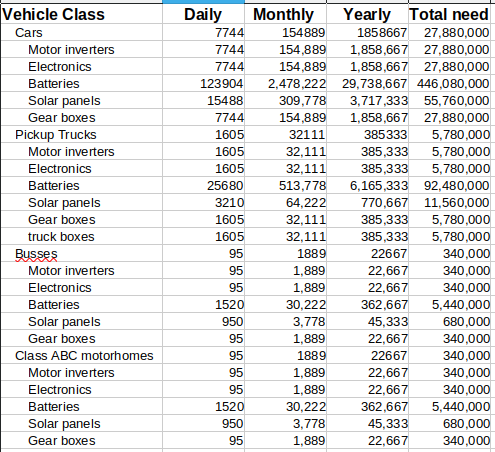 Here we have the volumes of conversions to meet our goals. As indicated the new industries will be busy for 15 years with no slow down as long as we can meet the demand country wide.
The demand for motors come in 3 classes. small light motors will do cars, slightly larger ones for pick-up trucks and much heavier ones for Busses and Motorcoaches. All motors and their matching inverters need to be rated 230/400 60 Hz at 3000 minimum RPM. Siemans, Motarvario of Italy and TMS of Quebec are potential suppliers as are the 100's of crashed EV cars in wrecking yards.
An Electronics devision will be in charge of making the universal control systems that consist of the display, Raspberry PI3 computers, ADC boards, Input boards and output boards, Charge boards, and Canopy boards. I have designed these.
The Battery devision will be in charge of making the 48v Gcells in 3 types depending on the vehicle class. Vehicles can start with 1 bank of 8 Gcells or 2 banks of 8 Gcells depending on customer financing. Home Battery storage for Solar panels may also be done.
The Solar devision will be tasked with making a set variety of 57v panels for use on vehicles and also for homes.
For front wheel drive cars the gear box is a modified transaxle transmission with the torch converter, hydraulic pump and valve body removed. The multiple clutch gears will be replaced with a single fixed gear. Trucks, Busses and motorcoaches will either be direct drive or use a single gear ratio box assembly.
Here we have the volumes of conversions to meet our goals. As indicated the new industries will be busy for 15 years with no slow down as long as we can meet the demand country wide.
The demand for motors come in 3 classes. small light motors will do cars, slightly larger ones for pick-up trucks and much heavier ones for Busses and Motorcoaches. All motors and their matching inverters need to be rated 230/400 60 Hz at 3000 minimum RPM. Siemans, Motarvario of Italy and TMS of Quebec are potential suppliers as are the 100's of crashed EV cars in wrecking yards.
An Electronics devision will be in charge of making the universal control systems that consist of the display, Raspberry PI3 computers, ADC boards, Input boards and output boards, Charge boards, and Canopy boards. I have designed these.
The Battery devision will be in charge of making the 48v Gcells in 3 types depending on the vehicle class. Vehicles can start with 1 bank of 8 Gcells or 2 banks of 8 Gcells depending on customer financing. Home Battery storage for Solar panels may also be done.
The Solar devision will be tasked with making a set variety of 57v panels for use on vehicles and also for homes.
For front wheel drive cars the gear box is a modified transaxle transmission with the torch converter, hydraulic pump and valve body removed. The multiple clutch gears will be replaced with a single fixed gear. Trucks, Busses and motorcoaches will either be direct drive or use a single gear ratio box assembly.
Cars will cost about $15,000 to $20,000 to convert, Trucks about $25,000 to $30,000, Busses and Motorhomes about 45,000 to 50,000. All in all it is a 760 Trillion dollar GDP over the 15 year span.
 As a vehicle, the owner has choices to make about your ride so here it is. A car is class A, A Pick-up is class B and Bus or motorcoach is Class C. It is desirable to use 21700 Gcells as they are lighter, smaller and thus easier to fit into the vehicle. You can start with 1 bank of Gcells and have shorter range of travel but less expensive conversion. You can add the second bank later for full range. Or you can do both banks at once. If your joe average that goes to work by yourself, or does shopping etc your daily use may be as low as 50 kms.
The most expensive part of conversion is the batteries.
As a vehicle, the owner has choices to make about your ride so here it is. A car is class A, A Pick-up is class B and Bus or motorcoach is Class C. It is desirable to use 21700 Gcells as they are lighter, smaller and thus easier to fit into the vehicle. You can start with 1 bank of Gcells and have shorter range of travel but less expensive conversion. You can add the second bank later for full range. Or you can do both banks at once. If your joe average that goes to work by yourself, or does shopping etc your daily use may be as low as 50 kms.
The most expensive part of conversion is the batteries.
Chapter 2 The Grand Plan
My grand plan began as a plan to convert my motorhome to an EV-Motorhome, augment this with a Solar-Electric tricycle for short commutes, and obtain a vehicle to convert into a Solar-electric vehicle. The intent was to fully document these ventures for others who may wish the same course of action.
Then suddenly came NEWS of the Canadian Government's climate action plans. I was doing my part to honor my mother's wish that I make my Motorhome into an EV and pass on my knowledge. It's no longer about me, I am part of a bigger picture. A picture that will see all of North America being net zero by 2050.
Net zero by 2050 means all forms of power, heating, transportation will be from renewable resources and devoid of carbon production. Canada was one member of 150 countries that back in 1958 promised to end coal production and use by 2000, end use of climate damaging carbon emissions by factories, transportation sector, homes by 2030 and in so doing save our planet.
On a federal level, the government has taken a turn against the Climate change initiative. This was brought about by the finance minister being unwilling to table the budget as defined. The Prime minister Trudeau stepped down and puroged parliament. Adding a higher level of complexity was the US president moving to cripple Canada so he could take it over and Steal our resources. We now need to scramble to find new sources of supply, new trading partners, clear inter-provincial trade barriers, and still fend off his outrageous Tariffs. My contribution here is to answer the PM's lack of planning on going green by making it affordable to the people, and offer a way Canada can become a real powerhouse.
The auto-makers know that EV vehicles will replace the ICE by 2040. Both USA and Canadian governments had made this clear. Even the EU & China have moved this way already. Political opposition parties have always been a thorn to progress that is why virtually nothing has been done for 66 years. Heck it only took 69 years from the first airplane to putting a man on the moon. I am a problem solver at heart, instead of saying it can't be done, let's say let's find the way to get it done.
We have 16 years and the clock is ticking, 26 million vehicles need to be converted in Canada. The automakers would love to have us scrap 26 million vehicles and buy 26 to 34 million new vehicles. In the current Tariff climate I think a made in Canada solution is better by converting the vehicles instead.
I see 8 industries added to accomplish the intended results. 9595 conversions each day country wide breaks down to the need to have multiple conversion centers in each province. Consider doing just a single Conversion. A client brings in a vehicle to be converted. It first needs to be inspected and if approved moves into a bay to have all ICE components removed. These components need to transported to various disposal sites. The motor/Inverter, Dash computer electronics, Solar panels, and Battery Gcells need to be ordered. If a front wheel drive car the transaxle transmission will go for modification. If a Pick-up truck the truck box gets removed and sent for recycling and a new EV truck box in steel or Aluminum is ordered. If not a car and the motor is not direct drive a gearbox needs to ordered. The vehicle shell is then moved to a lot to wait for parts to arrive. Ideally, The conversion shop would have storage for Gcells, Solar panels, gearboxes, and Dash computers so the vehicle can be worked on upon arrival. At conversion completion it again needs inspection before delivery to the client.
So in this scenerio we have Mechanics, Inspectors, Tow trucks, Transports, Solar panel plants, Electronics plants, Motor / Inverter suppliers, Transmission shops, gearbox factory, Steel and Aluminum truck box factories, and conversion workers. The ICE motors, Tranmissions, and metal waste needs to be sent for crushing and catalytic converters processed for precious materal capture.
Chapter 03 Vehicle dismantle centres
Vehicles come in from the Vehicle inspection center. It's job was to pass or fail the vehicle with regards to road worthiness. The vehicle may have some maintenance issues that need to be corrected before conversion. The mechanic would address these first. Ideally, brakes, calipers, steering, tires, hubs, wipers and lights must be in 100% working order. Body, trim, and windows also must be good.
The job of the mechanic is to remove all the exhaust, gas tank, engine, engine support systems, and the transmission. Items like the Battery, catylic converter, gas in the tank, engine oil, Transmission fluid must be responcibly disposed of. The A/C pump and steering pump and radiator with resovoir are retained. Some things like the alternator could be salvaged. On a front wheel drive car the transaxle will likely go to a transmission shop for modification and be re-installed.
For pick-up trucks, the truck box is removed as it will be replaced with a new one.
To deal with converting an ICE into an EV we can use the curb weight to calculate how much weight we are removing by deleting the ICE stuff (engine, Transmission, catalytic, muffler, exhaust, gas, gas tank, engine support systems) and how much we are adding back with (motor, inverter, charge port, solar array).
During the dismantle process the work order is updated with info about weights of removed items and the removed items collected for disposals. The conversion center which may be a kinda assembly line process is notified of the items needed which may require ordering.
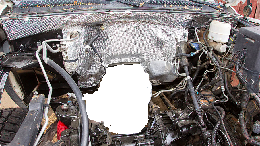
It should be less cluttered than this one since there doesn't need to be any exhaust, or fuel lines etc.. Because we no longer have an engine, we lost the vacuum pump for the brake booster, and the water pump for coolant flow. In addition we lost the belt drives for the air conditioner and power steering. We can compensate for these with electric versions.
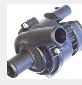 The water pump takes fluid from the radiator and pumps that to the cabin heating system and to the motor/inverter. The return lines run from these 2 systems back to the radiator.
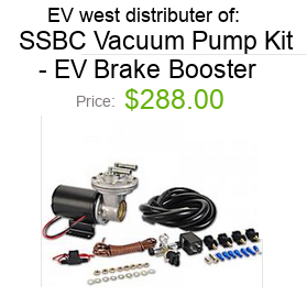 The brake system gets fed by this vacuum kit to restore complete brake opperation.
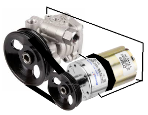 An electric motor connects by belts to two pumps that drive the power steering pump and A/C pumps (only power steering is shown). Up at the radiator we will need an electric fan.
 The electrical fuse panel contains a cable to the Digital Universal Dash computer, connections to pumps (water, steering, brakes, A/C), lighting inclusive of trailer plug assembly, Traction Inverter control wires.
For a Pick-up truck it is a judgement call to leave the compartment as is or enclose it for storage area. If enclosing it you need to care to provide a means of protecting drive belts from contact with stored objects and air pathway from the fan.
The electrical fuse panel contains a cable to the Digital Universal Dash computer, connections to pumps (water, steering, brakes, A/C), lighting inclusive of trailer plug assembly, Traction Inverter control wires.
For a Pick-up truck it is a judgement call to leave the compartment as is or enclose it for storage area. If enclosing it you need to care to provide a means of protecting drive belts from contact with stored objects and air pathway from the fan.

 For cars The FWD transaxle transmission needs removal and sent to have it changed from multi gear clutched gear to a single gear style.
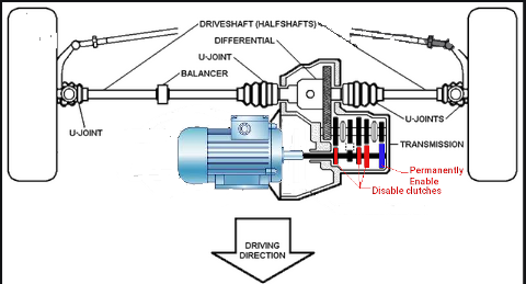
For vehicles which are not cars, a reasonably empty front canopy, we can turn our focus to the rear differential. On these vehicles we will shorten the drive shaft and place motor and gear box down close to the rear differential.
For cars The FWD transaxle transmission needs removal and sent to have it changed from multi gear clutched gear to a single gear style.
For vehicles which are not cars, a reasonably empty front canopy, we can turn our focus to the rear differential. On these vehicles we will shorten the drive shaft and place motor and gear box down close to the rear differential.
Shortened Drive shaft
This can be done either as a temporary shaft replacement or a permanent replacement but for best results you should visit a licensed drive shaft shop and have one made special. You will need in this case to measure the length needed, the yoke diameter and U-joint size.


 Mark a centered line length ways down the shaft. This line will be used to realign the shaft ends for re-welding together. It is important that the ends mate in the same balanced linear alignment after the section is removed. Do not cut too close to either end of the shaft.


 With the marks in place line the shaft absolutely level with-in the crop saw. Take care not to misshapen the shaft by tightening it too much. The shaft thickness is very thin walled.


 Cut, debur and polish the end being kept so a good strong weld can be made to rejoin ends. Repeat for the other end.


 Here we realign the ends and tac weld them temporary so we can check trueness. Welding will tend to slightly bend the shaft.

Using a point gauge rotate the shaft looking for as close to zero deviation as possible. only when 100% true can the shaft be welded permanently.
With the drive shaft out of the way and shortened, it is time add the motor and gear box such that they mount allowing the correct fit of the drive shaft.
For vehicles which are not cars, a reasonably empty front canopy, we can turn our focus to the rear differential. On these vehicles we will shorten the drive shaft and place motor and gear box down close to the rear differential.
Dash instrument cluster removal
There are so many models of every imaginable configuration so
here I will explain how the steps go for just one vehicle. For vehicles which are not cars, a reasonably empty front canopy, we can turn our focus to the rear differential. On these vehicles we will shorten the drive shaft and place motor and gear box down close to the rear differential.
tilt the steering wheel all the way down,
remove the shroud filler.
With the shroud removed. Now locate and remove the 4 collar
screws.
A stubby screw driver works best for accessing these as
there isn't much clearance from the column.
Now with a little perserverance work the collar out.
It
is suggested that you can't move the collar past the cover of the
steering column but with care it can be done.
Next have four screws to remove.
Tilt the instrument cluster down so you can access the plug
on the back. The plug has a dual lock system on it. First you must
push the red tab up towards the wires.
There are a push tab that must then be depressed so the
connector can be removed.
Now tilt and work the instrument
cluster out of the opening and this completes all the steps required
to prep the vehicle for conversion except for removal of wiring after
identifying what wires to keep, Removal of the old radio, old heating
control, and modifying the dash for the new system to be installed.
Chapter 04 Steel and Aluminum production facilities.
Fabrication facilities will be needed to make EV truck boxes out of steel and/or Aluminum, fabricate gearboxes for Motor to differencial connection, gears for transaxle transmission modifications, and protective Battery mount plates on Motorcoaches, and Motor mount plates.
I don't know who the so called experts are that were reported in the news but in my books they are probably dead wrong. We already fabricate cars for Ford, GM, and Chrysler all-be-it using alot of cross border trading. This book is about creation of new Industry in Canada focused on converting vehicles to EV. It does not have to stop there. With effort we can also make car, truck, buss, and motorhome chassis. The chassis would have suspension, steering, drive train, brakes imported from the UK, EU, Mexico, even Australia. Our metal Industry and Fiberglas industries could quite adequately make the cabins for the vehicles. It brings back what I was once told by an instructor back in grade school. You keep aiming for the stars, you will never reach them. Aim for the floor so you don't get discouraged. I ignored him and went with what my dad said. If you can think it, you can achieve it. If it hasn't been done it's because you haven't done it yet, and if it doesn't exist create it.
EV Pick-up Truck conversion
Lets look first at the Pick-up truck market. At 17% of all vehicles (5,780,000 vehicles), the new truck boxes house all the EV system except the in dash control center. Yes we can make modifications to the truck existing box but this is by far more labor intensive than just making the truck boxes custom.
In a very simple sense, a truck chassis comes in 3 types.
All 3 types have an engine compartment, passenger cabin, and frame where the load-box mounts.
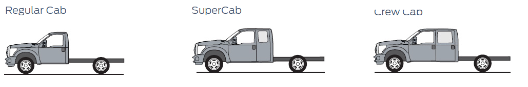 Without the box, the gas tank, and engine with all it’s associated systems, you have basically just passenger space, lights, steering, frame and brakes.
In my previous book on EV-Truck conversion I talked about fitting the batteries, motor and Inverter below the box and cab in frame space like the manufacturers of trucks suggest. The difficulties with this concept is moisture, vibration, impact from crash or road debris. Remember the pinto that exploded because the gas tank could be sandwiched in a crash?
Without the box, the gas tank, and engine with all it’s associated systems, you have basically just passenger space, lights, steering, frame and brakes.
In my previous book on EV-Truck conversion I talked about fitting the batteries, motor and Inverter below the box and cab in frame space like the manufacturers of trucks suggest. The difficulties with this concept is moisture, vibration, impact from crash or road debris. Remember the pinto that exploded because the gas tank could be sandwiched in a crash?
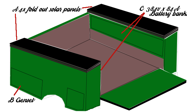 Seen here is the mock-up of a new truck box to be made. It has Solar panels that fold out for charging, Compartments either side for the Battery G-cells under that. Compartments either side ahead of the wheel wells for potentially a propane tank and Genset, and compartments either side behind the wheel wells for miscelanious storage. This truck bed would mount to the frame exactly like the former truck bed. During conversion, the Motor and inverter would mount under the bed and connect to the gearbox/differencial. Battery Gcells would be added to the provided compartments and Solar panels mounted to the box tops. The charge port and Electronics for charging and bank switching adds to the Battery compartment. Once this is complete there are just two cables (one for lights, one for control ) that pass between the box and the chassis.
Lithium ion Phosphate batteries are prone to bursting into flame if damaged by poor charging methods, or physical damage. As such, placing them under the cab between the frame rails leaves them vulnerable to road debris without a protective heavy plate. Servicing them is difficult as they are a mere 7 to 11 inches off the road. With the plate removed you then need to lower 500 lbs to 3600 lbs of battery down. In a crash or fire, passengers are directly above a potential inferno reaching 2000 °C in under 5 minutes! A safer and better solution is to move the batteries to the box upper sides above the wheel wells. Batteries are now encased in steel on 5 sides with a steel door for servicing. The batteries are safe from road debris, moisture, potential electrocution hazard and are away from occupants. In the enclosure the batteries can be strapped in place to avoid being bounced around.
For over 100 years, people have been exposing themselves to a known cancer causing agent that is a class 2 explosive. We are taking about gasoline and diesel fumes and the explosive liquid that gets vaporized and exploded 1000 times a minute just feet away. If the explosion in the engine manages to fracture the engine (and this happens many times a month) your only protection is a 1/16th inch thick Firewall!
In the event of a crash, the custom pick-up box if undamaged can be simply removed (6 bolts and 2 plug cables and one drive shaft) and transferred to a new chassis. Biggest part of expense salvaged.
EV Car conversion
Cars like the Malibu, Impala, Equinox, Volkswagons, Toyota, Honda, etc often place the gas tank under the rear seat. With Gcell technology as I would do it, we can remove the gas tank, build a strong steel battery box to accomodate the gcells such that rear seat is removed to open the battery storage and accomodate battery servicing and replacement. So once more we have need for the steel and aluminum fabrication.
EV Bus and motor coach conversion
Bus and motor coaches use class C Gcells which are largest size needed for the huge weight of these vehicles. The batteries in this case mount under the vehicle in space next to the frame. This requires Steel or Aluminum battery boxes to protect from road hazards.
Currently, Insurance companies deal with vehicles with fibreglass and plastic body as too expensive to repair and re-certify so they rate the value based upon mileage, age to govern write-off value. With metal construct they know they can be repaired so they try to fix until costs exceed the write-off value. But for EV they don’t understand electronics and batteries (which often comprise the underbelly) so even for minor repairs they write-off the vehicle. In essence a $33,000 vehicle looses $3,000 in value the minute it leaves the lot. ICE vehicles are rated for 300,000 miles or 8 years lifespan. If the vehicle is on a list of frequently stolen vehicles insurance policies are more expensive. If the vehicle is stolen or in an accident they use rating for an ICE even if it is an EV. The result is that a $68,000 EV truck in the eyes of Insurance is a $38,000 ICE truck equivalent. I am attempting to change this archaic behaviour.
Chapter 05 The Drive train suppliers
Drive train investigation
The end goal is to be able to move a 6400 lb mass on command. This relies upon the motor, gearbox, Inverter, and cooling technologies. We know that work creates heat. So if we expend energy to drive a motor fast, it will heat up because it is under load. Supplying that energy is an Inverter that changes Battery power measured in DC to alternating power called AC. The inverter therefore also will be working hard.
Ultimately we want to move 3 tonnes (6800lbs) from 0 to 120kph (0 to 72mph) and we would like to maintain this for 200kms (120miles). The laws of motion do not change just because we are driving the motion by a different method. So the distance traveled by the rotation of a 18" diameter tire will always be 3.14 (pi) x 18 (d) 56.61 inches until the tire wears down to it's minimum diameter of 17.70 inches which means it only travels 55.56 inches.
Mileage does not change either. There is 5280 feet in a mile and 12 inches to a foot. That's 63,360 inches to a mile. From this we can tell how many rotations of the tire are needed to cover the distance. (63,360 / 56.61)= 1119.23 r/m. The differential uses a ratio of how many turns of the drive shaft it takes per rotation of the tire. We need to know this ratio as it will tell us how fast the gearbox output shaft must spin to make 1 rotation. Multiply that by the number of rotations per mile and we have the first part of the equation.
From the above we now can work out rotations needed to go a specific distance and then work out the maximum time we want to take to make that distance. So if our differential is 5:1 then we know the drive shaft spins 5 times to turn the wheel 1 turn and 5 x 1119.23 = gearbox turns to go 1 mile = 5596.18 r/m. Rotations are counted in rounds per minute (rpm). There are 60 minutes to an hour. So if we want to go 1 mile per hour, we need to divide 5596.18 by 60 minutes to get the rpm. Which in this case is 93.26 rpm. To do the top speed of 72mph our gearbox will be rotating the driveshaft at 93.26 x 72 = 6715.42 rpm.
The preceding applies to a rear wheel drive but, and there is always a but, the vehicle may be FWD. It still has a differential as part of a transaxle to the cv axles. With FWD our CV axles mate with the differential gear inside the transmission. The differential gear mates with an output gear on a secondary shaft. The secondary shaft has 2 to 4 clutch gears. A clutch gear when unpressurized free spins. Force hydraulic pressure into the clutch and the outer gear transfers rotation into the inner gear on the output shaft.
A series of solenoids are used to redirect hydraulic fluid to the appropriate clutch gear. Only 1 clutch engages at a time. All the clutch gear outer gears mate with different size gears on the main shaft. In this manor, when a specific clutch engages, it's outer gear transfers the new ratio to the secondary shaft. The Main shaft mates with a flywheel clutch gear that when presurized transfers rotation from a torque converter to the main shaft. The torque converter mates with the engine output shaft. Part of the torque converter and Flywheel clutch has a hydraulic fluid pump that is used to pump the hydraulic fluid to the necessary components.
With RWD a gearbox mates between the motor and drive shaft. With FWD we need to modify the transaxle to a single fixed gear ratio. At top speed of 66mph, driveshaft rpm is 2907.5rpm. At local highway speeds here of 100kph to 110kph (60mph to 66mph) we need a motor that can sustain an rpm of 3000. Most motors run 500 to 3500rpm as upper limits with 1500 being a go to standard. This would mean we need a gear ratio of our gearbox to be 6:1 @ 500rpm and 2:1 @ 1500rpm and 1:1 @ 3000rpm. But from the source "electric cars are for girls" they say Most AC electric motors run 230v AC @ 60 Hz and a top speed of 1750rpm. They also say that to create 230V AC from a DC source you need 340V DC from your Battery pack. This matches with my experience too.
The Drive Inverter sits with the motor so it's three 2 gauge cables can adequately supply the motor. Under the chassis to the back we have a lighter 4 gauge cable to the charge port and batteries. The cables are overkill as far as run current goes. They are specific to handle the surge currents.
Our vehicle conversion replaces the engine with a motor & inverter.
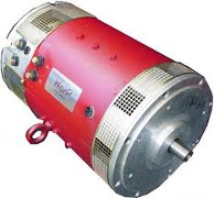
Motors
Three types of motor for EV's. We have the old low voltage type DC motor, The newer tech AC 3 phase, and the OEM AC 3 phase. All three can move the Car but each has it's own set of problems.
DC Motor
 Typically run from 12v lead acid cells, it is abundantly available, low in terms of cost, and great low end torque. At higher speeds, it has virtually no acceleration. It works fine at low speed short distances but can overheat easily under heavy load, higher speeds, or long distances. The controller is simple and governs just speed.
AC 3 phase Motor
 The go to solution for most EV conversions. Can attain higher speeds from higher voltages, Single gear ratio can do full range of motion with forward and reverse. handles higher loads with higher current packs, not near as bad heat generation, A more complex controller handles the speed and direction. Top end torque and passing power can be compensated for by the controller through a combination of voltage, frequency, and current. Motors are far lighter and smaller. Regenerative braking is possible. Few suppliers and larger costs.
AC 3 phase OEM Motor
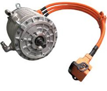 Hard to find except salvaged from wrecks, these are the goto for people that want to incorporate a custom solution into a similarly sized conversion. That is to say if you want to put a motor into a 3000 lb vehicle of roughly the same style as the motor from a wreck of a 3000 lb vehicle you can probably do it. The motors will be high voltage, high current, water or oil cooled, and have a special controller/inverter that checks, rotation, current draw, temperature, and other dynamics.
The one underlying thing that is emerging is that unlike ICE cars where demand for their engines is low, demand for the fuel left in the tank is non-existent, the electrics have high demand for motors, controllers, and Battery packs. This is because 1) they all are expensive, and 2) they last for years even decades. Being virtually a maintenance free system is quite different than their ICE counterpart which has thousands of moving wear prone parts.
The selection process
Many factors come into play in this process. Most focus on Speed, Acceleration, Distance, Charging, but those come after the computational work is done. For the motor, there are the factors of which type, how much voltage does it need, what is it's operational range (how many continuous rpms), how much current will it demand, what kind of load can it handle and for how long.
Then we have the drive coupling which can be gearbox, direct drive, transmission , and the coupling of the motor to the rear differential either directly or through a transmission/gearbox.
All this then has to be managed by the controller which must match the motor gearbox combo, and has certain demands it places on the required energy source (batteries).
TMG4 out of montreal canada only sells to municipalities and fully qualified OEM vehicle mechanical shops. Siemens has motors if you know the right specs for your need. Then I came across Motovario out of Italy that supplies markets all over the world and publish a huge build to order catalog explaining the specs mainly for their motors but applicable to motors in general from many sources.
From their catalog, I skipped past the first two sections of the first chapter defining the European regulation and conformity specs. If we were going into production instead of just trying to do a one off to prove the concept this would be more important. Here is the structure
of their motors:
 The motors can be flange mounted or base mounted or both. Design variations include high attitude applications, condensation remedies, forced cooling, and load stress due to vertical and horizontal mounting and / or direct drive or belt drive offsets to name a few.
The flange basically conforms to the diameter of the motor without the terminal block and base mounts. So the B5 flange type (no flange mounts) ranges from the smallest 120mm (4.724") to the largest 350mm (13.77"). The B14 flange (with mounts) ranges from the smallest 80mm (3.15") to the largest 200mm (7.87").
Chapter 06 Solar panel suppliers
This is the fourth solar system I am doing. The first was a 10 panel auto tilt system for the EV Motorhome, The coach system handled shore charging and solar panel alignment and charging. System 2 was for an EV-Tricycle and provided supplemental operating power for the batteries, range extension, charging. The panels in this case could be folded out of the way for access to a large storage basket. This time we will do a permanent vehicle charging array on a car, or Truck box with fold out panels or bus/coach. As with the motorhome system, charging will be 57v but due to less area for panels, will not have 20A charging. In our vehicle situation we are limited to 4A. In each case the cells claim 1 to 1.97 Amps per cell so when I say 4A system you could really get 7.88Amps in high sunlight.
Solar Charged
Solar charging is a method of charging Batteries using the power of the sun. While It can be designed to charge at any voltage, typically they are made for 48v systems and use a charge controller and can handle up to 4000 Ah given the right equipment. How effectively it charges is dependent on size of panels, number of panels, available sunlight and hours of sun exposure.
Applications are also wide ranging. There are small panels ideal for portable use to charge small electronics like cell phones, PDA's, iPads, and Laptops. Larger panels can be used on vehicles to either keep a full charge on a battery such as Lead-acid, Ni-Cad, or Lithium ion Phosphate. Going with even larger arrays of cells you can do more than just charge maintenance. The Larger arrays may even replace the need for shore power on RV's, or work as a back-up system on brick and mortar buildings.
The panels are made up of cells which are capable of producing 0.5v at 2A in good sunlight. The cells connect in series to make the voltage and panels connect in parallel to make the charge amps. The chart below assumes all Gcells are dead. In a normal sense you would charge as soon as you get to your destination. ! bank would be partially drained and the other would be full. If you had a range of 120 miles and used 15 miles, you have 1 full bank (60 miles) and one with 45 miles left. Over an 8 hour shift you could replenish 5 miles worth so your net use was just 10 miles and 3.5 hours at home restores the full pack from shore power. In all 3 renditions, the solar charge is a supplement to shore power charging. In the case of no shore power the solar system could be used. For those tied to Gas hogs or hybrid vehicles and even current fully electric vehicles, they don't have options if there is no charge station before their batteries die or fuel runs out.
| Charge Details |
| Unit type | Motorhome | E-Trike | truck |
| Kwatts | 110 | 1.5 | 64.5 |
| Panels | 10 | 2 | 2 |
| Volts | 60 | 30 | 60 |
| Amps nom | 20 | 4 | 4 |
| watts | 1200+ | 120 | 240 |
| Batteries | 16 | 2 | 16 |
| net watts | 75 | 60 | 15 |
| hours | 92 | 23 | 268.75 |
| Days | 9.2 | 2.3 | 26.88 |
Panel Planning
Solar charging on cars is really a dependant option. If the roof is soft top like a convertible or has luggage racks or sun roof there is no possible use. A car Solar panel would be about 3 feet by 3 feet
A truck box space is 13.5” x 8’ on either side. Like the trike panels can fold over each other when not in use. So charge surface is 54” x 8’. So maximum space for the solar array is 36 sq ft. This can accommodate 135x 4 inch by 2 inch polycrystaline solar cells per panel. We need to obtain 57v per panel which at 0.5v
per cell means we need each bank to be 114 series cells. There can be a total of 4 panels for a total of 4 Amps for a charging array of 228 Watts. These are the maximums for us to work with.
The solar panel factory would be called upon to make the 3 different types of vehicle panel and possibly even household panels.
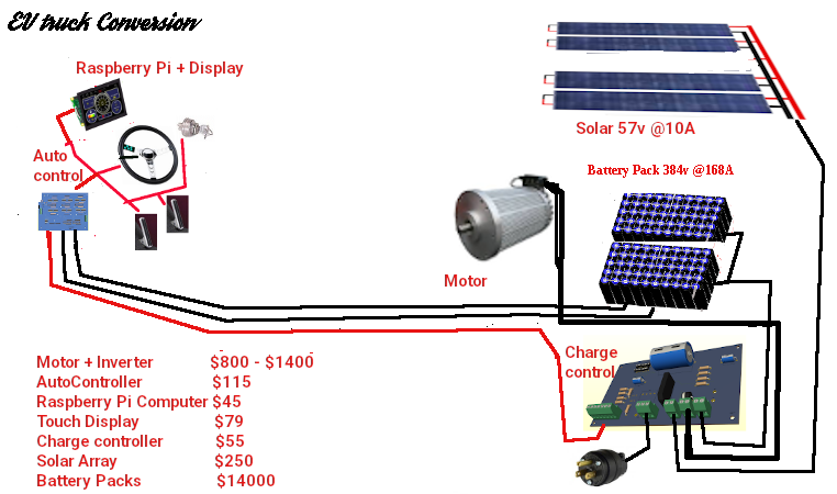 To the left is a Truck layout. For our Truck, the custom box contains the solar, battery banks, and the charge control. Under the custom box lies the motor and inverter. In the cab is the auto control, Dash computer and the steering, accelerate, and brakes.
This brings us to the last part of the plan. We must collect all the energy from the panels and get it down to the controller and subsequent battery banks. Point is that to minimize the wiring you want to have as few wires making a journey as possible. All our panels only connect in parallel so in the end only two wires make the journey to the controller. When the sun is poor or non-existant, a blocking diode in the controller prevents the battery from discharging through the panels which would destroy them.
Panels themselves, are made of either monocrystaline or polycrystaline cells. monocrystaline do so in a much smaller panel than the polycrystaline ones and are more expensive. The Panels themselves are fairly thin but mounted to a heavier structure or frame to give it strength in adverse weather. For optimum efficientcy you need to keep the panels clean from dirt and debris. Before moving on lets talk a bit about cost comparison. A monocrystaline cell can typically cost about $3.60ea and one site is offering 10 for $26. Comparing to polycrystaline the cost per cell is $0.13ea.
Now lets make it happen
Truck panel
Step 1: We need 1 box frames 87” x 13.5" made from 5/8ths 'U' channel and with a mounted plywood base 1/2" thick. On the plywood surfaces we need to mark out 2.125 x 4.125 squares into rows and columns observing there must be a 0.5" border around the edges and room at either end for wiring bussbars that we want to charge from a 57v solar.
With our charge delivery plan worked out and knowing the solar source voltage is to be 57v it is now a matter of cell arrangement to achieve the voltage and as high a current as space permits. Because our Gcells are 48v, we need 57v to accomplish charging. Polychrystline cells are 0.48v so 114 cells are needed in series. With 1/8th inch cell spacing, we need 253" or 21.08ft.
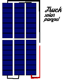 We can run 3 columns by 38 rows as shown. Each column of 38 cells wire in series with 0.125" spacing. Columns are also 0.125" spacing. Row 1,& 3 have (-) at the top, row 2 has (+) at the top. Row 1 (+) connects with row 2 (-), Row 2 (+) connects to row 3 (-). Row 3 (+) connects +57v @2A. Row 1 (-) is ground.
Bus or Coach panels
Step 1: We can make two box frames 21.75" x 54.125" or one frame 42.5" x 54.125" using 5/8" U-channel.
Step 2: 1/2" plywood back plate(s) cut to fit.
Step 3: On the plywood surfaces we need to mark out 2.125 x 4.125 squares into rows and columns observing there must be a 0.5" border around the edges and room at either end for wiring bussbars.
Step 4: Glue a 1/16" thick x 1/2" edge strip to go all the way around the plywood outer edges.
Step 5: Cut a 1/16" UV plexiglass lens to fit
That gives the idea behind the factory concept.
Chapter 07 Battery suppliers
Choice of cell types
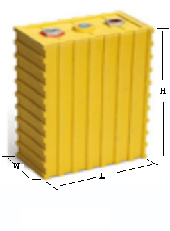
Batteries lie as the source of energy to power the EV. The type and configuration of the Batteries determine the potential of project design. Below are the specs for the five common lithium cell types. While all five can be combined to make the Banks or packs, the cell size and availability are the determining factors to project success.
In this chapter the term cell or battery refers to the individual cells like items 1,2,3 and 5. Gcells will refer to the 4th type below as a Gcell that is really a group of type 1,2,3 or 5 arranged into a single larger device. A Bank is a group of Gcells and a Pack is a group of Banks. In my design of battery packs I always have 2 interchangeable banks. The Gcells will be 48v for ease of charge and management. Three types of Gcell will fit needs of cars, trucks, and motor homes and busses.
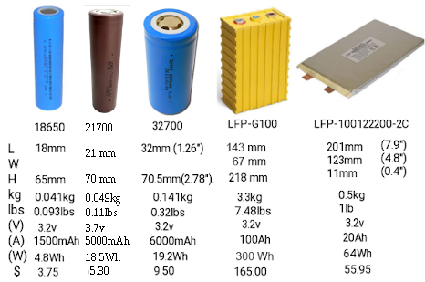 The 18650 was the original cell of choice for EV at 18mm x 65mm providing 800 to 1500mah. $5 to $12
The 21700 is the new choice at 21mm x 70mm with 5000mah $5.50 was $16
The 32700 was my preference 32mm x 70mm at 6000mah $9.50. Due to price drop the 21700 is the cheapest cost of the 4 and now results in smaller/lighter packs, when your talking about 1000’s of cells to make a pack the cost savings are significant. The 21700 type cell is half the price of the 32700 cell. It is also 1/3rd smaller diameter and 1/3rd the weight. This all means we can standardize packs to use replaceable Gcells rather than using huge packs.
The standard 12v lead acid battery is 7" x 9" x 12" full of acid and 85 lbs. Lithium ion phospate Gcells at 48v have no acid, and is in sizes of 6" x 10" x 10", 12" x 10" x 10" or 6" x 10" x 30" and weight of 40, 82, 117 lbs. Four times the voltage and close to the same size as lead-acid. Changing to 21700 type cells keeps the same rough sizes but reduces the weights and increases the Amps per battery.
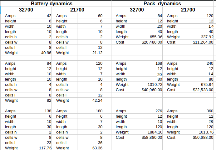 To run a 230v AC motor we need at least 340v DC from our pack. 8 series 48v Gcells per bank acheives this. The battery dynamics to the left shows the 48v types of Gcell. Looking at the pack dynamics we have 2 banks of 8 Gcells per bank. Eight Gcells in series makes 384v DC. Pack costs are greatly reduced and Amps increased with the 21700 type cells.
So we are going to run 384v made from 8 x 48v Gcells per bank with 2 banks to a pack. Vehicles under 5000 lbs will use to smallest Gcells, Vehicles at or over 5000 lbs but under 10,000 lbs will use the next larger Gcell type and Vehicles over 10,000 lbs will use the largest Gcell type. This addresses pack size and weight while also maximizing range.
Consider this:
To run a 230v AC motor we need at least 340v DC from our pack. 8 series 48v Gcells per bank acheives this. The battery dynamics to the left shows the 48v types of Gcell. Looking at the pack dynamics we have 2 banks of 8 Gcells per bank. Eight Gcells in series makes 384v DC. Pack costs are greatly reduced and Amps increased with the 21700 type cells.
So we are going to run 384v made from 8 x 48v Gcells per bank with 2 banks to a pack. Vehicles under 5000 lbs will use to smallest Gcells, Vehicles at or over 5000 lbs but under 10,000 lbs will use the next larger Gcell type and Vehicles over 10,000 lbs will use the largest Gcell type. This addresses pack size and weight while also maximizing range.
Consider this:
Before the big price drop on the 21700 cells, auto makers made one huge pack as part of the underbelly of the vehicle and due to weight and cell costs could not offer much in terms of range. Some like Toyota Prius went with a 100v AC motor which was double the weight and size of a 230v AC motor but allowed them to use a 144v DC pack for substancial weight savings. Here is what a 384v pack would be at consumer pricing. Auto makers can source in bulk at about 1/4th the costs.
- 18650 cells = (120 x 192) = 23,040 cells $276,480 2142 lbs
- 21700 cells = (120 x 58) = 6912 cells $110,592 691 lbs
- 32700 cells = (120 x 48) = 5760 cells $57,600 1843 lbs
Now with the price drop, the 288Ah pack takes on a much more reasonable cost factor but still is prohibitive due to weight for most vehicles.
- 18650 cells = (120 x 192) = 23,040 cells $276,480 2142 lbs
- 21700 cells = (120 x 58) = 6912 cells $34,560 691 lbs
- 32700 cells = (120 x 48) = 5760 cells $57,600 1843 lbs
Kilowatts is the determining factor with regards to range and weight of vehicle plays a big role. Volts * Amps = Watts and Watts / 1000 = KWatts. 384v * 288A = 110,592 watts / 1000 = 110.592 KW. The GVWR of the vehicle / 10000 = KW to go 1 mile. So if we are doing a small car with GVWR of 3000 lbs our range becomes 110.592/0.3= 368 miles to a charge. A truck at 6800 lbs would be 110.592/0.68= 162 miles and a large motor home at 17500 lbs becomes 110.592/1.75= 64.18 miles. If any of these vehicles are pulling a 14000 lb trailer the GCWR becomes 6800 lb truck + 14,000 lb trailer = 20,800 lbs and range becomes 53 miles. I am using maximum loads here. The Auto industry uses curb weight with 1 driver at 150 to 180 lbs which would say a car with curb weight of 2400 lbs + 150 lb driver = 110.592/0.255 = 417 miles.
Targeting the pack amps to be 120A, 240A, and 360A for 21700 Gcells affords us a fair range compromize with cars being 46.08/0.5= 92 miles, trucks at 92.16/0.68= 135 miles. and the motor home at 138.24/1.75= 78.99 miles. The average driver does about 33 miles a day and can do a slow recharge at home over a 6 hour period. The motor home having all the necessities of life carried with-in it may need help.
The Pick-up truck Pack
Factors to consider in converting a vehicle into an EV is really weight vs cost vs range in miles. For our Pick-up example we will remove:
- GVWR 6800 lbs
- GCWR 12000 lbs
- ICE related parts removal recovers 1760 lbs
- Custom box $1200 650 lbs
- Solar Array 116 lbs $200 228watts
- Class B 21700 type battery pack 16 replaceable 48v @ 120A 928 lbs $20,480
- KW= (384v*240A)/1000= 92.16 Maximum range 92.16/0.68= 135.5 miles
- Project Cost $25,380.00 + Labor (does not include gen-set `$500 and incidentals)
So when we convert a vehicle we are reducing curb weight by ~1760 lbs. Then we add back the motor, inverter, and digital control center 140 lbs. So we are ~1620 lbs lighter in curb weight at this point. The number of cells and cost per Pack is drastically reduced and still leaves us with-in the weight margin. That is why I chose to use 21700 cells for the off the shelf Gcell Batteries for all converted to EV vehicles. And if the auto manufactures would adopt this same concept all vehicles would be more friendly on the pocket book. With EV's from auto makers, you will have one huge pack, no solar charging, but hopefully user replaceable Gcells. With a converted vehicle, you get 2 banks to the pack (run on one while solar charging the other), and user replaceable Gcells.
Battery supply facilities
Our Battery supply facility will be tasked to build 48v Gcells in 3 class sizes. These batteries would be supplied to conversion centres and auto stores like canadian Tire and NAPA. There is potential with 10,000 conversions per day and home storage Gcells for Solar panels on homes. There is the potential of also creating a home solar panel industry or expanding existing ones.
Just like with lead acid where we turn in the battery for core charge so it can be rebuilt, the gcells can be rebuilt. Open the Gcell and extract the micro-cells (4 x 12v micro-cells) = 1 x 48v Gcell. Disassemble the micro-cells (tapping strips go for cycling), cells in good shape maybe reused, poor and bad cells go to final recovery. Gcells get rebuilt from new cells and new tapping wire. Reusable cells may go into games, laptops, flashlites etc where shorter lifespan is not so critical.
Because we have all cars, truck, suv’s using 12v systems and the 4 x 12v micro-cells make our Mini-packs (Gcells) we need to bring the 12v junction out as a 3rd terminal on each Gcell so it may be used in the first position of each bank.
To enclose such a Gcell you want it to be safe for operators, ventilated, short proof (conductivity safe), and reasonably light. To this end I propose we use the massive number of plastic bottle waste as they do in home construction just announced. The plastic bottle waste can make an excellant container.
The safest Packs are those with:
- Plastic or fiberglass structure so that people can be kept away from extreme energy supply..
- No Exposed High voltage or high current connections
- Metal re-enforced to withstand weight and also to protect from road hazards.
- Not too heavy to be managed.
- Easily mountable.
Making custom Gcells from cells
This design seems more feasible with 4 micro-cell blocks in an 10” x 10” x 6”. Add a 16 pin connector with pins 1 to 12 going to each (-) and pin 13 going to +48v and we have BMS ability.
1 bank would be 10” x 10” x 48”. I am doing the smallest Gcell in my explanations.
So it's time to look at the equipment you will most probably need to make battery packs.
And the supplies you will need to make battery Packs
Until you have all the equipment in place there is little need to start on the project.
The Spot welder is the first and most important thing needed to make battery packs. Heat from soldering irons can damage the batteries fast so avoid doing that!
Make a simple battery pack using the 21700 cells.
 You have some up front decisions to make about the pack you are about to make.
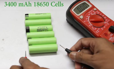
Fully charge all batteries and let them rest for a least 5 minutes then measure them so that you make sure each row has identical voltage. Ideally you also need to chart internal
resistance and here is how.
Internal resistance
Make a spreadsheet for your cells. For each cell measure the open voltage and record it. Pick a resistor and record it's read value. Put the resistor across the cell ends and measure the voltage across the known resistance. Record this next to the battery it refers to. V=IR so I=V/R. With the now known voltage across the resistor and known resistance we can calculate I. And knowing I, we can use (Vopen -Vload) / I = Rinternal. So for each cell record the Rinternal. Any cell with a high internal resistance will not work well in a Gcell. Are you sure you can trust a Gcell was tested properly and balanced properly before you got it?
Before you begin making the packs it is important to closely measure the voltage of each cell and group them such that all cells per Gcell read the same. All cells in a parallel bank will gravitate towards the weakest cell's voltage. This makes it difficult for the
BMS to level out the batteries consistently. You also need to verify the internal resistance of all cells to be in a parallel branch. This is done by measuring a resistor accurately and record it's resistance. Then place the resistor across the cell terminals and measure the voltage with the resistor added. Subtract the voltage with resistor from the open circuit voltage to get the voltage drop. Compute open voltage /Resistance (R) to get current (I). Calculate
Internal resistance as Voltage drop x I . Any cells with far out of line internal resistance should be allocated to some other project not critical.
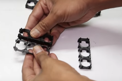
 Build your forms to accommodate the Gcell arrangement. In our case for a 10” x 10” x 6” Gcell we can go with 8 cells x 7 cells x 2 forms and 7 cells x 7 cells x 2 forms. For 32700 cells the forms are 1x2 or 1x3 but for 18650 the forms are 1x2 1x3 1x4 1x5 and even more types. If we connect 2) 1x3 and 1) 1x2 end to end and do 7 rows of that we have 1 form made. We repeat form 2, then connect 2) 1x2 and 1) 1x3 end to end and 7 rows of that we have form 3 made and repeat for form 4. Observe polarities ! All 7 columns in a row must be all (+) down or all (+) up. Row 1,3, 6, 8 should be (-) down, with Row 2, 4, 5, 7 being (+) down.

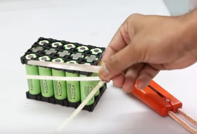
Once all cells are in place secure the top frame. We now need to cut tapping strips in Preparation to wire the cells. Remember these cells
are fully charged.
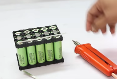

We will connect all (+) in each row together (Parallel) and connect short Tapping strips between (+) and next rows (-). Row 1 (-) also gets all 7 columns connected. Each (-) row gets a Tapping strip with a wire on for the BMS and row 1 (-) get heavy wire to (-) terminal, Row 5 (-) gets heavy wire to (+12v), Row 8 (+) goes heavy wire to Row 9 (-), and row 15 (+) goes heavy wire to +48v
 This example shows (+) row with all columns connected in parallel and in series with next row. In this example row 1 (-) is (- pole), row 1 (+) has (+3.2v) . Row 2 (+) connect all (+) together and all (+) wire to row 3(-). And row 3 (+) all connect together and a wire to (+9.6v)
as this is a 9.6v Gcell with a 3,2v tap.
This example shows (+) row with all columns connected in parallel and in series with next row. In this example row 1 (-) is (- pole), row 1 (+) has (+3.2v) . Row 2 (+) connect all (+) together and all (+) wire to row 3(-). And row 3 (+) all connect together and a wire to (+9.6v)
as this is a 9.6v Gcell with a 3,2v tap.
Chapter 08 Universal Dash computer Electronics
The vehicle will retain almost none of the electrical systems it once had. We will keep the wiring to the lights but install new lower powered LED lights. Keep the fuse box but repurpose it. Keep the stearing column and all it's controls. The existing system is basically the inertia switch main contactor, the brake, e-brake pedals and the new system (inside the brown borders).
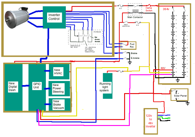 So moving left to right top to bottom we have:
- *New Drive Motor, Drive Inverter,Accelerator Pedal ***it replaces the gas ICE engine and all that went with it.
- Main contactor & inertia switch, Driver control, *New Fwd/rev switch, Brake pedals ***adding a FWD/REV switch.
- *New 16x 48v blocks making 2x banks at 384v, ***replaces the Gas fuel tank.
- *New 48v, 12v taps, *New 57v Charger, *New 480 watt 57v 4A Solar array or better
- *New Dash Display, computer, GPIO, HVAC, Pwr Steer, Brake vacuum ***Cockpit control system & implements replacement systems for HVAC, Steering, Brake vacuum.
- Running lights ***Kept as is.
- 120v Shore charger.
Wiring and feature pre planning
The concept here is to have an all purpose universal automotive controller and computer that can accommodate all vehicle classes from the sub-compact to the large scenic cruiser buses and Motor homes. To accomplish this the dash display has a credit card sized computer on it's back and this computer wires to a base board just behind it. The function of the base board is to supply power to the function boards, pass information to and from the computer to the various function boards, link the radio, GPS and phone into the system, and establish charge/discharge monitoring. Above the base board is 3 output modules, 2 input modules, and one analog module.
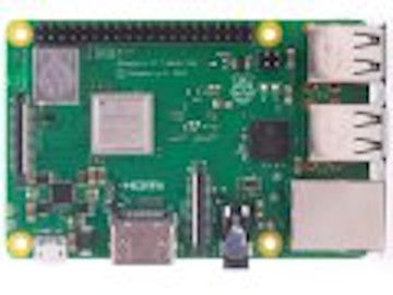
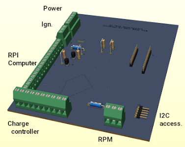
There are 3 output modules that are at addresses 0x20,0x21,and 0x22. There are 2 x 8bit channels per module. 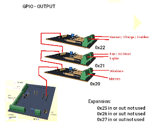
There are 2 input modules that are at addresses 0x23,0x24. There are 2 x 8bit channels per module. 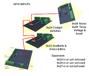
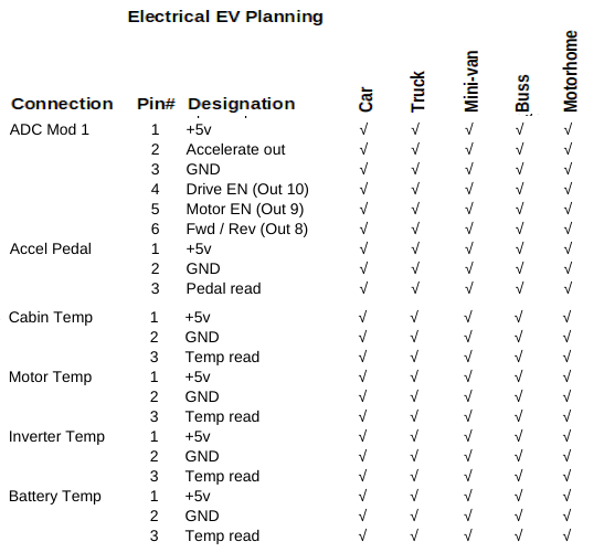 The final module is the ADC module with reads the accelerator pedal, the battery voltage and the temps on one side and controls the motor Inverter on the other side.
Canopy Systems
The cooling, steering, braking systems and lighting management resides up front in the canopy along with the Motor and Inverter control. As designed, we have Motor Control (Drive-En, Motor-En, RPM value) coming from the ADC board. We also monitor Inverter and Motor temp from the ADC board. We can control the Rad fan and Rad bypass using GPIO-2 outputs and can also heat the Inverter and Motor using GPIO-3 outputs. The base PCB collects rpm ticks from the sensor on the motor shaft.
GPIO-2 supplies Left-turn, Right-turn, Markers, headlight, Hi-Beam, and Fog lights. These signals are designed to operate 48v 0.02A LED light systems. If the plan is to use 12v incadencent bulbs, 10A relays will be needed. The steering pump, brake vacuum pump and water pump must connect to 12v using Drive-En signal so that operation is on when intending to move the vehicle. The headlight and high beam must use a relay. If motorhome application, the leveler output also needs a relay for the leveler pump. The Brake lights and reverse lights and trailer lights, while not part of the canopy systems will be in the canopy. We added an output to the above specs for sending signals to turn on and off brake lights and reverse lights. In an ICE design water pump, brake vacuum, and pwr steering are the result of the Engine running and in our case will be the result of Drive-En signal since the motor only turns when moving.
Cockpit Systems
In the cockpit with the driver will be the brake (and switch), E-Brake (and switch), Key switch, a Forward / Reverse switch, and the Potbox (accelerator). None of the high Voltage or High current comes into the vehicle. The dash computer monitors everything. The ignition is locked to on even if the key is removed. If an incorrect password is entered 3 times the computer will issue a shutdown. If the vehicle is in park and the operator selects shutdown it will also shutdown. We need to lock the ignition on until the computer says it's ok to turn off the system. At back we have charge control and Batteries and on the roof the solar arrays. Here to we need more signals. To charge the 48v battery blocks we have a Charge-En but now also need 8x48v blocks in series for 384v and in parallel to charge them. We can do this with a switcher board.
Items not yet incorporated in the design include keyless entry, cylon eye and electric door locks. Keyless entry and door locks will not be incorporated. Keyless entry needs the computer to be on 24/7 which is a power drain. Adding door locks requires an additional 2 to 4 signals. The cylon roaming eye is a novelty add-on. An anti-theft security system also would need to be an independant Add-on since we don't want to drain our batteries needlessly.
In an ICE the PCM (power control module) runs from the 12v battery 24/7 and typically draws 0.2 to 0.5 amps continuously. This has been a problem for years as a 65Ah battery with this constant drain can be depleted in as little as 130 hours of not being started. The PCM handles locking doors, unlocking doors, keyless entry, courtesy lights, and security systems. Being an EV we also have a problem since we can't start the vehicle to recharge the battery we would need to charge from solar or some land based power outlet.
Have we become too lazy, too paranoid, too dependent on automation for our own good. A friend bought a new Equinox (gas model) with power door locks, push button start, keyless entry, power windows, power seats, remote start, auto tow braking. Long story short, the car worked fine if started at least every 2 days. Place the car in neutral and hook it as a tow behind with dash on. Travel some 400 miles and go to start the vehicle. Oops!, doors don’t unlock, so he uses the emergency key entry to get inside. Wow dash has no power! He opens the hood and adds a boost battery. Ok, now he gets the vehicle to start, restores all the lost settings and ponders why this happens. The problem is bad automation that is evident on every new car on the market. In his case, he had to leave the dash active (on) but car in neutral so it could be towed, and so the car motion sensor could apply brakes when the towing vehicle applied brakes. Without the engine running there was no alternator to keep the battery charged. After about 300 miles the car battery was dead,
auto braking failed. So as he travels his 4000 mile bi-yearly trips he needs to stop and start the car and let it idle for 1/2 hour every 250 miles.
I ask, are automotive engineers so lame or behind the times that they don't know about the power wheelchair used for at least 50 years? A power wheelchair is very hard to push unless you pull the two freewheel levers. There is no need for power if pushed manually. So vehicles to be towed can have a similar system that doesn’t need power
to be on in order to tow them. In an automobile a simple lever rigged to the trans-axle output or drive shaft would make all vehicles towable with no need for power. For braking, the trailer light system turns on brake lights as needed and an inertia slide can regulate
how much power to apply to an electric brake booster. The power in this case comes from the 12v trailer charge wire supplied by the tow vehicle. Power door locks, remote start, vehicle location horn are unnecessary while towing as are power seats, power windows, gps, radio, so when the trailer cable attaches the PCM need not have power. We have the technology to store such settings in memory for when power is restored. The push button start/stop really does not need to be on 24/7/365 either. It works if the key fob is with-in range as a novelty. An on/off switch can power the PCM to monitor the key-fob to enable push button start/stop
To split or not to split
When it comes to high voltage
battery there becomes a very difficult problem. We have 15 cells in series and 7 cells in parallel to make 48v. The BMS needs to monitor each series cell row to balance them. Then we take these 48v gcell blocks and connect them in series to create the 384v bank and then connect two identical banks to make the 384v pack. Our most economical charge source is 57v such that we can charge direct from solar and / or convert 120v AC to 57v DC and charge from a shore line. Converting 57v to 420v DC to charge a 384v DC pack is extremely expensive and quite loss prone. Manually disconnecting 48v blocks so they can be charged individually is time consuming and potentially hazardous. So I needed another approach. the 48v blocks are in series during vehicle run operation but, and there is always a but, what if we electronically convert the series blocks into parallel to charge them.
Enter the MOSFET it can handle high currents and can be switched on or off with a low voltage signal.
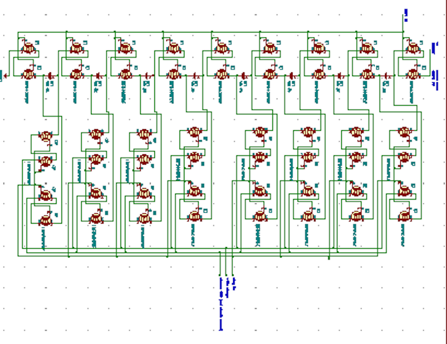 High power mosfets like the irf540 N-channel can handle the high voltage and current in the arrangement but, and there is always a but, it take 2 mosfets to replicate the triac due to properties of the diode body of the mosfet. The layout above is using the mosfets. Two
mosfets are used between each battery block and between the first and last battery block and the +384v and traction ground. So we have 18 Mosfets. Then there comes connecting the (+) and (-) of each battery block to the charger. The mosfet uses 4 per battery block. This description is for only one bank. We need to do this on both banks.
High power mosfets like the irf540 N-channel can handle the high voltage and current in the arrangement but, and there is always a but, it take 2 mosfets to replicate the triac due to properties of the diode body of the mosfet. The layout above is using the mosfets. Two
mosfets are used between each battery block and between the first and last battery block and the +384v and traction ground. So we have 18 Mosfets. Then there comes connecting the (+) and (-) of each battery block to the charger. The mosfet uses 4 per battery block. This description is for only one bank. We need to do this on both banks.
So we have 48 mosfets per bank. To save us from a PCB size nightmare and wiring nightmare, we can connect 6 Mosfets to each 48v block along with the BMS so that now we have 16 wires confined with-in each block for BMS and a simple (+) and (-) (En) (Chrge) (chrg+) (chrg-) passing from block to block. Special note: During RUN system
ground = Run ground and charge ground is disconnected. During charge, system ground = first 48v block ground, Run ground is disconnected and charge ground connects to all block (-).
Since the topic of high currents of the battery packs has been mentioned often, we need to address it. Lets say our Battery source is 384v @ 288A like we have. From the research on handling high voltage and current they make a very valid point. It is highly dangerous to have a power source over 100A continuous and in many jurisdictions it is even criminal. Most people own a car of some sort. It has a battery that is usually 65Ah or higher and this battery also has another rating 800 to 1500 CCA which refers to cold cranking Amps. Since the CCA is used only during the starting, it is deemed non-continuous and safe. Our 288A pack follows the same guideline. During the first half cycle 1/120th of a second at motor start it draws 200A but then draws beteen 0 and 10A depending on load and speed. It's kinda like if we directed all water from Niagra falls into your shower at home. Use of the whole all at once would drown you but using a tricle is enough and great.
The DIY sites abound and talk of 600A to 1000A systems. They are talking about the current used over the whole range to travel not the typical current draw at a moment in time. If it were over a moment in time the maximum range would be maybe 2 miles. It is over the whole range. so if you have 56 mile range, and it uses 560A to do that range, you are using 10A per mile. and if you are doing 60mph then you are using 10A per minute.
 Here is a switching circuit on the left and a bms circuit on the right which we don’t need right now in the discussion. We would attach a switching circuit to each 48v Gcell and control all the charge and all the run leads together so a charge enable switches all Gcells to be in parallel and a run enable switches them back to series.

Chapter 09 The Conversion centres
Just as the disassembly centers would be spread over the many provinces and teritories, the same is true for the conversion shops. The conversion shops can be independant or combined with disassembly shops in production line manor. Both type of shop require vehicle inspectors to assure compliance with insurance and transport Canada rules.
The basic EV
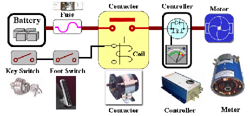 The diagram here is over simplified. It works as a working model for operation of an EV. If you used this model, yes you would have electric drive but at full speed all the time and once you are out of power everything stops. So we need to enhance the
drawing.
The diagram here is over simplified. It works as a working model for operation of an EV. If you used this model, yes you would have electric drive but at full speed all the time and once you are out of power everything stops. So we need to enhance the
drawing.
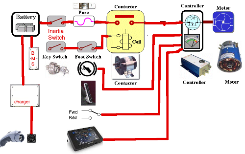 You notice it is basically the same with the missing components now shown. The Inertia Switch stops everything in the event of an accident, The BMS protects the batteries from over charge and over draw, The re-charger and port to restore the batteries, Accelerator part of the pedal to regulate speed, the dash to monitor speed and results, and the forward and reverse switch to choose direction of travel.
Additional to these systems, are the automotive systems for lights, braking, a/c, radio, cooling and steering. All of which are not shown on this depiction.
Ideally there should be cutoff switches between the battery banks
The contactor
This a
High voltage High current solenoid. It is controlled through a low
voltage side operated by the key switch/foot switch. When you
press slightly on the accelerator, the switch engages and if the
key is on, power flows to the controller through the contactor.
Inertia switch
Is a high
current high voltage device that cuts power under abrupt impact.
It must be reset for power to resume.
Main Fuse
Has to be
rated for the maximum Voltage and current and is designed to blow
if limits are exceeded.
Key Switch
Is the master on/off of the car.
Foot Switch Accelerator
Your
dynamic speed control. The switch part enables the contactor to
supply power and the Accelerator part says how much power to
supply.
The Charge Port
This has both the supply lines to the
charger an interlock switch to tell the charger external charge is
securely attached. It is possible for there to be 2 or three
charge connections depending upon design. You could have 230V AC
@50A, 120 @ 30A AC, 115v @ 15A AC even some like 460V 600A.
|
|
Dash Display
Of coarse
you want a fancy dash display that tells you how much charge you
have, estimated distance left, Pack condition, Speed and for the
hot rod types, your rpm/1000. That last item is no longer required
as you aren't needing to know at what rev you need to shift.
Manual transmissions are not found anymore in main stream life and
EV's don't even have one most of the time.
Controller
Ah! the heart and brains of this
outfit. The controller also known as the Inverter, after the
function that it does. In the realm of DC motors these do not
exist. But for AC motors they are the most necessary part. Types
range from the very trivial control to highly sophisticated ones.
Basically, they take an input voltage range to produce an AC
output range of voltage. Voltage controls the speed, well kinda.
In a flat inverter it controls the speed, but in a structured
inverter, changing the output frequency can also be used to
increase the speed. Current from the pack of batteries provides
the torque drive.
Depending on
the motor chosen for a given project, it may already come with a
matching controller. You can use the supplied controller if one is
given, or can also design and build your own. Most OEM's build
their own to their exacting specifications. But the design of such
is a monumental task involving IGBT's to control high voltages and
currents, fast switching and sensing devices and the like.
|
|
|
|
BMS
Essential to the health of the batteries is the Batteries Management System. It's job is to identify cells that are not as charged as others and balance things. It looks at temperature, State of charge, amount of charge or
discharge in an effort to keep all cells in prime condition.
Charger
There are a wide range chargers and charger designs. The charger must optimize the input power (AC) into (DC) known as rectifying it. Then charging the batteries from this rectified output. A good charging system will not allow the batteries
to be over charged and will in fact shut off when they reach full charge. With Lithium Phosphate, you can not drain them more than 80% and can not charge more than 95%. To do so would damage the cells. Also take care considering fast charging. Charging at 4.2v per cell
is typical of BMS monitored and controlled systems but, and there is always a but, 4.2v will degrade the cells life. A smart choice is to charge at a maximum of 4v which can extend a cells life by more than 25%. Current actually does the charging. If cells are rated for 1A or
6A for example they should not ever be charged faster than that. This is known as the batteries 1C rating. fast charging charges at 2C, 3C, 4C. Some liFePo4 cells can tolerate 2C but not all. Even fewer can tolerate 3C and none can tolerate 4C.
So consider this, you have a Pack that is 8 Gcells in series so you have 384v and your pack current is 600A and you are going to charge from an AC home outlet. So you have 120v @ 15A. You have an ideal Inverter charger that is very efficient and @ 384v has 5A for charging. This will do great and charge the pack over the next 5 days. Each cell is happy because it gets 0.2 amps slow charge. But you get to a fast charge station 480v 300A fast charge and give it a wirl. The on board inverter converts 480v to 384v and gives it to the batteries. The battery packs are very angry with you. If the individual cells
are 18650 they can handle 1 maybe 1.5A if they are 1.1A cells you are charging at 3C. if they 1.5A cells you are at 2C. If they are 32700 cells they are ok because they can deal with 6A.
The PWM Pure Sine Drive Inverter
The Pure sine wave inversion on the surface does a clean AC wave output to the motor. It gets it's cue from the Accelerator Potbox as to what the demanded speed of rotation is to be. It then needs to read the direction switch (FWD/REV) and use this to determine the frequency to deliver to the AC motor. IF 60Hz is the full on normal run speed of the motor at say 3500rpm, and you are asking for 200rpm then the pulse given to the motor 17% of 60 cycle per second. if I did the math right the pulse would have been .17 seconds.
Installing the New systems
My proto-type dash unit is 10”x8”x6” with a 10” display on
it’s face. While mine used descrete components a production model
would use smt’s to reduce size to 10”x8”x4”. Other
possibilities for the Universal dash would be a 7” display
5.5”x4”x4”, or a 4.3” display 3”x4”x4”
 The units are self contained such that they can be removed and fully tested with a PC or left in place and tested in the vehicle. There are no cryptic numeric codes like the ICE vehicles have. All inputs and outputs can be tested on screen. Each unit contains 1 computer, 2 input modules, 3 output modules, 1 ADC module, 1 radio, 1 amplifier, 1 gps, 1 dashcam, 1 mother board. Depending on the size of the instrument cluster of the vehicle will determine which display would be best. You should want to limit modifications to the dash as much as possible. The existing radio, heating control and info center will likely not be needed.
Working on HVAC
 For heating and cooling, we will pass the Radiator Water outlet line to a
12v pump and 2 electric valves. If the Motor, Inverters, and Batteries are too hot, the associated valve opens and the fan engages to cycle the solution through the Radiator for cooling. In the cabin,
I guess I could have routed a take off from the radiator to pass through the inside heating vents but chose instead to use a two speed fan and a choice of heat on through ceramic heater, or AC on through
a 12v compressor of refrigerant.
For heating and cooling, we will pass the Radiator Water outlet line to a
12v pump and 2 electric valves. If the Motor, Inverters, and Batteries are too hot, the associated valve opens and the fan engages to cycle the solution through the Radiator for cooling. In the cabin,
I guess I could have routed a take off from the radiator to pass through the inside heating vents but chose instead to use a two speed fan and a choice of heat on through ceramic heater, or AC on through
a 12v compressor of refrigerant.
As seen here, While the motor, Inverter, batteries are below 50
degrees
F, the radiator fan is off, the bypass value is bypassing the radiator and the coolant pump is off. Once temps rise to above 50 degrees F the pump comes on and when temps climb above 170 degree F
the valve opens to redirect full coolant flow through the radiator and the fan engages.
It's important that the Batteries and Inverter remain in the operational range during Driving and charging so if they are too cold an auxiliary ceramic heater and fan comes on to raise the temperature, If too hot the fan comes on to cool them.
The new Cockpit:
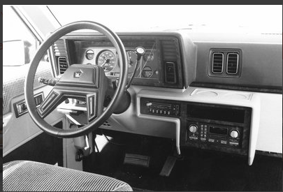 becomes ...

The mock-up picture at the top of the page gives the basic idea. With a digital dash, a touch display that is easier to see replaces the mundain grey on grey instrument cluster. The center section is removed as the radio and heating/cooling is handled electronically. Essentially, the entire Dash instrument cluster can be run and tested as a self contained system. We will replace the accelerator with a pot-box foot operated potentiometer, and we leave the brake pedal and E-Brake pedals as is. We lose hundreds of wires to give a nice clean and clear compartment. So for starters we will build the Dash instrument cluster as follows:
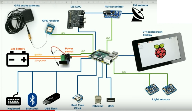
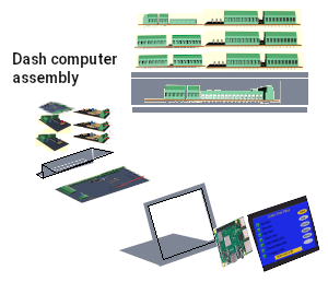
Digital Dash
We want to make a New Digital Dash for a vehicle. So what sort of things should this Dash have. For ease of viewing it should have at least a 10" HDMI displays and full computer control. Obviously it needs to have adjustable brightness for bright daylight and dark night driving. Being 10" displays they will be 8" wide and 6" tall and sit back from the driver. It should control most if not all driving seat adjustments, so it needs Radio control with volume, station, and balance, Heating and A/C adjustment, Mirror adjustment, Pre driving system checks, Back-up camera with rear view capability, possibly a front view dash cam, and be fully Electric Vehicle capable. Optional would be GPS navigation, Bluetooth connectivity for hands free phone use. That's a pretty tall order but lets see what we can do.
Choosing to have full computer control is most likely to use a Raspberry Pi 3b+ as it has a lot of functionality and is small (credit card sized). A USB mini keyboard gives us the ability to make direct system changes should the need arise. Our Pi computer would mount to the back of the display and light sensors mounted into the frame surrounding the displays would give us the ability to control display brightness automatically. Forward facing dash cam is no problem as it can mount to the back and plug conveniently into Raspberry Pi.
I2C is a two wire communication protocol that can access and control roughly 128 devices with many of them handling many different functions. So as not to overload the storage capabilities of the Pi, we will use an external usb harddrive for all footage from webcam and Back-up/rear view camera's. Now we will look at how we can implement all the features by the PI computer.
Universal EV conversion
Lets take a look at it from an
operators standpoint. We need to know our speed and whether it is Kph or Mph. The old way was to have a cable from the transmission to the speedometer. The speedometer updated a mechanical odometer in Mph only. A moving needle rotated around to point to tiny numbers. Newer versions used a sensor and moving coil meter in much the same way. And the newest of vehicles have custom dash with speed readout and digital odometer.
Our dash display is a 10 inch touch screen. In the center is a speed readout with numbers around the perimeter. As speed increases the number background turns from Grey to green. two buttons below the speedo select Kph or Mph and automatically adjust the speed numbers and readout to match.
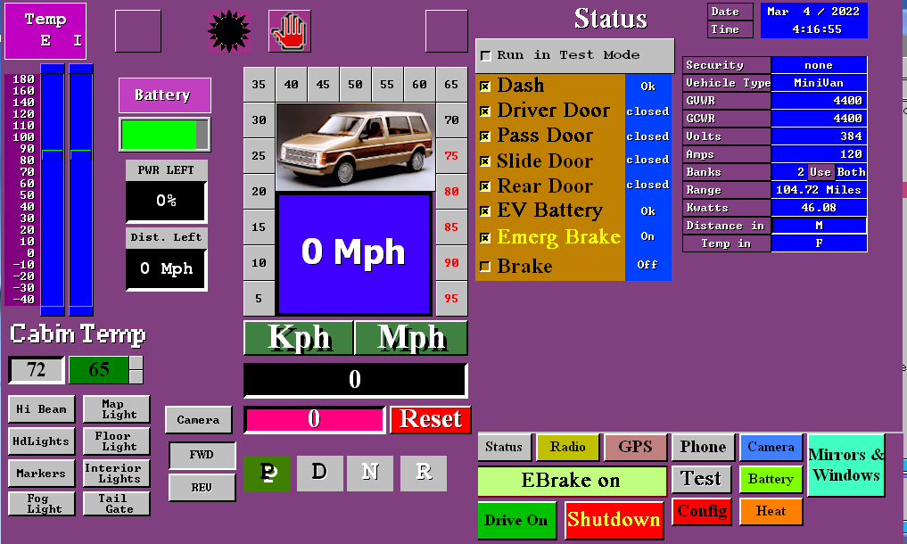 Above the speedo is left turn and right turn indicators and the current state of the headlights (on/off/hbeam) and whether cruise is on or off. A Trip odometer and trip reset is below the odometer. Being an electric Vehicle we don't use a gear shift in the usual manor. It's all Electronic. When Ebrake is ON you are in Park. When off you are in neutral. When stopped you can use a switch on the dash to select FWD/REV or the touch screen to switch from FWD or REV. Being an EV means we need to know the state of the Battery and the Inverter temps and Motor temps. Top left shows this. Under that is the current cabin temp and desired cabin temp. And below that we have buttons to control lights using the touch screen.
To the right is the main
menu. It allows you to select different features using the buttons at the bottom, Right now the status display is showing results of the system test. It verifies that it is OK to use the vehicle. One might ask why do we need to verify it is OK to use the vehicle. The answer is simple. The system checks that the dash control system is working, Seat belts are buckled, and the doors closed and eBrake applied before it will allow the motor to function. It is more informative than a check engine light and buzzers. Later you will see how it plays into doing self repairs. For now let's assume it all is OK and so we select Drive On.
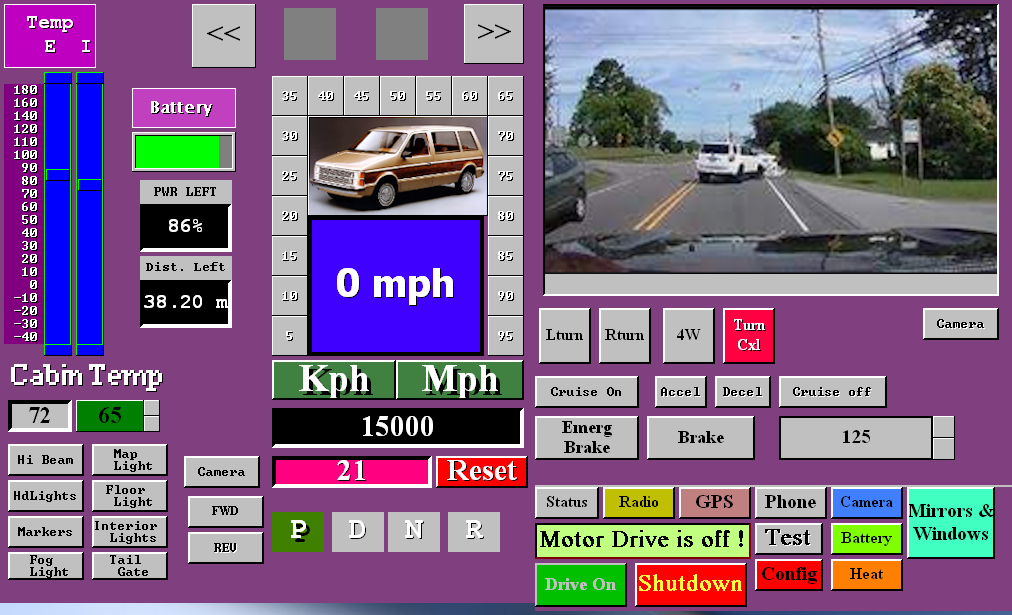 The right side changes to the drive screen. At the top is the Dash cam/Backup cam display. Using the Camera button below the display you can view the Dash cam/Backup cam/Info displays. There are also touch buttons to turn on or off Turn signals, Hazard flash, Brakes, and Cruise control. While you still have all these in the car, you may use either the car provided ones or the touch screen ones. In test mode, you can use the Accelerator at the bottom without actually operating the motor.
There is a Credit card sized computer on the back of the 10 inch Display. It costs an amazing $45 or less and is the heart and brains of the Vehicle. It takes automotive controls and user actions to control the whole vehicle through a simple single board controller I have designed. But more on that later.
Power first. We need a Battery system that has a certain voltage, specific Amp capacity, which based upon the formula V*A=W we can determine watts of the battery. Using the GVWR or GCWR we can determine the distance we can go. W/1000 = kw, and GVWR/10000 = kWh or kilowatts to move a weight per hour on flat even ground. For my Motor home it was 17500lbs/10000 = 1.75kwh per mile. A truck as above is 6800/10000=0.68kwh/m. To deal in KMs take 20*m/12=km.
So for the truck we have 2 banks of battery at 384v @120A = 46.08kw per bank. 2 * 46.08 = 92.16kw pack and so @ 0.68kwh/m range should be at least 135 miles. Normally you enable one bank for driving and when you reach 20% left the computer switches to the second bank and gives notice you are on the second bank. From the battery screen you can control which battery to use for driving and whish to be solar charged if any.
 Charge in and out of the battery is measured in coulombs. 3600coulombs = 1A. So the computer reads the amps per second going into the battery or out of the battery system. It can update in real time the amount of battery left and how much farther you can go. Solar panels over the wheel wells may charge the system when there is enough sunlight.
Not to fret, most people travel less than 50km in a day and if we go with figures used by the insurance bureaus to compute insurance, 20,000km/y = 54km/day = 33m/day = 40% use or 2.5 hours charge time needed per day.
For the battery screen we can use battery bank 1 or 2 or both for use in driving. If not using both, the non-enabled one can be solar charged while you drive. Enabling solar charge works if there is enough sunlight. And of course there is 120v AC charge when parked. Selecting shutdown when charging is complete only works on a parked vehicle so you can set to charge while your shopping or at work and the system will shutdown unattended. Ideally, you would disable both batteries for driving and choose Shutdown when complete which disables all vehicle operations during the charge cycle. The values shown on the screen actually come from the config screen. They change as conditions change.
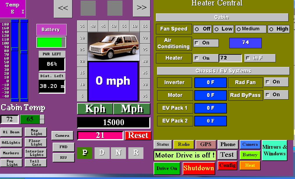 Next up is the heater control screen. It allows changing for comfort and checking on the health of systems.
Comfort wise you can set fan speed, AC on or off set your desired temperature and choose between degrees in C or F. You can view the temps in the battery packs, motor, inverter. In cold weather the EV systems need heat for optimum functionality until their self generated heat gets too hot then the cooling systems come on to cool them down until they reach minimum ideal temperature.
 Self explanatory here. You press a button to move the mirror to the desired state. Likewise you can open and close 4 different windows.
 Here is a computer control of a Navcon GPS system at the top is the selected road map with map adjustment below. Under that is where you state your starting address and ending address using the provided keys at the bottom. The map shows your start point and end point when your current position allows them to show. Your current position always shows center unless you slide the map using N E W S keys.
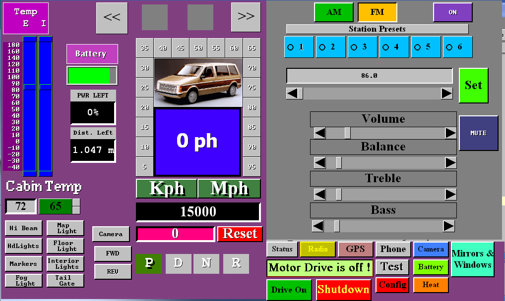
No presumption about there being a radio or not. Using a built in radio module and amplifier operated by this touch screen display, all you add is speakers which usually exist in any donor car being converted.
 Imagine if you will, on your current vehicle, you have a check engine light, battery/alternator light, temperature light and sometimes a little door open indicator. If something goes wrong you need to go to a garage and pay for them to use a OBDCII to read cryptic error codes and reset them after fixing the problem.
This EV Dash has built in TEST and Report facility. The report facility just tells what the current detected states are. The Test facility here allows you to see 10 categories on the left with currently the window up/down set showing. It is a work in progress as I refine software to match the actual electronics.
By turning on and off the checkboxes you can confirm that the desired action is being done like moving the mirror left or right or up or down. Turning on or off the park lights, headlights, or seeing that when you press on the brake pedal the automotive control boards sees it. You are having trouble with cruise coming on when you ask for it. So you come here select CTRL (control) and see if the cruise on indicator is on or off. Press Cruise on the steering wheel and see if it shows you pressed the button. If there was nothing happening, check the other cruise related buttons or turn signals or hazard and if they are all dead the cable is likely unplugged. If only one is not working it is likely a broken wire or bad switch.
 Then we have the camera screen to be used only when stopped. If you want to use it while driving, you can’t because that is a huge safety issue.
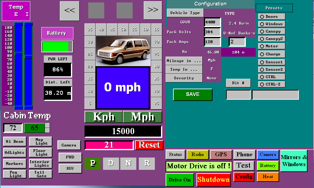 Two more screens are present but not yet functioning. One is the phone and the other is the Config screen. phone would connect to your phone by bluetouth and config allows all the presets to be set.
Electrical Systems
The electrical systems of an EV conversion encompass several interconnected things. At the helm is the computer controller which in this case is a Raspberry Pi 3b credit card sized computer. This computer connects by 16 wires to a base PCB. The base PCB also obtains power from the battery packs, and has connections for ignition switch, charge control, RPM tick sensor, I2C accessories, and the input, output, and ADC bits arrays. There is an on board I2C level shifter for comunication. The inputs and ADC bits are provided on a 11 pin header and the outputs on a 14 pin header. As such the first part of the system is the computer and the base distribution system.
 To the left is the base PCB. Below are the input and output modules that sit above the base.
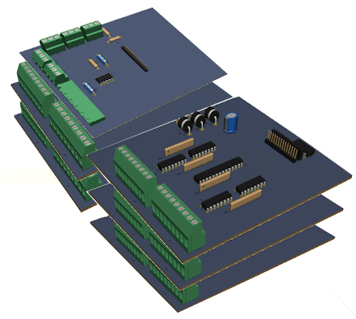 There are two input modules and the ADC module in the first stack and three output modules in the second stack. All connections to the modules are at the face edge to the automotive functions they go to. Two headers are on each of these boards. One goes to the previous board and one to the next. So base 11pin connects to input board 1. Input board 1 (second connector) goes to board 2. Board 2 (second connector) goes to ADC board. On the output boards they inter-connect in a similar fashion.
In such a manor, we can have the entire electronics distribution system in a box about 9" x 6" x 4.5". This makes up the second part of the system. In the engine canopy we have Motor, PWM Inverter, canopy controller, and sense passthrough. The Charge controller mounted at the back of the vehicle which manages 120 AC charge and Solar charge, and finally the batteries with BMS and switching charge control.
Raspberry Pi 3b computer
This tiny but powerful little
computer has 4 usb 2.0, I2C, SPI, RxTx comunication, Ethernet, a 40pin GPIO connection and HDMI is where we will be most concerned with.
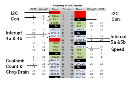
Because we added 2 banks of battery, we needed to add a second set of Coulomb Count & Chrg/Drain leaving just 5 GPIO unassigned. A front facing CCM camera connects to the CCM port to provide a dashcam and the rear backup camera talks by bluetooth.
The Raspberry Pi 3b 40 pin GPIO connector is a very powerful tool in my design. While not all the pins can be used and several are duplicates, there are 17 available and we are only using 7 to 9. The breakdown is as follows:
- 1,17 = +3.3v
- 2,4 = +5v
- 5,9,14,20,25,30,34,39 = GND
- 3,5,27,28 = I2C#1 &
I2C#2 we are using only I2C#1 @ 3,5
- 7,19,21,23,24,26 = SPI1 & SPI2
- 13,15 = int4a int4b
- 16,18 = int5a int5b
- 22 = rpm sense
- 29,31 = charge / discharge counting
- 8,10 = Rxd Txd
- 11,12,32,35,36,37,38,40 = GPIO unused
The RPI is powered by the Base PCB that is handling all
comunication to the various systems. I2C provides communication to the various systems with pins 13, 15, 16, 18, 22, 29 used as interupts for input changes (int4a int4b int5a int5b), rpm sense, and charge/discharge ticks. pin 31 tells the direction (+)=charge (-)=discharge. During programming the EV system the first of 4 USB ports attaches a keyboard. A second USB port is used for the back camera recording to a flashdrive. The HDMI attaches to the display and a 3rd USB provides touch screen functionality. The DashCam connects to the CCM camera connection. The rear camera is still being worked on.
Base module
Observing the images below, we can see the base top view, left edge view, and front edge view. Left side back is the power connection with GND, +3.2v, +6.4v, +12v, and +48v. Moving forward we have the ignition switch which turns on the whole system. Ideally the ignition once activated only turns off under computer control. If shut off before the vehicle is safe to shut down, it holds power on until given a shutdown command. Our next connection goes to the Raspberry Pi 3b computer. The last view has the charge controller connector and the RPM sense. Far right is the I2C carry on connector pointing off the right side. This connector is used to add GPS, Bluetooth, and AM/FM Radio to the system.

PCB prints and schematics are available in a separate service booklet.
GPIO - INPUT modules
The input modules have 16 inputs per module. The first module is at 0x23 and the second one is at 0x24. Each module has a single mcp23017 GPIO-expander chip, with selectable addressing. All connectors have pin 1 designated as the ground pin. The Input boards have a 4 pin connection on the side that provides GND, +5v, +12v, and +48v just in case the need arises. The first input module (0x23) handles seatbelts, doors, and bins. If a door or bin is open that input is grounded. If a seatbelt is unbuckled it is
also grounded.
The second input board connects to the steering wheel cruise control switches, the E-Brake switch, the Brake switch, the left turn, right turn, hazard switches on the column, hbeam, Fwd, Rev, headlight and marker light switches. The switches are actually repurposed to simply toggle between +5v (off) and Ground (on) to tell the computer what the operator has selected. The output board does the actual activating of the feature based upon user manual controls or touch screen selected operation.
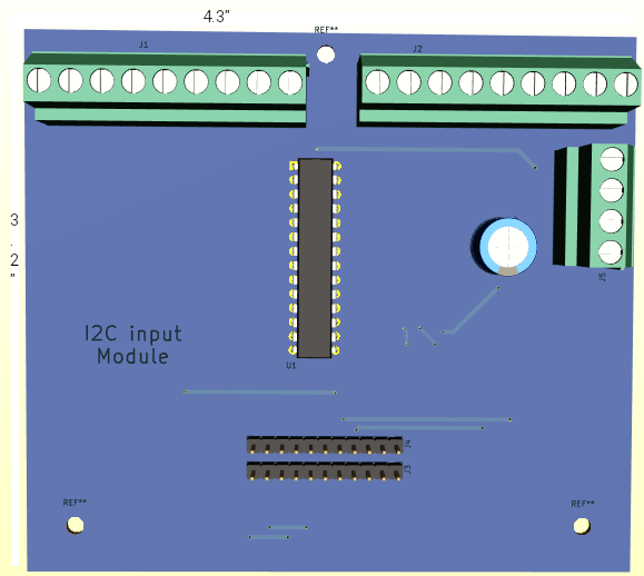
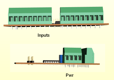
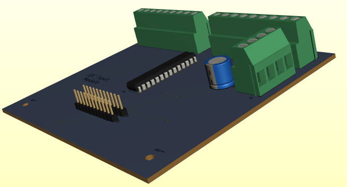
ADC module
The top board on the first stack handles ADC operations. These operations are handled by two IC's. Address 0x28 is the accelerator output to the Motor controller. and address 0x48 is the one that reads the Battery voltage level, Temperatures of the motor, the Inverter, the Batteries, and the cabin. It also reads the accelerator pedal. This gives the computer the means to have both manual and cruise control, and keep the operator informed of the temperatures, and charge state in real time.
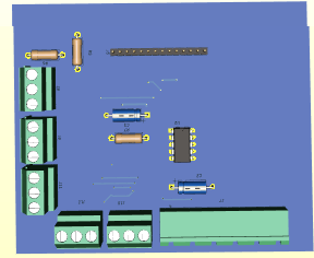
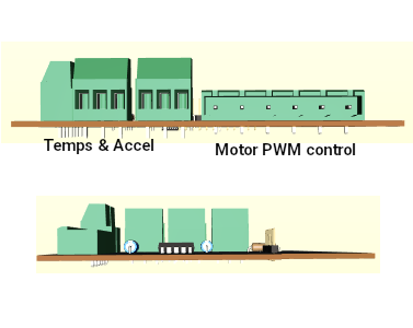
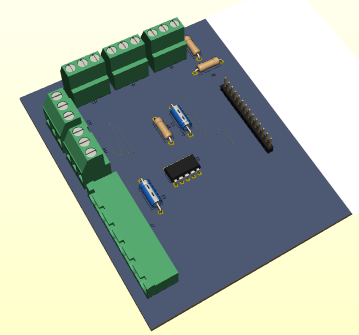
A DS3502 (0x28 address) 7bit digital potentiometer presents the desired speed value to the motor controller. This value is either the value obtained from the accelerator pedal reading or the value set when cruise is enabled. Let us say that 8000 rpm is full speed from the motor and results in 66mph. This potentiometer has 128 increments so when the value is 0 (the first increment), motor rpm = 0 and speed = 0mph. When the value increases to 1, rpm increases to 62.5rpm and speed = 0.51mph. This is of course governed by 3 factors provided by the computer. These factors are DriveEn which powers up the Invertor, MotorEn which allows the motor drive to function, and lastly Fwd/Rev which determines whether to move forward or reverse.
The ADS7830 8 channel Analog to digital converter, supplies the computer with the battery voltage in the range of 336v to 384v, 4 Temperatures in the range of -60 to 200 degrees F for Motor, Battery, Cabin, Inverter and the read accelerator value 0v to 5v. Each value is in 1024 increments such that battery voltage is in 0.375v increments, Temperatures are in 0.2539 degrees F, and accelerator is 0.00488v = 1/8th of 0.51mph per increment. The computer basically just divides the accelerator value by 8 such that any value below 0.039 = 0.
GPIO - Output modules
The output modules are far more complex than the input modules. While they still use the mcp23017 chip, with selectable address 0x20, 0x21, and 0x22, they also have optic isolators and pull-up resistors. The expander chips have limited ability to drive heavy loads so the isolators provide both heavy load capability and increased voltage to feature capability.
For example, the automotive
mirror up-down-left-right motors run when 12v is across the windings. The computer commands using 0v or 5v which won't do. So the opto isolator allows the computer to control using 0-5v and the opto drive to use 0-12v. In essence, we get control using solid state rather than relay driven circuits.
So board 1 is Mirror and Windows. Board 2 is climate control, leveling, and lights. Board 3 is Generator, Drive heating, charging and enabling. There is provision on the board for running the interior fan at 3 speeds for board 2. For board 3 there is provision for a DIP switch to pass Enable signals back to the Base board and subsequently the computer. A Car doesn't use all the outputs. They are there for the Motorhome which needs Leveler control, Entry Step extend and retract, generator start/stop, and so forth. I suppose a Car with a handi-cap Entry Platform could use the leveler or entry step to extend or retract a ramp or lift.
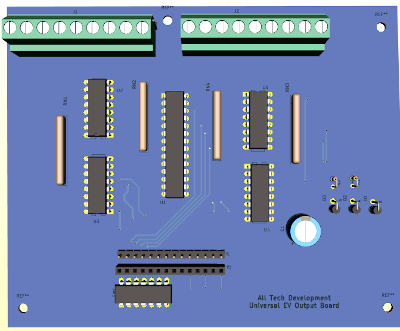
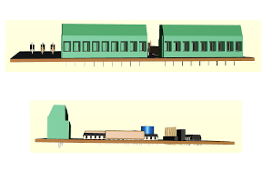
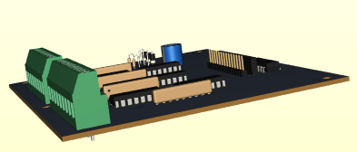
The output boards are 5.2" wide and 4.4" deep. As it stands, the use of LED lights for markers, brakes, reverse, and signals can be easily accommodated without extra provisions. Headlights are the ones that will need an extra relay. Interior lights, fog lights, maps lights and floor lights can also be LED so don't pose a problem.
EV Connections
Starting with the Dash, Remove the instrument cluster and modify the dash for the 10" HDMI touch display. Mount the raspberry pi computer to the back of the display. Connect the HDMI cable to the display and raspberry PI. Locate and wire the ignition switch to the base PCB and connect the cable from the raspberry pi 40 pin connector to the base pcb. At this point supplying 6.4v of power to the power connector will allow programming the raspberry pi and testing the raspberry pi comes on with the ignition switch.
Connect input boards and output boards as indicated. The whole system can be tested at this point. You are looking for input changes to cause interrupts and touch screen actions like turning on and off lights, fan, AC, etc. to result in output state changes. For example see if a pulse shows at the window up/dwn when you try to open or close a window.
My intended frame work consists of 'L' shaped frame that the display mounts to with the raspberry Pi mounted to the back of the display. The base PCB mounts to the flat part of the frame and connects the to the raspberry Pi 40 pin connector. A 'Z' style frame mounts to the back of the first frame such that the input and output boards can mount to it. At this point you need to deside if you want connections to face back or forward and mount the boards. The two ribbon cables from the base PCB need to feed from behind the Z-frame if the i/o connections face forward, or can pass to the boards from the front if connections face the rear of the assembly.
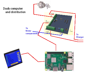
There are 110 wire connections going to the various systems of the EVehicle from the input and output boards. My preference is to wire from the boards to a plate with barrier strips on it organized into purposes. Like put two five contact barriers. Wire the 9 pin mirror wires two the two barriers. Now two cables of 5 wires can go to the drivers door and passenger door to connect the mirrors. The same goes for window up and down. Use four three contact barriers supplied by the 9 pin window connector. A 16 contact barrier will suffice for the seat/door/bin inputs.
 Three different sizes of display to fit any vehicle.
Systems after this point at not in the cockpit they reside in the canopy, back of vehicle or at various light sockets
EV Charger
The charge controller takes
direction from the dash computer and the AC charge port. The computer provides 4 enables (battery pack 1, battery pack 2, Solar, and AC charge). At the AC charge port there is a microswitch that is activated by inserting the plug into the port. When AC shore power is plugged in, it converts 120v AC to 60v AC and if the computer has issued a 'charge-enable' signal passes that AC voltage on to a full wave bridge rectifier to produce 57v DC for charging. As long as the AC charge cable is plugged in normal vehicle operation is prohibited.
Roof top solar panels supply
power when there is sufficient sunlight also to the charging system. It can also be enabled/disabled from the computer. The 2 battery pack enables determine which battery pack(s) to use.
It has two coulomb counters. One monitors charging at 57v and the other monitors 384v discharging and regen charging. The charger also handles switching 48v blocks into series for run mode and parallel for charge mode.
Engine compartment (Canopy):
We don't have a clunky engine and transmission so what we are left with are, a wire cable from the battery 384v supply, and a lighter power cable with +48v, +12v, +6.4v, and ground. This lighter cable then splits with one part going to the dash computer and the other to the board depicted below. A 20 pin connector from the computer then wires to this board.
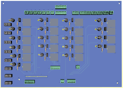
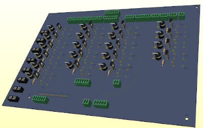
Down the left side are 8 fuse holders, then 6 relays with their driver circuits. These handle the Rad Fan, Coolant Pump, Coolant bypass, Brake vaccuum, Power steering, Inverter heat, Motor Heat. Moving to the right is 5 more relays with drivers that handle The vehicles lighting needs if you are using Incandescent bulbs. If you are instead using LEDs (recommended), these relays and their circuits can be left out. Then to the right of that are 5 more relay circuits for towing a trailer. They are also not needed if you don't want trailer towing. The last 4 relay circuits are needed for the headlights, Hi-Beams, Fog lights and leveler jack if a motor home application.
EV PWM Motor Inverter & Motor
The inverter uses the 384v and Ground from the main battery and control from the ADC board. The control is a combination of 2 temperature sensors, a speed (RPM) sensor, a digital speed request, a direction request and 2 enables. The motor enable activates the Inverter placing it in either run or standby. The drive enable turns on the inverter circuit. So with the inverter turned on (drive enable), the inverter goes to standby and presets motional direction to either FWD or REV then begins sampling the digital speed and motor enable. Upon seeing motor enable the inverter generates the PWM and or VFD at the 3 phase motor field wires and motion begins at the requested level.
Electrical Systems
T he custom truck box we add to the chassis contains Solar panels above the battery banks which in turn mount above the wheel wells. On the left side we have a compartment for a propane powered genset. On the right we have compartment for the propane tank. At the back are two general use compartments. Front to back and between the wheel wells is the normal truck bed. The lighting wiring from the canopy connects to the truck custom box and routes to both tails lights and trailer lights. The main dash system connection connects to the custom box and enters the left side battery compartment. It wires to the charge controller board. The Charge controller which manages 120
AC charge, Solar charge, and handles control signals to select which battery bank is to be run from and which is to be charged. Next we have 8 Gcell Batteries that are 10” x 10” x 12” (32700 type) or
6” x 6” x 6” (21700 type). Each Gcell is secured to prevent moving around. With-in each Gcell is a BMS module to balance the Batteries. An interlock on the compartment door disconnects all
batteries from charging or running the vehicle. It’s like removing the negative wire on the lead-acid battery in your car.
Each Gcell has a switcher board that connects to the battery (+) and (-) terminals and wires to the next switcher in the sequence as well as the charge controler. To
upgrade failing Gcells you simply open the panel, disconnect the Gcell, remove the strap holding it, and lift the Gcell out and exchange it like you would with a Lead-Acid battery. The left
bank we just discussed would be 90” in length 10” high and 12” deep using type 32700 cells. For 21700 type cells it would be 55” x 6” x 6”. On the other side the process repeats only this time we
use the same charge controller.
A 4/0 cable is used in the charge circuit and a 2/0 cable runs along with a multi-wire control line to the Inverter that mounts under the truck bed.
Chapter 10 The Inspection centres
This is the first and last stop for vehicle conversion. When a vehicle comes in from the public or repossesion site it gets inspected for road worthiness. If passed it goes to a dismantling shop and if rejected is returned to the owner unless the failure makes it not fixable.
Again after conversion it must be re-examined to make all work has been done right. It them can be receritified and returned to the owner or sent to an auto lot for sale.
Chapter 11 Class A, B, and C Motorcoach conversion
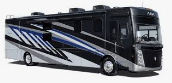
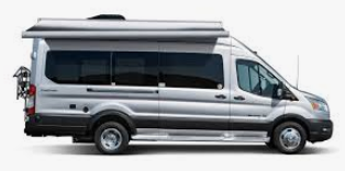
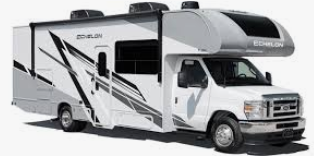 People have significant investment in their RV's which leads to concern for an EV alternative. All RV's at this point are sourced in the USA and with cost ranging from $90,000 to $300,000 each. With Tariffs coming on the scene, the costs can increase to $120,000 to $375,000 or more. The good news is that these to can be made solar electric. Currently only Winabego and Thor make an EV version but for those who have an RV or choose to buy a used RV locally, conversion is with-in reach.
Ideally, the conversion takes the same route as doing a truck. where it changes is with the number of solar panels you have and the fact that a dual charge system is needed. One charge system is used when the vehicle is being driven and handles traction Inverter, regen braking, and solar charging of the bank not in use for traction drive. The other charge system does solar charging of both banks while parked at a camp site and also handles power Inversion to 120v AC if shore power goes out. Potentially, a propane powered genset could also be used to augment range even while driving.
People have significant investment in their RV's which leads to concern for an EV alternative. All RV's at this point are sourced in the USA and with cost ranging from $90,000 to $300,000 each. With Tariffs coming on the scene, the costs can increase to $120,000 to $375,000 or more. The good news is that these to can be made solar electric. Currently only Winabego and Thor make an EV version but for those who have an RV or choose to buy a used RV locally, conversion is with-in reach.
Ideally, the conversion takes the same route as doing a truck. where it changes is with the number of solar panels you have and the fact that a dual charge system is needed. One charge system is used when the vehicle is being driven and handles traction Inverter, regen braking, and solar charging of the bank not in use for traction drive. The other charge system does solar charging of both banks while parked at a camp site and also handles power Inversion to 120v AC if shore power goes out. Potentially, a propane powered genset could also be used to augment range even while driving.
 Maybe your needs are better suited to a Solar-Electric Tricycle for going to and from work, grocery shopping or trips to sports or gym activities. Canada can easily make these starting around $3000 each with speed up to 50 kph and range from 80 to 500 kms.
The solar electric tricycle is more stable than a bicycle and fully street legal. You don't need a drivers license or insurance or fuel. That means that if it suits your needs you can save $1000 for insurance, $2500 for gasoline, maybe another $1000 in yearly maintenance for a potential of $4500 a year towards a new ride.
Maybe your needs are better suited to a Solar-Electric Tricycle for going to and from work, grocery shopping or trips to sports or gym activities. Canada can easily make these starting around $3000 each with speed up to 50 kph and range from 80 to 500 kms.
The solar electric tricycle is more stable than a bicycle and fully street legal. You don't need a drivers license or insurance or fuel. That means that if it suits your needs you can save $1000 for insurance, $2500 for gasoline, maybe another $1000 in yearly maintenance for a potential of $4500 a year towards a new ride.
Chapter 12 Conclusion
In conclusion, Canada can become the World leader in Climate change matters. We have the resouces, the man power, and the potential. We can make new markets to supply our food, clothing, and assorted product needs. We can offer our products to these markets, I am thinking of EV-Trikes to not just Canadians but also to developing nations, and even the UK, or EU nations.
To use a twist on what Trump said. "We don't need the USA gas and oil, we don't need their dairy, cattle or poultry. We don't need their steel, copper, nickle, aluminum, uranium, lithium, fresh water, potash." He can Tariff us on all these goods going south but we don't pay only his businesses or consumers pay to get what we have. We can reciprocate with Tariffs on stuff coming into Canada and be hit export Tariffs by Trump. If we don't buy from America we don't pay anything. So in the end, Canada isn't buying from the USA so neither Canada nor the USA makes anything from Tariffs. If the USA wants our steel, copper, nickle, aluminum, potash, uranium, it's his US customers that pay the Tariffs. We could raise the price on Canadian resources and impost an export duty but what would that do.
Trump says he'll put 100% Tariff on Canadian made cars which of course would kill the auto sector jobs up here and deprive the US auto market of 90% of the cars we would make. He at this point is counting on Canadians buying USA made cars, trucks, vans, etc.. Not if I have my say on things. I have outlined new industries focused on green net zero that will offer a high rate of return to Canada.
Our net zero target by 2050 was derailed by the oposition parties and premiers and I see why. The Liberal government expected the whole country to shoulder the burden of going green. People struggling to put fuel in their cars, heat their homes, buy groceries and hope not to lose their homes or jobs have little interest in climate change incentives. Personally, if you want to achieve a goal you have to lay out the plan with concrete targets, define the roles of all participants, bring in the participants and make the presentation. The liberals did set the targets at each level, and did introduce the carbon levy and implemented it. They did not offer incite from business or premiers or discuss ways to achieve the targets. And they didn't present the plans to the people. Trudeau can use air time to discuss his glorified budget, or his address to the nation but can't bother to go into details of how the business's , premiers, and the people can play a role.
The move forward:
What I have to say is pulling no punches. I am sorry if I ruffle feathers. Canada focused on trying to guess what Trump wants, when he said secure the borders maybe he would lax off. Well securing the borders is good and we do have a problem if even a gram of fentynal goes south or a single person gets into the USA illegally. On the flip side, the USA needs to secure it's borders too. Too many Guns, Drugs, and illegal immagrants are comming into Canada from the USA.
Canada formed a united Canada first group of premiers to address the Trump tariff problem and choose what actions to take. Alberta's Danielle Smith originally didn't side with Canada First and did 2 private meeting to secure a personal deal with Trump. This is clearly a case of treason against Canada and while she came home confident she succeded that was short lived as he placed a future Tariff on energy products entering the USA. She now is with the Canada First deligation. Trudeau went to the UK and EU to secure more avenues for trade which is great. Trump is making so many changes to the US and affecting the whole world that he hopes will have them so off balance that they can't react. He is just a bully that figures everyone is doing him wrongs. The premiers in panic mode travelled to the US to plead their case. Did they get to see him. NO they got to talk with underlings that are scared of their boss / bully.
While this is going on, Premier Danielle Smith hasn't been tending to her job in Alberta as Jasper residents have no homes due to the fire devastations of last summer. She also was not present to address the health issues that have come up regarding the AHS restructure she was doing. Premier Doug Ford is also not doing his job. He is splitting time between promoting his province to Trump and doing an unnecessary election campaign and ignorring his province. A province that has many homeless in the dead of winter and a health system in shambles.
The united Canada First Premiers have decided to work on removing inter-provincial trade borders. I realize the premiers want to protect their own provinces but they are not selfish kids anymore so quit acting as brats. How much effort does it take to take each item of the trade issue and then in 13 columns list the current rules spreadsheet fashion. Example is alcohol in Quebec can sell to Saskatewan and BC but nowhere else in Canada but can export to the world. I met a person from Quebec that is in Alberta that ordered alcohol online from Quebec to ship to an aunt in BC and the aunt then sent it to Alberta. Rediculous. They say things can probably be resolved in 30 days on many issues but credentials of trades and electrical rules will be a problem. Pure crap. I could never think as slow as these polititions if I tried. I have the Canadian standards for electrical structures listing all the electrical compliance issues by province and in 6 provinces outlet boxes need to be metal with ground tag, do not need vapor sheilds around the boxes and wires must be 5" extending from the box. Other provinces say 6" extending and still others say 3" extending. Some provinces allow plastic outlet boxes, others say vapor shields. Make set standard and everyone is on the same page. The Book has thousands of these inconsistances.
Our new industries will employ the talents of welders, mechanics, tow truck drivers, detailers, inspectors, and Transport drivers to name a few. With about 34 Million vehicles to convert, we will have about 10,000 per day to do and work for 15 years. The new industries may expand some existing ones like steel and aluminum fabrication.
New Industries
- Repossesion and Auction sites: Source for vehicles with conversion potential
- Dismantle Centers: Located in provinces and teritories 10,000 units /day for 15years
Vehicle inspection, required maintenance, remove ICE parts for disposal.
- Recovery centres: accept and crush metal debris
- Electronics factories: 10,000 units/day for 15 years
Make Universal Dash computers, charge controllers, bank switch boards and BMS boards.
- Solar plants: up to 100,000 units/day for 15years
Make 4 types of solar panels for cars, trucks, bus's, motorcoachs and homes
- Battery factories: 160,000 units/day minimum for 15years
- Motor plants: 10,000 units/day for 15years
- Transmission Shops: transaxle transmission adapting and gearbox manufacture.
- Conversion Centers: Located in provinces and teritories 19,000 units /day for 15years
Do vehicle conversions, final unspection and certification
- Auto lots: Source for converted vehicles for sale.
- Solar Electric Tricycles factories:
In the end we are totally self sufficient and Net Zero.
New Battery standards
In the coarse of preparing this evaluation a New standard was developed that identified 3 classes of battery Gcells to deal with vehicle conversions of all types to EV. Each class has my original 32700 type cell and the new lower priced, lighter 21700 type. With standard Gcells we can service vehicle packs and home solar storage implentations.
The battery Gcell standards makes it possible to source replacement Gcells from local stores and make owner replacement possible. Also developed was a plan to do banks instead huge packs so an EV conversion can be done in stages if funds are tight and this also enables solar charging.
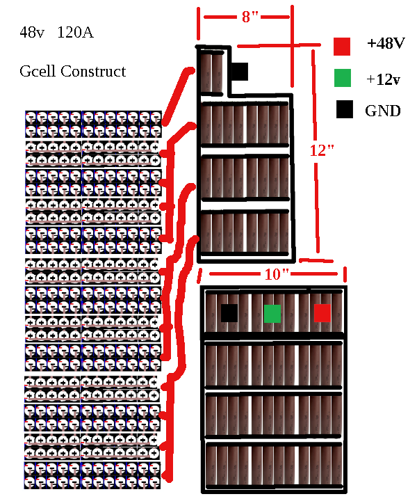 To enclose such a Gcell you want it to be safe for operators, ventilated, short proof (conductivity safe), and reasonably light. In the above scenario, in each case we get 84A to 120A Gcells which are about the same as standard 12v lead acid battery. By the time you add $3500 in motor, Inverter, and Dash computer and charger-switcher a vehicle conversion shop can likely convert a car or truck starting at $10,220 + Labor. No matter how you slice it, 16x 12” cubes for battery brings great promise and cost effectiveness to converting regular vehicles to EV.
To the left is a 48v 120A Gcell layout which is 8" x 12" x 10"
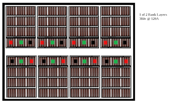 As I discuss this Gcell construction for use as a power source for an electric vehicle it can also work as a storage source in a home solar electric system. In the home situation solar power charges the batteries and at the same time an inverter converts 48v DC to 120V AC or 240v AC to run the home. When the sun goes down the batteries power the home. When the batteries are depleted the power grid supplies the home. The government is offering money to some area’s for people to go solar electric. The UPC party and Danielle smith don’t want you to have free power from the sun because that means lower oil & gas revenues.
Universal EV Dash Control system, and Coach charge controller
Amasingly a Universal control system in 3 sizes was developed that can be used on all EV conversions. For Motor Homes, a separate Coach charge controller was developed.
Thank you for reading