Front Lighting control (applies to all E-trikes)
It gets it's 6v operating power from a 6.3v tap at the batteries, and it's Light power from the mains. A slope top cabinet houses the lighting control, Master key lock (not shown), Headlight switch, and Hazard switch. The front will have the left turn, right turn, cylon / Kitt-car eye assembly mounted through the windshield. Battery voltage and status mounts to the top surface as does the speed/odometer display.


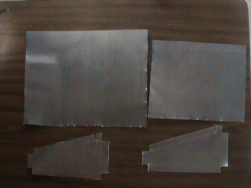
I originally was going to buy a slope front plastic box to house the system but, and there is always a but, elected to make my own metal enclosure. At the time I needed rivets to complete the signal switch container and since a piece of metal to do the console and the rivets came in less than the plastic console would cost, it made more sense to me. First I marked out the pieces and cut them. To seal against moisture seepage I applied rubber, obtained from an old inner tube, between the Front, Base, and Back and the sides. Rivet holes were aligned and pre-drilled on all associated surfaces. Starting with the front-bottom-back, it is bent into shape and riveted.
For the top, self tapping screws through rubber into the lip are used. A printed front panel is laminated and applied to the top surface.
The board fits nicely using 5.4" x 5.75" of the 7.5" x 5.85" console. Operation of the board is done using the 6.3v battery tap. Lighting is done using relays so the board handles 24v or 48v systems with the only caviet being that lighting strings attached must match the correct 24v or 48v system.
The schematic below does all including the brake lights, brake control, and motor cut-off of our system. Front turn signals and markers and cylon eye mount to the front edge of the board. Switches mount to a pin header in the middle and rear lights mount on the right side. The two signal leds will actually mount to the top lid. The headlight and horn mount to the bottom of the light control unit. A PWM Brake solenoid connection powers the brakes as needed. At bottom left provides power from the Main control unit in the electrical compartment. Finally the key Switch connector provides for Master system power the location of the key switch can be on the front control unit, Right handlebar grip or anywhere else found desirable.


At the left are the switch and sensor inputs that come in on the pin header. All switches and sensors run from +6v @ 20ma max. Four opto isolators handle motor cut-out if either brake handle is activated and at the same time powers the brake lights. Where the accelerator at the right controls speed and is not part of this board, the left decelerate at the left hand grip does come into this board and feeds the PWM circuit to regulate the amount of braking to occur.
The heart of the lighting control is a flasher timer. It runs as long as the trike is powered. It has a speed adjustment to set the flash rate. The cylon eye uses this flash rate to move the eye back and forth by lighting individual leds. This is accomplished by 74191 binary up down counter and a 74151 1 of 16 demultiplexer. Half of a 7473 jk flip flop changes the count direction. Two dpdt relays are used to provide 4 corner signals. The signals are flashed by use of signal light switches that connect the flasher to the appropriate relay. If the hazard button is pressed both relays get the flash pulses.