|
Finishing Up: Lights first
At this point we have the completed E-trike with one exception. To be street legal we need full lighting package, and a full working braking system. A Windshield, helmet, and gloves also will be needed.
I had planned on adding the lighting system below up on the handlebars till I realized there was no way to implement motor cut-off and brake lights. So, I made a change that involves a new lighting controller mounted between the handlebars and windshield with new circuits and custom lights.


|
|
The headlight and Cylon/Signal Lights

|
Ideally we want the Cylon eye generally inline with the handlebar at the center. The lighting unit needs to be perpendicular to the windshield and mount to the handlebar and windshield. The headlight needs to be through the windshield probably below the Cylon eye because the control unit has switches and displays on it's top. As such, the headlight will mount to the bottom of the lighting controller to the front.
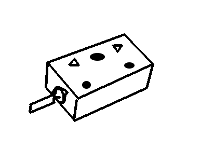
Now for our custom lights. The concept here is that I have the lights assembled and tested on their circuit board. A piece of clear 1/16 " Plexiglas is formed into a 5 sided box made to accommodate the PCB. PCB wires are fed through the base and box is filled with clear epoxy resin. Another clear Plexiglas is secured to the open side with acetate glue. The finished assembly can be drilled and mounted as a sealed weatherproof fixture to the sloped top front controller.

|
|
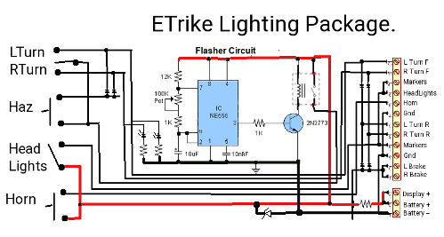
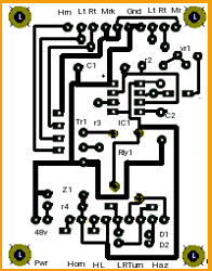
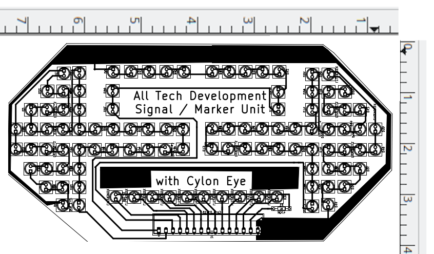
For the front we have a left turn / right turn / marker / cylon eye board image followed by the size spec the top and bottom board layouts and the schematic.


Lighting control Unit
When desiring to mate two boards (in our case the light panel to controller) it is essential to match up things in the design stage before you make the production ones. The mock-up can identify possible problems before committing resources.

Actual size of our front display identifies a height of 4" and width of 7.3" mating with a control board 5.2".
For the markers, we take the front marker line feed it into one marker board, connect the output to a terminal strip, and also feed that strip with a blank wire, Left signal, left brake, and Ground. A sixth wire goes on the terminal strip and then all six pass to the other side. On the other side we take the marker wire and feed it into the marker board and take marker output and all the other wires down to the left tail lights. On the right side we feed Right brake, Right turn, +48v, and the blank wire to the right tail light.


Each of the two taillight assemblies are the same just oriented so the LED arrows face out.


|


