Electrical Compartment
In the original plan I was going to use a series of off the shelf units but, and there is always a but, this proved to be expensive and overkill in some aspects and lacking in others.
The cell logger would cycle showing the voltage level at each cell and sound an alarm when any cell drops below 2.8volts. It would take 2 units for 15 cell groups. Instead, we will use a voltage display up front. It will show 48v at full charge and 43v when depleted. There will also be battery state display.

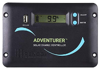
A fancy solar charger shows volts and amps from the solar panel, and blocks draining the batteries when the sun goes down. A simple pair of diodes does the same job for under $1

A balance charger can handle 8 groups at a time, but using passive BMS and our custom charger we can do all 15 groups at once.

An inverter converts 48vDC to 120 vAC but again is bulky and costly. Our custom controller takes less space, less expense, and will give limited but adequate power.

The ebike controller is all we must have and it comes with our front wheel hub motor.
On the face, there is a mode switch, 120v AC single outlet, and charge port. The Mode switch selects charge battery, charge from AC, AC power out, or E-Trike drive mode, and of course Off.


The E-trike controller is going to be the hard part in wiring. The mode switch tie the 48v Battery bank into the ebike controller from the main controller but everything else from the controller has to be run to the amenities. We are talking 5 wires to the pedal sense, 8 wires to the front hub (5 sense/3 power), Accelerate, brake, signal & light power, Speed & battery state and Key switch all up at the handlebars.
The Main controller


The Circuit Objective
This is a combining and rework of systems outlined by Swagatam Innovations featured in homemade-circuits.com. Using 3 independent circuits outlined, I reworked them such that where circuit 1 took 230v AC shore power which activated 2 relays (one was with momentary delay) to supply 230v AC to an appliance and also supplied a 230v AC to 12v DC half wave charger through a center tapped transformer. Now circuit 1 takes 120v AC and supplies 120v AC to an appliance, uses a 120v AC to 60v AC non center tapped transformer to supply a full bridge rectified battery charge at 56v DC.
The Inverter stage of circuit 1 used a simple oscillator driving 2 mosfets which fed a center tapped transformer in the reverse direction with directional control provided by the 2 relays mentioned above. Now by using a non center tapped transformer, 6 P-channel mosfets and 2 N-channel mosfets to provide the inversion. Thusly, circuit 1 and 2 are combined with a notable exception. Circuit 2 used a third relay to switch the battery from charge to invert and it was changed to the mode switch so that I can achieve an off state when no charging and no inversion is desired. Due to cost and availability issues handling relays with 5A and switches with 5A to 10A ratings, the board was revised to use opto-isolated Triacs and Triac switching stage. Now 6v @0.02A handles all switching.
With the third circuit, we add solar charge/run, Ebike drive power, and Battery bank charge or assist from solar. When solar is deployed (uncovered) solar power charges the battery. The load output of the third circuit goes to the Ebike controller which can now draw from solar and or battery.
At about 5" square the system board is fairly compact with an off board transformer being the biggest part.
From our compartment box we have to pass the wiring along the lower frame to the center where it must then pass to the front section and be routed through our moved upper frame section and out to the handlebars. The pedal sense wires come down the seat down pipe to the sprocket. Thus far we can have all the wiring concealed. When we reach the handlebars 8 wires can pass along the front fork down pipe to the front axle with no problem. At the handlebars we then have a huge clump of wires going to brake levers, display, throttle, master key switch, our yet to be included lighting package, and from this lighting package to horn, front markers/signal, rear marker, signal,brakes, and headlights.
Charger / Inverter
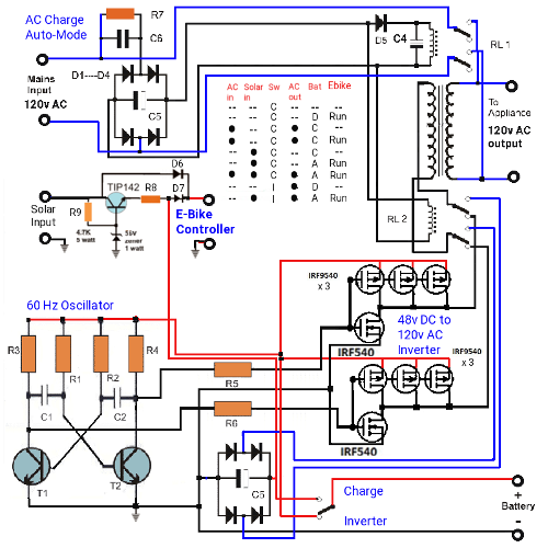
This adapted bad boy controller has a lot of integrated systems in it for total E-bike control. Comprised of 6 sections, It handles AC Input, Solar Input, Battery In/Out, AC out, Oscillator, And Inverter.
Function Mode Switch While this is not a system, it does determine what systems work and when. In the charge position, you have AC charge when the AC power cord is connected which also provides AC appliance output, Solar charge with solar available for run assist, E Bike Run. In the inverter mode AC appliance runs from battery, and if solar power is available it too can supply both inverter and Ebike power.
AC Line cord when plugged in to land power makes AC charge mode available at the switch. It can supply the Appliance power and Battery charge directly. An off board breaker limits current to 5A @ 120v AC input with up to 5A available for appliance use and up to 10A for DC 10A charging of the Battery.
Solar charge / run when the solar panels are deployed and given enough solar energy, the 60v Solar panels can supply 2A of charge and run power to the system. The E-trike demands 10A to go 40 to 50 kms so technically, having 2A assist should ideally extend travel to 48 to 60 kms on a bright sunny day, or reduce depletion of the battery. Changing the size of solar panels effectively doubles charge to 4Ah
E-Bike drive is given it's power from one of or all of the Solar Panels (60v @4Ah), or Battery 48v @30Ah. The controller for the E Bike takes a 48v to 60v input as it's drive power through a master key switch at the handlebars. This same key switch controls all functions of the E-Trike.
Battery supplies 48v @30Ah for either running the E Bike or Running the inverter in Inverter mode. It is charged with BMS with balancing function at the Battery pack and gets the charge power from the Solar panels or the AC charger.
Inverter when the switch is in inverter mode, the Battery supplies power to the oscillator and the inverter drive to convert 48v DC to 120v AC @5A maximum for up to 2 hours.
Oscillator supplies a 60Hz multi-vibrator control to the inverter mosfet stage of the inverter. As a multi vibrator circuit it supplies 60 positive going pulses and 60 negative going pulses in an alternating fashion.
The charge / Inverter defined here uses a single Transformer that works both as an inverter and a battery charger.
E-Trike Charge and control Schematic
Typically, a transformer is used when going AC to DC or DC to AC and in this design we are planning for a single transformer to do both. If primary voltage is 120v @5A, output is 60v @11A on the selected transformer. Wattage remains the same. Transformers are rated by their wattage spec above all. So in our case 120v AC @5A is 600watts. The selected transformer has a dual primary and dual secondary and a 625watt rating when both primary and secondarys are in parallel. The bridge drops 2.7v leaving 57.3v for charging. In inverter mode 48v is inverted to 96v AC @5A which isn't ideal but for running some power tools will suffice. The batteries can be charged up to 6A each but doing 15 groups, the charge at each battery is only 740mA.

Two views of the schematic from two CAD programs. On the left is the reworked design which had problems handling currents. On the right is a corrected circuit designed to fix the problems.The oscillator and inverter stage is kept. But instead of using an AC to DC from the AC input and relays to provide the switching, it uses a low voltage - low current switch that powers a set of opto isolated triacs to handle AC switching at up to 15A. We use a 6.4v tap at the battery pack to supply the selector switch which in turn supplies the selected opto-triacs with about 20ma. In invert mode, this same supply feeds the oscillator.
The look of the resulting PCB board reveals DC connections across the top and AC on the left side with selection at the bottom left. The front of the compartment has a surface area of 6.5"W x 12.5" so if I make a metal cabinet 6"W x 9"H x 3.5"D, I can mount the AC In and Out sockets and protective weatherproof cover at the top with the circuit board rotated 180 degrees below it. the left side (from the back) can hold the terzoid transformer and the right side Circuit breaker. The DC connections come in through the bottom and the unit can then mount against the outside surface. The E-Trike controller can mount against the back wall so there is a home for everything.


Wiring for the master control is abbreviated here. As can be seen, the solar and battery simply connect direct to the board although for servicing it would be prudent to wire to a barrier strip. The ebike controller also is shown as direct connection although it in reality has a key lock switch up front. The transformer has dual primary and dual secondary and these are wired in parallel resulting in 120v-ac to 60v-ac. The AC in and out needs a circuit breaker for in and out. The depiction below is an old one before I fixed the problem with current ratings.

A simple metal enclosure will suffice to hold the board and provide mounting surface for the transformer, barrier strip, and panel mount circuit breakers.
I moved the doors to the side and mounted the electronics to the front surface as it worked better.


The facing of the compartment is 15" H x 8" W. The frame is .75" square tubing to leave a surface for mounting of 13.5" H x 6.5". I construct a simple metal box with 2" sides to conform to the needed 6" W x 12" for the electronics. I also construct a lid 6.125" H x 12.125" with 1" sides. Before bending the sides, I measure and place 6 unit mount holes, Selector switch hole, and the almost square AC charge and AC outlet holes and the PCB mount holes. Then using the piece as a pattern place the 6 unit mount holes and switch and AC holes onto the outer compartment panel.
With the unit enclosure tempoorarily mounted into place the AC ports cover is lined up and it's center mount hole placed. With all this done we can then remove the enclosure and install the circuit board stand-offs, wire up the switch and AC sockets and attach the wires for the transformer, Ebike controller, Battery, Solar and front controller to the PCB. Mount the PCB and barrier strips come next. The chassis mount circuit breaker then needs to placed on the side of the box such that it will be accessible through the side door.
Wiring for the front, Battery, Solar, E- Trike controler, enter through gromets on the side furthest from the door and go to their respective points on terminal block. The transformer mounts to the lid on the outside and it's 8 wires feed through gromets in the side and wire to the barrier strip after the unit is mounted into place. There is provision for a custom ebike controller PCB and associated barrier strip for other versions of E-Trike.