Making the electrical compartment
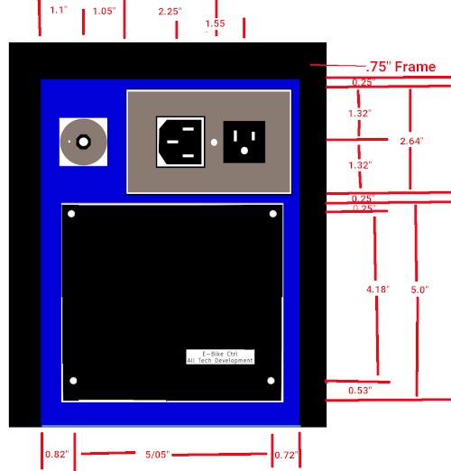
Below we have the front of the electronics cabinet. At 6.5" x 8.75" it will be a tight fit between the 0.75" compartment frame uprights. It is secured to the outer compartment skin and has mount holes for the PCB and Mode switch and the two almost square AC connectors through both the skin and the front of cabinet surface. The AC socket connectors are designed to just pass through the cover plate such that the cover closes flush. There is tiny mount tab on the switch that must be sealed to prevent water seepage into the cabinet.

The top, bottom, left, and right of the cabinet extend at least 2" into the enclosure. A push button circuit breaker mounts through the back and the back screws onto the cabinet.


Above are most of dimensions for mounting the items.
Wiring it all up.


All is for not without wiring it all up. I have talked about a fair number of systems and features of this E-Trike and it is time to try to interconnect them all.
The front Wheel has 5 wires going to the electronics compartment's ebike controller. The speed sensor wires to the lighting controller at the handlebars.
The left and right handlebar wiring goes to the Lighting control box on the handlebars. However, the throttle wires go to the ebike controller in the electronics compartment. Headlight, horn, front turn signal unit fit directly onto the Lighting control unit which also contains the the headlight switch, Hazard switch, and main key lock switch. This Lighting control unit has the Lighting and brake PWM PCB. The brake PWM has the job of monitoring both brake levers to report to the ebike when to stop the motor power and to generate a PWM servo signal to apply brakes.
From the lighting control we have 4 possibly 5 cables that come towards the back electronics cabinet. The PWM cable stops at the brake servo at the front to back frame joiner. One or two cables (for accelerator and optionally PAS) goes to the ebike controller. Of the two remaining cables, one goes to our main controller and the other to marker and tail lights. Finally there is 6v and 24v and key lock and GND which works something like this, The Battery has 24v which travels first to the key lock switch. A 75v 10A diode is across the switch so that the battery may be charged even with the key off. The 24v from the key lock then goes to the Light and Brake PWM PCB before going to the electronics compartment. The Battery 6v line connects to the board before going to the electronics compartment.
Front lighting control marker(+) goes to Right side marker (-), Right side marker (+) goes to Left side marker (-), Left side marker (+) goes to Left rear marker (-), Left rear marker(+) goes back up the left side and across to the right side and down to Right rear marker(-) and finally Right rear marker (+) goes to +24v. Left Brake, Left Turn, GND go down the left side to the tail light. Right Brake, Right Turn, GND, and +24v go down the right side to the tail light.
Two wires from the solar panel go to the electronics compartment. A 5A circuit breaker connects to the AC in plug hot line and to the main control board. The AC in Ret line and both AC out lines go to the main control board. Both AC neutral connect to the chassis frame. The main control board then gets +24v, +6v, GND from the front lighting control. A 6 position switch at the compartment wires direct to the board. The solar panel and the ETrike control connect to the board.
Finally, The E-Trike controller which gets it's power from the main control board, has the 3 wires from the throttle, 5 wires from the hub motor, the brake cut-out line and possibly wires for POS (Pedal assist) , speed, and battery status if so equipped.


