Solar Array Installation
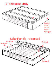
Using the plans set out in Vol 2 on the making of a solar panel for an etrike, we will construct a 2 panel, 48v 4A solar charger. The 2 panels will mount to the top behind the bike seat end and fold up one on top of the other when not in use for charging.


The tables below form the foundation for available space and cell count and arrangement.
| Solar array area: | ||||||
| # of panels | width | length | cell width | cell length | cells/panel | cells/array |
| 1 | 46" | 36" | 42.5 | 34.5 | 168 | 168 |
| 2 | 46" | 18" | 42.5 | 16.5 | 84 | 168 |
| 3 | 46" | 12" | 42.5 | 10.5 | 42 | 126 |
| The area specs above determine total space for inclusion of 4" x 2" cells. It includes the spacing between cells and accommodation of the framing. It does not cover how the cells are wired or their configuration. | ||||||
| Solar charge requirements: | Charge Voltage |
Series Cells |
Parallel Branches |
Total Amps |
Total Cells |
|
| 30 | 60 | 1 | 2 | 60 | ||
| 30 | 60 | 2 | 4 | 120 | ||
| 30 | 60 | 3 | 6 | 180 | ||
| 57 | 114 | 1 | 2 | 114 | ||
| 57 | 114 | 2 | 4 | 228 | ||
| 57 | 114 | 3 | 6 | 342 | ||
| As can be seen, in a 36" x 46" charge area, we can handle up to 4 amps @ 24v system and 2 amps @ 48v system without doing anything special. we are 12 cells short to make a 6A 24v system and 60 cells short of doing a 4A 48v system. We are restricted to the 46" tricycle width but can go another 6" past the end of the trike with a foldout panel for 6A @ 24v. A 12" foldout past the end would barely provide 4A @ 48v system. If it isn't clear, when I talk of a 24v or 48v system then charge requirements is 30v and 57v respectively. | ||||||
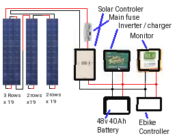
| Solar wiring. Each row of cells develops 10.5v in series, so a 24v system needs 3 rows per string and 48v needs 5.7 rows. Using 18" panels we can have 4 rows per panel so 1 series string uses .75 panels for 24v and 1.5 for 48v. 2 series strings is 1.5 panels for 24v and 3 panels for 48v. 3 series strings 2.25 panels for 24v @ 6A. A micro switch needs to be incorporated to switch the panel into circuit when it is deployed. |
||||||
Solar construction
For the frame structure you need Aluminum 'U' chanel that can accommodate .75" of material I.D and given that Aluminum 'U' chanel is typically .125" thick you need to have 1" x .6.25" O.D. "U" chanel. You will be building 2 boxes that are 18" x 46". The panel substrate (backing for the cells) is .5" Plywood cut to fit snug in the boxes. This will leave .25" space to accommodate .125" spacer and .125" of drop ceiling lens. I glued .5" x .125" lens to the edges of the plywood then drilled and screwed 3 of the 4 edges of the "U" chanel to the plywood. The fourth edge will be applied after the lens and cells are done. If all goes well you have a plywood surface 16.5" x 44.5" to place the 4" x 2" cells. Tabbing wire is soldered to the back of each cell and is the (-) of the cell. The tops have the (+) of the cells.Before proceeding, it is prudent to point out that there are many options to making custom panels. You could place panels over the side compartments and fold the inner panels over the outer for storage or stay with just 2 full width ones. As depicted below, the over the compartment style provides 28v or 56v charging while the full width provides 30v or 60v.


The polycrystaline cells are very fragile. To start each row of cells, Solder a Buss tap to the two negative tab wires of a cell. align and glue the cell into place. It is prudent to draw the cell placements onto the plywood such that each row can have 21 cells with 1/8th " spacing on all sides. As you add cells, cut the tab wire such that they do not extend all the way to the edge of the previous cell. You solder the tab wire (-) to the top of the previous cell (+) and glue the cell down observing the 1/8" spacing. I added a bead of rubber cement at the edge of the previous cell to eliminate chance of shorting the positive and negative of the previous cell together. At the end of a row, solder 2 tab wire to the positive of the last cell and add a Buss wire that must carry over to the next row (-). In this fashion, the first cell (-) will be at the opposite end as the previous cell row. Doing 20 cells per row will take 3 rows for 24v. Doing 21 cells per row you can achieve 84 cells in 4 rows of the required 114 cells for 48v.
To join one panel to the next, we need to connect the buss tap (+) of the last cell to the negative of the first cell of the first row in the new panel with a wire. In the second panel it wires up just like the first but, and there is always a but, This time we use one row of 21 and only 9 in a second row. The solar array (+) from the end of the second row feeds into the first panel and the first cells (-) of the first panel and the positive from the second panel feed into the electrical compartment as a 57v @2A solar system. To make a 4A system, we start by sacrificing 1 cell position at the end of panel 2 second row position 10 so we have space for a starting cell (-). We run a wire from the (-) Buss tab into panel 1 and attach it to the (-) of the very first cell. We can then continue to do the cell row and the next 2 rows. By the end of the 4th row we have 53 of the required 114 cells so we need 1 more panel.

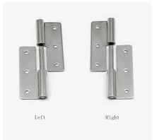
If you are lucky and can get pin hinges, you can add a two pin plug connector and wire the one side to the fourth row (+) buss and connect the other side to the second row (+) buss. We need 61 cells (3 rows) in the add-on panel. So a 14" wide panel will do and wires in a similar fashion to panel 2 except it will have a plug connector. In the end you have 4A of charge.
The controller will have a 57v 4A diode to block the panels from discharging the battery pack when there is not enough light to induce charging. When the panels are not deployed a simple micro switch will prevent them from connecting into the circuit. Where the charge current from the solar array is 4A maximum, this provides a small charge at 0.25A to each cell which is very low. It would take 24 hours of continuous charge to come close to a full charge. Given that there is less than 8 hours of usable sunlight in a day, there is no risk of overcharging.
When riding the bicycle, you are using 10A to go 40km out of the battery. 4A of charge adding to the main line, may reduce the battery draw by 4A to be 6A of battery depletion over the 1 hour trip. Then while sitting at the destination for an hour or two would further recharge 4A to 8A and thusly replenish the battery. In this manor, range is somewhat extended. Where you would expect a 80km trip to deplete 20A from the battery pack, a 4 hour round trip with solar charge at peak would result in 6A use on first leg of trip, 4A recovery waiting to return, and 6A ideal drain on the return. So total power used was not 20A but only 8A.
As stated under the Battery section, we are planning on raising the battery from 20Ah to 30Ah so our range has gone from 80km to 144km. Under ideal conditions, we could see 120km in 3 hours with 30A draw but supplemented with 12A from solar meaning we only used 18A. This leaves us with only 18A available if we turned around and head right back. Our battery would die on the return trip 3/5ths of the way home if we lacked good sunlight. We would need at least 3 hours of good solar charging just to barely make it. But we do have on board 120V AC charging at 10A so if we could plug in on the trip at the destination, we could replenish the charge in 2 hours.