Travel for free with an EV
Motorhome
Wow a big topic fitting for of a book of it's own:
It's high time to move away from the ICE (internal combustion engine) and all that goes along with it. For years I have watched the coming of electric vehicles with hopes of having one myself. I've endured the
hardships of a diesel truck with FICM troubles, Cars with mechanical troubles all related to engines that suddenly just won't run. Even converted a mini-van to run on propane. Then came the Motorhomes which drank gas like crazy at 4 to 6 miles per gallon. After sitting for prolong periods in campgrounds it became a roll of the dice as to whether or not it would start.
Having to regularly start them every week just to cycle them so the filters don't seize up or plug. Wasting fuel just so when the time comes they might run. In 2015 we fought for two weeks to get the motorhome going so we could move to a
new location. At the new location weekly starts became more of a monthly thing due to starting troubles. Then in 2017 when we got news of the campground closure, we had a parade of mechanics come with no success. Engine is fine but no fuel for ignition. End result is a big $1800 charge to tow the vehicle 160km to Rockyford.
Mom summed it up right when she said "this is the final straw. You know electronics, you know computers, you have made so many things so you are mechanical, SO WHY
HAVE WE STILL NOT GOT AN ELECTRIC MOTORHOME."
The subject of a fully electric motorhome has many tentacles. The motorhome uses Gas or Diesel as it's fuel for drive-line operation, Propane for cooking and heating of water and for the furnace and refrigerator. The Gen set supply also uses Gas or diesel. Appliances use 120v AC and 12v DC and the trickle charger for 12v uses conversion from AC. Gas and Diesel produce high amounts of greenhouse gasses, are 20% efficient over-all, and are the major contributors to
high maintenance costs. Propane burns clean with little greenhouse Gasses, and is 50% efficient. Electricity has two parts. During generation there may be greenhouse gas produced depending upon the method used to supply power to the grid. During use by people and equipment drawing from the grid there is no greenhouse gasses and efficiency is above 85%.
A look at the changes to be made reveals:
- Remove 48 cu. ft of engine & replace with 1.6 cu. ft of electric motor & Inverter
735 lbs replaced by 140 lbs.
- Replace vacuum brake booster from engine with electric vacuum pump, replace power steering pump with electric driven type, replace AC compressor with electric version.
- Remove exhaust complete with catalytic converter, muffler, and tail pipe -85 lbs.
- Remove fuel lines, inline filters, 80gal fuel tank, and fuel -535 lbs
- Remove transmission -130 lbs, remove doghouse over engine and replace with flat floor access door -60 lbs.
- When we intend to move we drain -500 lbs of fresh or waste water.
- Replace propane water heater 60 lbs with electric instant hot water and move electric hot water into heated space.
- Replace onan generator on gas or diesel to the propane equivalent
- Remove 5 x Lead acid batteries -425 lbs
- Add 2 x 384v battery banks 100 to 600 Kwatts
- Add solar array to roof
- Add EV operation computer up front and charge system in back for enjoying RV life while parked.
This outlines what is involved. We
eliminate about 2535 lbs of ICE stuff and add back 140 lbs of
electric motor & Inverter but place them back near the rear
axles. Compensate for engine related systems with electric versions. We improve our living space by not having the doghouse between the front Captain seats and further improve with on demand hot water using an electric water on demand heater instead of a propane heater running 24/7. There is no more gas or diesel fuel so we switch the generator to propane. We remove 2535 lbs from the vehicle and add back 140 lbs of Motor/Inverter. So we have 2395 lbs to use for batteries and solar charging.
In the chapters that follow I will discuss theory of operations on these 12 points in an effort to approve or disprove modification of a large Motorhome as a viable EV
electric conversion.
Introducing EV ground work
The average person drives 34 miles
per day (56km) which is 12,410 miles (20,683km) per year according to the insurance bureau of Canada. On vacation they may take on trips of 500 miles in their truck/trailer or motorhome and travel that distance 2 ways each vacation. Upon retiring more and more are choosing to live their remaining life as full time RV’ers traveling to see the country. In their working life their vehicle ranged from 10 to 30 mpg and cost them $3.85 to $17.04 for fuel daily and $1405 to $6219 a year using today’s prices. Vacations could cost them an
average of $833 in fuel. The full time RV’ers may travel in spurts of 70 to 600 miles with stopovers of a week to 2 years between the jaunts so their fuels at an average of 6mpg runs them $58.33 to $500 in fuel each move. It is not uncommon for them to detach their truck to get supplies or detach a pulled car from their rig to handle getting supplies or taking in local points of interest.
The Canadian Government in it’s climate action plan is moving to end new ICE vehicles by 2030, end sales of used ICE vehicles by 2035, and end all use of ICE vehicles by 2040. The USA, and EU, are planning too along the same lines. The
economies of Alberta and Texas are heavy into petroleum production and this move to ending petrochemicals for transportation is high on their list of don’t do it. They would sooner see the planet die than to embrace change. Electric vehicles were on the scene long before the gas cars but due to poor battery life and short distances didn’t receive much backing. In the early years of the gas vehicles petro stations were few and far between and often ran out of gas. Today we have gas stations all over and are now seeing EV charge
stations here and there.
As I write this evaluation on Motorhome conversion I am also writing conversion on a mini-van and building a plan to convert any ICE vehicle to an EV. Cars get into accidents regardless of whether they are gas, diesel, or EV. Because
the recycle shops don’t know how to deal with EV they just get
stacked out of the way. By 2040 these re-cycler’s will have at
least 24 million or so vehicles with nowhere to resell the parts. The EV motor, Inverter, control console, and even the batteries can be transferred to a new donor car to make it EV. The objective of this series is to develop a sustainable means of going to EV on all vehicles without causing hardship for everyone. Here are some concepts to think about as we move to ev only society.
Have vehicle conversion centers. Bring your vehicle to be converted or trade your vehicle for a converted one. Conversion centers can make use of Motors, Inverters, control centers, and yes even the battery packs of wrecked EV cars. Repo’d gas and diesel vehicles in good condition can also be sourced for conversion. This offers a much
cheaper way of doing conversion.
Use the concept of off the shelf batteries. A 12v lead acid is 85 lbs and about 6” x 7” x 12” with 65Ah / 800 to 1500 cca. A 48v Lithium ion battery is 34 lbs and about 10” x 10” x 6” with 42Ah or more. Since batteries decline at different rates as they age, instead of taking your EV in for a whole new battery pack, a shop can find out which 48v battery is weak and replace the weak one or ones far cheaper. 48V x 8 = 384v needed by most EV.
Lithium battery can be recycled or rebuilt since they are comprised of 100’s of individual cells. A battery shop can deconstruct a battery or battery pack to salvage cells that are not declined and rebuild them. Truly dead cells can be recycled to extract raw materials to make new cells.
How about a tax free EV savings account to help people save for an EV or conversion.
Instead of one huge battery pack , how about 2 interchangeable ones so you can still run with reduced range while you deal with a bank of cells that need replacing. You can also keep driving while solar
recharging a depleted bank of cells. And you can solar charge while parked somewhere.
Recharging your car at home places the same load on the grid as running an Air Conditioner for 18 hours only with EV to recharge your daily use would be 4 to 8 hours. So really what is the difference between 18 hours at 15A and 4 or 8 hours at 15A? The EV puts less demand on the
grid.
So lets get started …
My Motorhome is a 1994 gulfstream all seasons 34 ft coach. The GVWR = 17500 lbs and GCWR = 24500 if towing a vehicle or trailer. It gets 7 mpg and has 83,000 original miles. At today’s prices it cost me $5.06/mile ($1.66/km). The problem is when I couldn’t get any mechanic to fix a seized in-tank fuel pump because it was late November and they wanted to replace
tank, pump, fuel, filters, fuel lines and that required a shop big enough to handle my rig, I was left no choice but to tow it 160km to Rockyford. Fuel quality is so bad that pumps and filter seize over long periods of sitting. The engines must be started at least once a week and octane drops if the fuel is more than 6 months old such that starting becomes impossible. Price estimates for the repair was between 1500 and 5000 and couldn’t be done till spring. The tow to Rockyford was $1800. This is what prompted my mom to insist I convert it to electric.
I started with a 1992 bounder but it suffered a water tank leak which could only be fixed by totally dismantling the unit so I bought a 2007 coachman that got 4mpg and cost $110,000 but it was an all season (warmest 3 month of year only). By winter, I got the Gulfstream used but live-able.
To do my mom’s bidding would require a lot. The Gulfstream cost $11,500 and cost could well approach $100,000 maybe even $200,000. Campgrounds have 120v @15A and 30A and sometimes 50A so as long as I have enough range of travel I could plug in and recharge and/or use solar to recharge. Once charged I can travel to the next campground for free or just stay put. Some
campgrounds include power in stall rents and some charge $0.17 per KW. KW is used in all electric vehicle to determine pack size and distance. Pack voltage x current (Amps) = watts. Watts/1000 = KW and GCWR/10000 = KW per mile. If we want to go a certain distance between recharges we need to figure out the values volts = 384v, but what do we need for Amps and watts and KW
- GVWR without pulling a car is 17500, so Kw/m = 1.75
- GCWR with car in tow is 24,500, so Kw/m = 2.45
- If we want to go 50 miles then 50 x 1.75 = 87.5Kw or 50 x 2.45 = 122.5Kw
- if we want to go 150 miles then 150 x 1.75 = 262.75Kw or 150 x 2.45 = 367.5Kw
We take the pack amps as 87.5Kw x 1000 / 384 = 227.86A, or 122Kw = 319.01A and 150 miles works out to 683.58A or 957A. Using 32700 lithium cells which are 6A each would mean we would need 37, 53, 113, or 160 cells in parallel x 120 of the 3.2v cells in series to meet the target. At the beginning of this
document I suggested 48v @ 42A off the shell batteries. For cars and trucks which are 3000 lbs to 6000 lbs or 1/4th the weight of our rig. If we were to increase the off shelf batteries to be 48v @ 84A or more for use in heavy vehicles the battery packs would be 10” x 10” x 12” and 68 lbs and would be doable. See the chapter on Battery 101 To learn all about Battery Packs.
Net results is a cleaner footprint. You travel 60 miles to a new campsite stay for a month and move to a new campsite. Real costs for the month
of camping is $480 gas for travel, $24 for weekly idling, $60 propane for a month = $564. This becomes, $2.40 for travel, $0 weekly idling, $30 propane for the month = $32.40. Campground fees are the same under both methods. Your 100gal gas tank ($800) is replaced with 122Kw Battery pack ($33 charging cost) that is charged by 120v at campsite during first 3 days of your month stay $564 down to $32.40 plus campground fees.
For the next 17 months I started gather parts and information to satisfy moms request of making the motorhome an EV. But then mom passed away. Without her share of expenses things got real tight fast. I began to
look for ways to save on expenses and the biggest of them was fuel, insurance, mechanical repairs and maintenance to the car.
This spawned a look at Tricycles. But, and there is always a but, my feet are not so good anymore so pedaling long distances would be problematic and for long distance an
E-trike is only a partial answer. Research and planning for the best E-Trike I could make goes beyond the simple Tricycle with front wheel electric drive and battery. To be of use I need distance and cargo capacity so a trailer too is needed. The Battery needed for range would need to be custom to fit space available, and it also needs to be charged. This prompted making battery packs and selecting a good charge method. Which spawned Solar charged which spawned Coulomb counters for precise battery condition. The fruits of all these is that my E-Tricycle plans now have the trike, trailer, street legal, custom battery, custom charger, solar charging
and sets the ground work for this series of chapters on making an EV-Motorhome.
First off let's try to break it down a bit. An EV conversion of a Motorhome is just a larger version of doing it on a car or truck. They will all have the same basic fundamental constraints. If you read the book on
the ebike you will already know something about implementing EV. But we are no longer talking a 50 to 100 lb bicycle with a 150 to 250 lb passenger aiming to travel 15kph to 45kph. You are now talking about moving a 12 to 20 ton vehicle at up to 120kph. And where the ebike has a travel span of maybe 100kms we need at least 120kms and hope to have 200 or more kms. Of course you can charge by stopping at the campsite on route to your destination if one exists. But can you afford the time?
As stated above the current
government has set a time line of 16 years till all modes of
transportation must be electric or solar electric. There will be no fossil fuels for travel. My book on the Solar Electric E-Tricycle is ideal for in-town ventures to stores and events and possibly even travel to and from work. My next books on Solar Electric Mini-Van and Solar Electric Vehicle conversion deal more with the needs of
the general public and Industry. This book explores the other end of the spectrum from a vacation and retirement perspective.
1. Why would you do this Well, frankly for a number of reasons. YMMV. In my journey to being a full time RV er, I don't travel much; but when I do, cost of fuel for distance traveled is an issue. Sitting long periods of time in a campground, has a common problem of our hybrid gas going bad leaving no option but to pump out 75 to 80 gallons of the stuff and dispose of it just to refill enough to get to a station. You will note that our new conventional gas has a life of 6 months to 9 months. Use it
by then or suffer the loss. Here is my go to list of reasons to convert:
Fuel Tank size : 80gal(312Ltr) at $8.68/gal(2.20/Ltr) = $694.40/Tank
** Cost per mile $2.17 if all goes well
Distance/Tank : 320miles (533.3km)
Typical travel between campgrounds : 30 to 60 miles (50km to 100km) =$65.10 to $130.20
Typical stay : 2yrs
Gas life span : 6 to 9 months so gas goes bad, filters get plugged =Wasting up to 80gal
of bad gas (-$694.4)
* Cost per mile just doubled $4.34
Refill with fresh ($694.4).
Change fuel filters $150
** Cost per mile just took a jump $5.61
Mechanic Costs $300+
Costs to move 100km = $1198.80 if it works
** Cost per miles traveled now at $26 per
mile
Costs to move 100km = $1800 + 1198.80 = $2998.80 for tow if it doesn't
** Cost per mile traveled now at $56 per mile
Electric charge: 200A * 120v = 24000watts / 1000 = 24kwh * $0.15 = $3.60 /100km
** Cost per mile traveled cut to $0.06 WOW factor
More environmentally friendly (no harmful carbon emissions)
You pay for your camp stall in a campground anyway so charging costs are essentially free
and even if they do charge for power it is still cheaper than fuel.
So you charge over say 3 days instead of bulk charging over 13h so
that you still have power to enjoy your stay. Once charged, power
demands drop to just what your unit (coach) needs.
No oil changes
No Mechanics
No tows
Costs to change campgrounds can be as little as $3.60 instead of over $1000
You can even use your storage batteries and inverter to supply emergency power to your
coach if the power goes out.
Look at your generator, conventional Motorhomes use a 2000 to 6000 watt generator
running on gas. Yuck!,
The generator will run cleaner and last longer on propane
Onboard propane tank 100Ltr
generator can convert to propane
You now have an alternate power system that runs 50% cheaper, and can not only
extend your travel distance, but also be substituted for shore
power.
Having an older fully paid for motorhome worth under $20,000 can be converted for
hopefully about $48000 which is by far, 3 times cheaper than a new gas hog.
Over the lifespan (15yrs) of a typical gas hog
Unit cost $120,000
Usage costs :
@1000km/yr $9800 and Maintenance of $3450. YMMV.
It's only $143,000 over 15 years
@6000km/yr $198,000 all in.
In the end you get to replace your unit and do it all again.
But EV has a better approach. Same $120,000 vehicle, charging costs of 0 to $540, conversion costs $48,000 for a grand total of $168,540 @1000km over 15yr or $171,240 over 15yr for the traveler, and here's the kicker! at the end of 15yrs you can transfer the EV system to a new unit for just costs of labor and go the next 15yrs for a cost of $133,200 or better yet just keep your old unit and go the next 15yrs for the cost of some new batteries.
RV shops will try to convince you
that any RV used full time will exhaust it's value in about 8 months. The drive train may only have 500 to 15000 miles on it which isn't even broke in. For the traveler it is quite different, going 6000 kms a year by 15 yrs that's 90,000km 54000 miles. Who knows maybe you like a lot of sightseeing which just expands the reason to go EV. Most drive trains are rated for 350,000 miles mainly due to Engine and associated systems. Take that ICE (internal combustion engine) and all that goes with it out of the equation and replace that with
an EV Motor, controller, inverter, batteries rated for over a million miles and your now talking progress.
2. Why you should not do this:
Local gas stations won't like you.
Gas companies also won't like you.
The campground may worry about what your unit will place on it's power system. (few
campgrounds understand that a 30A 120v AC at the stall can not deliver more than that).
Costs are prohibitive.
You like paying high repair costs
You have more money than you need anyway.
RV dealerships won't be your friend either:
they want to move new models not have people choose to stay with the same old model.
As long as you are running on gas or diesel they know how to talk the talk and
convince you into the nice new unit and know how to resell your unit.
If you have been reading my books, You have read the story of my experience with a new 2007 Motorhome which after 8 months of living in it, was supposedly worn out and thusly only worth $32000 down from $120,000 list price. Ridiculous! it was still in mint condition, had only 500 original miles on it.
If it's an EV how do they talk you into a new unit and how do they rate your old unit to
resell it.
- You'll here claims that you are hurting the economy and putting people out of work because you aren't choosing to be broke. Aw!
New industries will be spawned. EV Motor, inverter, and battery recycled, Vehicle conversion shops, Battery re-builders, Engine, Transmission, and Catalytic converter recycled back to raw materials for use in new products.
People can convert their car or trade their car for a converted car cheaper than buying a new model EV and incurring debt which they may not be able to afford.
New industry will need workers possibly retrained from industries winding down.
3. What's the first thing you need to consider? Weight :
You are removing 35lbs of gas tank plus 500lbs of fuel if full,
about 700lbs of motor,
35 lbs torque converter
5 x 85 lb lead acid battery
130 lbs of transmission
for about 1925 lbs.
Then you are adding 120 lbs of electric motor,
Inverter and controller for about another 20 lbs.
Hmm, not bad saving 1785 lbs. But, and there is always a but, you need batteries and a lot of them.
Lithium ion cells configured into 12v batteries weigh much less than their 12v lead acid counterparts that's why electric cars use them.
Conventional EV use a huge battery Pack 300v to 600v @ 200 to 1000A. It is a single pack which means even though it is made up of cells wired in series and parallel in a sealed pack, when it comes time to replace it becomes a major expense. I intend to change that in many ways. First let us split the pack into two banks per pack. Switching electronics can let us choose which bank we run from. When bank nears it’s depletion level you switch to the other. Very similar to trucks switching over their saddle tanks only this time it’s a push of a button. Battery cells degrade at different rates. Instead of replacing a whole pack when it reaches end of life which could cost $40,000 or more, we can replace a bank for say $20,000. My thinking is that new you got 200km to a charge and now you get 100km to a charge. As 2 banks you find you get 90km on bank 2 and 10km on bank 1. Clearly bank 1 has weak cells. You replace bank 1 and are up to 190km per charge at half the cost.
Next we set a standard for how banks are made and top operating voltage. Because banks can be switched in and out as drive supply, we can also recharge by solar on the dormant one. After running some numbers I found 384v to be most optimum for drive inverter supply. I also know that 48v charged by 57v solar is the most economical means for recharge. 384v/8 = 48v. In charge mode (bank not used for driving) our electronic bank switcher can change 8 series 48v batteries to 8 parallel 48v cells for charging. This change adds about $100 for the switcher. Because we now have 8 x 48v batteries per bank we can make
these 48v batteries called Gcells (because they are groups of cells) user replaceable much like the lead acid batteries. Instead of 200A to 1000A pack we now have 100A to 500A banks.
In short, a 42A Gcell at 48v is
34lbs a 65A lead acid battery at 12v is 85lbs and this is all
explained in detail in the chapter Battery 101. An 84A Gcell is the same size as a 12v lead acid battery but more ecologically safe.
Historical Data
Back in 1958 the worlds science community predicted that life expectancy of planet earth is about 150 years unless we take action against the harm we are doing to this planet by use of fossil fuels, coal, mining, and forest destruction. It was adopted by 150 nations that we will end Coal production and use as a fuel source by 2000, use of
fossil fuels by 2020 and have green technology in place by 2020 so that our energy production and transportation is from renewable energy sources. Strip mining and deep earth mining will be regulated and managed such that such is done in a way to preserve habitat and forestry destruction will be halted as the trees make the air we need to breathe. It was further stated that earths population must not increase pass 7 billion as that is the sustainable level of this planet.
In the 1950’s society was mainly a re-purpose and reuse one. Our cars, trucks, vans were repaired, same with our tv’s, stereos, phones, appliances. Clothes were well made and became hand-me-downs, there were paper bags and cardboard boxes and nothing of plastic. Land
fills were primarily organic waste and wrecking yards were the cheap source of parts for our cars with cars crushed after all re-use-able parts had been removed.
By the year 2000 almost nothing had been done on the recommendations agreed to by 150 nations. In fact things got worse. We had transitioned to a throw away society. Most things made from plastic. I come from the electronics industry. Back in the 1980’s I repaired tv’s,
stereos, phones and appliance shops repaired appliances. We the country out sourced our electronics now. Nothing is repairable. There is a lot of hype about recycle but in fact recycle is just collect and store someplace else. We now have electric cars and yes they get in accidents like all vehicles do. But wrecking yards don’t understand about EV so they just stack them out of the way. Mining operations do now reclaim the area and plant trees and clear cut does do tree replanting too.
Political parties focus on the old popularity contest. One party does something good for the earth like trying to end coal production and use. Those who work the coal industry and those from the petroleum industry side with farmers who use the most coal to replace the government with a party that says we won’t end coal but will increase production, we will undo all the good the previous
government did. As a people from our nation we should be ashamed. The world sees us more and more as uncaring, liars.
In review of the statistical data obtained however so dated, it is clear that there is some premise for conversation on alternative energy. The 2003 published pie chart below shows 42% of Canada's electric
energy comes from non-hydro sources. Wind and Solar is a mere 2% and combined with the 58% from hydro we can say Canada is 60% earth friendly.
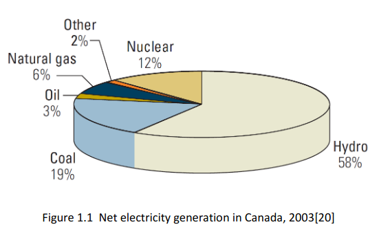 Canada sells off 30% of it’s overall electric power to the states and at any point in time may
have 6% unused.
Certain grids may experience higher
demand than is available from it’s local sources.
By taking figures listed in the petroleum journal and mapping them on to
the same pie chart shows something interesting. Non petroleum based
solutions for supplying our heating and transportation is 18%.
Another 6% (propane) might be used for heating and transportation but
clearly 76% is Petrochemical and harmful to the environment.
 Kerosine is the primary source for Air travel but the industry is starting to test solar electric jets.
Diesel and gasoline make up 58% of fuel use for transportation.
Mapping the figures from a bulletin on climate action needs substantiates the
ones from the petroleum journal showing the exact same percentages as contributing to climate change through greenhouse gas production.
Hydro, wind and solar are 100% clean, natural gas and Propane are 80% clean and nuclear would be clean if waste could be dealt with. The 3 remaining are not clean. Coal isn’t on the chart but is the most harmful of them all. Thankfully it is the least used @19%.

What this has to do with my report here-in, is a demonstrated need for efficient and economical move away from fossil fuels in favor of renewable energy to meet our transportation needs.
Entry to a New Era
Work and Home Life
As we enter a new era our lives will change. Over the next 16 years some will hope that a change in government might disrupt the plans, some will choose a new electric vehicle, some may not have the means to change. In 6 years all new vehicles must be electric. In 11 years used vehicles that are not electric can not be sold. In 16 years non-electric vehicles can not be used. These are great end
goals, but and there is always a but, what are we going to do with over 24 million plus vehicles that become obsolete? Trade-in values will drop over the next 11 years on gas and diesel models. Those that wait till 2040 will find their gas hogs are worth nothing. In some jurisdictions our political leaders want to sink more money and give more kickbacks to industries doing the polluting. They don’t want to upgrade our power grid with greener technology and tell us to
write and protest the deadlines that have been set. The EU and USA and auto makers are all planning for the demise of the ICE.
For you the public, such political parties are not your friend. Their goal is to stay in their phony-baloney jobs at your expense. If you haven’t noticed, the automakers see the writing on the wall and are eagerly turning out more and more EV versions. Personally, I
think they could do way better than they have.
Let us say you fill your 20gal gas tank $100 and can drive 600 miles or about 20 days between fills with your small car or truck. That same car or truck converted to EV using a 2 bank system and solar charging on sunny days could service your in town needs and never have to recharge. On overcast days you plug in at work or at home and replenish your battery pack in a few hours because you may
only use 16 miles of your 200 mile range. Cost to charge $0.17 x 4 x .47kw=$0.32 x 20days = $6.40 and you bank $94.00 of what you would have spent just on gas towards battery replacement. If Gcells are replaceable by owner, you just need to find the weak ones and replace them. The Gcells should last 10 to 15 years and over that time you could bank $11,280 to $16,920. You didn’t pay $38,000 to replace your car but instead paid $20,000 to convert your car and in 15 years can replace the batteries from money saved.
Maybe your needs are even milder. Maybe you just need to travel to school, shopping, rec center, etc. an even more affordable Solar EV-Trike would fit the bill $3000 with 100 mile range. And when you need to go considerable distances Your small car just needs access to
recharge every 200 miles. You may even be able to double or triple your range with more battery banks.
Recreational life
The implications on everything from backyard BBQ’s to using an RV have not been addressed by announcements. It is presumed that the clean burning propane will not end as that product is required by most RV’s for heating and cooking. The oil and gas industry is not shutting 100% down. Petrochemicals will still have a place. While I
started out as a recreational RV patron, now I live the full time RV life. This book aims to shed light on making the RV viable from a vehicle sense. Those who use the car and trailer or truck and trailer to do recreational travel will need to understand more about limits of their chosen vehicle. Considerable planning is covered in the Battery 101 chapter.
Business and Industry
Over the next 16 years businesses that do goods and services by means of transportation will need electric vehicles with range and
capacity. Charging stations will need to be placed much like we have gas stations now. Battery manufacturers will need to transition from making lead acid batteries to making Gcells too. Mechanical repair shops will focus less and less on Engine and transmission work and more on drive train (axles, brakes, rotors, wheels, tires, A/C, electrical) and battery health and replacements. Oil change and lube shops will still do lubes, but will likely transition to also do battery test and replacements. Automotive stores will carry Gcells.
Roadside service may expand to offer portable generator services (on propane) to provide charges enough for a driver to reach a charge station. Wrecked EV cars will have Motors, Inverters, charge ports, and Battery Packs removed for testing and reuse by re-builder facilities and these facilities will play a major role in converting gas and diesel cars and trucks and buses into EV vehicles. Wrecking yards for our cars and trucks will be tasked with engine removal, transmission removal, Catalytic removal for ultimate reclamation or melt down.
Where do you put all those batteries?!!
How much will they weigh?!!
Can my unit handle the weight?!!
Are all good and necessary questions.
To address these lets look at where to put them.
- In car conversion, limitations of weight and space means that in order to handle the batteries you must give up space, under the rear seat, in the trunk, under the engine compartment hood. And due to weight limits you can't have enough to go very far on a charge.
- Trucks (pick-ups, tractor trailer units) can handle more weight but still not of enough space for the batteries.
- Buses and other large frame units, have the clear advantage. The frames can handle the weight, space under the frame and where the engine used to be is ample space.
- But, and there's always a but, for our motor coach which houses all our things and is our living space how will that impact us?!!
Well as it turns out there is plenty of room, A motor to drive a unit our size is only about 15 inches long, 12 inches across and feeds a gearbox of about the same
size. The two can take the space formerly used by the drive shaft. The unit is 8 feet wide and if we take off the space used by the bins under the unit where our stuff is, and the 14 to 15 inch clearance needed by the motor, gearbox, and shortened driveshaft, we have 2 spaces 14" x by 23 inches by 120 inches. Add to this the
area where the engine was and where the fuel tank was and space should not be a problem.
Beyond just Motor, Inverter, Controller and Batteries
There are things to note about the differences between an ICE (internal combustion Engine) and an EV (Electric Vehicle):
Are the Brakes Manual, Hydraulic, Boosted hydraulic, Vacuum, Electric, Air?
Hope you planned to keep the radiator because you will need to cool the Inverter and motor.
Will your windshield washers work?
What about window defroster, cabin heat?
Emergency contingencies
Licensing, Insurance and regulations?
Brakes:
You need to be able to stop when you want. If your unit has manual brakes you are fine but I don't know of any manual braked vehicles anymore. Hydraulic too will work well but too are used more for lighter vehicles. The Boosted Hydraulic tend to use a vacuum from the ICE engine to assist in braking. You have just discarded the engine so need to find a replacement for the vacuum supply. Totally vacuum driven would presumably have a retained vacuum unit. And Air or Electric also will
work well. True you can have regenerative braking which slows the vehicle while also recharges some of the power lost from the batteries. But regenerative brakes won't slow you all that fast.
Cooling:
The motor under load gets hotter the faster you travel. Believe me you have a lot of load at 12 to 20 tonnes. The Inverter too goes through a lot of load pains as it calls for more power. The original radiator, with a fan and appropriate water pump will need to circulate water through or around both the motor and Inverter.
Wash and Wipe:
To my knowledge all vehicles use an electric pump run on demand. Likewise the wipers are already electric. Oops! That means we just found need for 12v. But being that we are making custom packs we can tap the 12v from the first 48v Gcell to supply our power.
Defrost and Heat:
While rear window defroster is electric and found on cars, and trucks, Motorhomes don't usually have a rear use window. Instead they have heated mirrors, back-up camera. We might be able to tap into the cooling line for the motor and Inverter and use a set of salvaged electric ceramic space heaters to create a means of both defrosting the windows and providing cabin heat.
In an Emergency:
What all the hoopla about in an Emergency. With a car your moving then you aren't. You may be out of gas, or crashed. Either Way you aren't going anywhere with that vehicle. It all comes in time, years ago there was a big stink about diesel which is a pressurized fuel oil, and Propane or natural gas because of how explosive they can become. Today you still can't park a natural gas or propane vehicle inside a structure, but you can park a diesel inside even though by their own admission it is a greater threat of fire.
For our lowly EV there are just too many misconceptions usually brought on those feeling threatened like auto salespersons, mechanics, people reacting to news and draw wrong conclusions.
There are hundreds of reports about cell phone batteries and computer batteries catching fire and being so dangerous because they are lithium. This is true but, and there is always a but, There are hundreds of types of lithium battery. The kinds used in cell phones are rapid charge without either of ecm (electric charge maintenance) or also known as BCM (Battery charge monitoring) and cooling. The kind used in EV must be managed by a charge system with BCM and are of a more stable form of Battery than a cell phone can have. Temperature is regulated both during charge and normal discharge.
In any accident vehicles have what is known as an inertia switch intended to cut power to the unit and diesel or propane vehicles have a master fuel shutoff as well. For those looking to convert a vehicle to EV, the powers that be have made the
following ruling, "An EV of any type must have an inertia switch that immediately cuts power to the motor in the event of a collision. There must also be a master Battery cutoff with clear notification where it is and how to access the batteries for safe disconnection".
In my design, an Inertia switch kills the power to the batteries until reset. A master shutoff is located inside the driver seat area, with notices inside and out where it is.
A secondary shutoff resides in the Electrical bay again with
appropriate notices. And each bank of Batteries will have a Bank shutoff. I tend to enclose the Banks such that no-one including me can have access to the dangerously high voltages and currents of the battery banks.
I note here that the lead acid battery is 12v @ 800 to 1500cca and it is the current value that kills. Less than 1 Amp can kill regardless of voltage. The EV banks are 384v @ 42A. There are 8 batteries called Gcells 48v @ 42A that connect in series. Nobody has a problem with the 12v Lead acid wet Battery because we know you avoid spilling acid on
yourself and don’t touch the terminals with both hands. The EV
Gcell is made of dry cells so there is no acid to spill and current much lower then a single 12v lead acid. A 65A 12v battery has a starting current of 800 to 1500 Amps. Our Gcell is 42A to 84A and surge current on a pack base of 250A.
The laws:
The legalities are changing daily it seems. As more people turn to ev-vehicles, the provinces and states are re-writing the books. As of this writing I learned that all that required in Alberta is to register the motorhome as an ev-vehicle. It licenses just in the normal sense. No change to drivers licensing rules. The insurance industry is a little behind the times. True they need to know that the ev-vehicle conversion is done right and posses no threat to people property or roadways. For this they ask you to provide a proof of compliance from a vehicle inspection outlet.
At the inspection outlet you can expect them to check things like what have you modified in the structure of the frame, axles, brakes, Emergency Brake, and how have you mounted and secured the motor. Have the battery packs been built to tight transportation safety standards. If you don't pass, expect big problems in the future. As stated above you must provide an Emergency shutoff with clear notices as to how to disconnect Batteries. And you must have an inertia switch. These things inspectors can fail you on. In our case Frames,
axles, brakes are not altered. The Motor with gearbox and shortened drive shaft will need secure mounting, and battery packs being a set size can be style can be planned for their compliance.
Before we proceed...
Years ago, cars had been around for a few decades but few could afford them. There was almost no gas stations like we have today. Frustration over stations running out of gas and lack of stations prompted many to go back to horse and buggy. Today we have the means to implement EV and in time the infrastructure will be there to make EV's as simple as gassing up your car. With EV, 15A @ 120v AC charges slow, 30A @240v AC is four times faster and quick charge stations at 360 to 480V @ 100A are few and far between but super fast. It all comes in time. LiFepo4 cells do not do well if charged too fast. a 5A
cell should not be charged higher than 5A or it will degrade and fail faster.
When I first started considering this project:
I came armed with over 40 years of Electronics experience, Computer science experience, Computer programming experience and some Power electrical experience. Still I listened to those from many walks of
life and perspectives for insight on things I may not have thought of. We are now at the point where the gearheads fought hard to discourage us from going down this path. It's plane Idiocracy
You know if there is something in my long life I have learned is that it is filled with people who can't or just won't think out of the box. I am going to quote lyrics from a Harry Chapin song here that fits the bill of my point.
The little boy went first day of school, He got some crayons and started to draw
He put colors all over the paper, For colors was what he
saw
And the teacher said.. What you doin' young man
I'm paintin' flowers he said
She said, It's not the time for art young man
And anyway flowers are green and red
There's a time for everything young man, And a way it should be done
You've got to show concern for everyone else, For you're not the only one
And she said: Flowers are red young man, Green leaves are
green
There's no need to see flowers any other way, Than the way
they always have been seen
But the little boy said: There are so many colors in the rainbow
So many colors in the morning sun, So many colors in the flower and I see every one
Well the teacher said
...
Well long story short the boy was punished and later in life he was at a new school with happy people who painted flowers in all colors and all the boy could do was gruffly say Flowers are red, green leaves are green, there is no need to see them any other way than the way they always have been seen.
Here is the point.
I understand that people who are making their living in the fossil fuel industry don't want to see anything that might take that away.
Those in product sales like Automotive sales outlets, RV sales outlets don't want a vehicle that lives forever
Mechanics and automotive parts suppliers also see the drive to go to electric vehicles as a big mistake because that will hurt their livelihood if people don't
have vehicles that will break down.
I don't think I or anybody that I ever associated with wants anybody to loose their jobs or livelihood. The same mechanics that tried to discourage me from going EV are proud of the fact that they defeated their EGR or catalytic converter to get better gas mileage or more power. Or flaunted how they add nitro to their mix to make a mean racing machine.
But I am crazy to find a way that saves money and is legal.
Should I be apologizing because...
Round trip for my gas
hog took $63 fuel before conversion but same distance after conversion will likely cost $3.60 electricity, and if the commute is a daily thing, it would cost me $7 per day towards eventual battery replacement. So instead of spending $63 for a daily trip it costs me $10.60 and half of that is put in savings.
I no longer need oil changes every 3 months or 5km
My brakes can last over 500,000 miles instead of only 20,000
My motor can go at least a million miles before I need do anything but the gas hog is going to be screaming for seals, belts, hoses, plugs, additives, and much more at least 5 times over that same period
My EV causes a little bit of carbon emissions during the generation of electricity to charge me but your gas hog creates enough deadly emissions that if you run it in an enclosed space you kill everyone in that space from
carbon monoxide poisoning.
Yes I got to go home to charge or find a charge spot elsewhere on my travels and it can take 4 to 13 hours to get charged which is different than your gas hog that can be filled up almost at any street corner. But a hundred years ago people who could afford cars had to hope their local station didn't run out of gas because stations were not that plentiful. It all takes time.
On a cold rainy day, I can drive home and plug in my motorhome go in side and stay dry. But you got a gas hog so you got to stand in the rain and get wet and cold
to serve your master "the gas hog".
It is my hope that after you read the following pages you will too see the basis for the information I have summarized.
An EV Motorhome : The Chassis
A look at the
chassis of the motorhome.
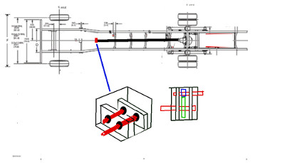
The Gulfstream-sunstream 2000 has a 34 foot long by 8 feet wide structure. To do anything meaningful one must work with facts and not rely on assumptions.
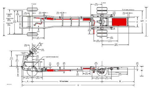 Here we have the actual specs from the F53 chassis used to make the Motorhome. Shown on the diagram is exhaust manifold, catalytic converter, muffler, exhaust pipe and fueltank. Almost all the things we will be eliminating.
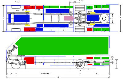
Understand these drawings are not quite to scale. Area's marked in red can't be used (propane, Gen Set, and Entry Steps, Tank dump. Ones in green are our living space and storage. Blue is possible Battery & Inverter locations and pink is motor gearbox and drive shaft. Yellow is location of leveling jacks that flip down.
Bin 7 has the spot for the Gen set. moving back is where the old hot water tank was. This can be enlarged to service the purpose of holding the Inverter and master disconnect. Bin 8 is warm storage & our instant hot water and goes all the way across to bin 2. Bin 9 is electrical and cable storage and extends across to Bin 3. Bin 10 the dump station and two tanks that go all the way across into Bin 4. Bins 11 and 12 extend across to bins 5 and 6 respectively.
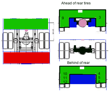
To the left (left most image) shows a topical view of bin 9 & 3 green, Rear Wheels, and Bin 10 & 4 red. The right images space available. You can see from the top and bottom images that the bins extend across but are at a reduced height over the frame. The white box shows the heating duct which cuts into the storage space & the Blue shows space available for batteries. No space can be used where the wheels are. Pink is space reserved for the motor, gear box and drive shaft.
While I'm at it, it is worth mentioning that the kickdown jacks front and rear are also going to interfere with Battery storage. In the front the jacks mount between the bins and the frame using space extending about half way back from the front of bin 1 & 7. At the rear they do the same using half the length of bin 10 & 4. The kickdown jacks are shown in yellow in the 2nd chassis drawing above. At the front they will not interfere at the back they very slightly interfere.
Using lead acid deep cycle batteries At 12v @ 62A would take 64 batteries for 384v @ 124A and result in 5440 lbs of weight to achieve 47.6Kw
of power. Using 47.6/2.166 = 22 miles and we would be 3626 lbs over weight. We have 288cu ft for batteries but only have 1844 to 2398 lbs of acceptable weight for batteries and
solar panels.

As seen to the left there are 4 basic types of battery make-up. To target 300Ah we need 750x 6A cells or 4090x 1.1A cells. During bank construction, with each cell being 3.2v, we can tap off at 12v; and 48v as we build the bank to it's 384v top voltage. We will make 2 banks switchable to make our pack for 384v @600A. I say switchable since we can run from 1 bank of 384v@300A while we solar charge the other bank. If both banks are to be charged we can't go anywhere and if both banks are fully charged
we can run from both but then will need to charge both.
The LFP-G100 has is 3.2v @ 100Ah. It is made from 18600 @ 0.8Ah cells all tied in parallel. We can use the same concept but instead of 1 x 7 x 178 cells in parallel, we can do 2 x 7 x 15 in series-parallel to have 48v @ 84A using 32700 @ 6A cells. Our Gcell mini-pack would be 10” x 10” x 12”
We wire the gcells in series and switch them to parallel to charge them. The LED lighting uses the 48v tap at 0.02A per light string. The 12v automotive systems draw about 10Ah. The computer control systems will
use a 5v DC convert from the 12.8v tap. This maximizes the charge capabilities from both 120v AC and 48v Solar DC. Finally when parked we have 120v AC @ 45A from the two stage inverter should the shore power fail.
We will be going into the batteries in depth later.
Weight distribution
The type 32700 lithium ion phosphate cell looks to be the most promising for ease of implementation, availability, price per unit and density of 6A per cell. But, and there is always a but, 3840lbs (over 1 ton) is way over the 1844lbs we have allotted for batteries. Clearly we must match available weight to the battery specs. 1844 lbs / 16 Gcells = 115.25 lbs ea. With cells at 0.32 lbs our cell count = 360.156 we use 360 since there are no fractional cells. It takes 15 cells in series for 48v so 360/15 = 24 cells in parallel. 1 Gcell = 48v @ (24*6A) = 144A. The end result is we need 16 x 144A Gcells to make 2 banks. The space required is 10” x 12” x 8*(30”) or 10”x12”x20 ft. With all things being equal, we can have 110.6KWatts with maximum range of 62.85 miles (104 km) without car in tow. We get 44 miles with car towed (75 km). Ultimately if we make Gcells 10”x12”x15” and pair them in a series/parallel fashion each gcell is 57.5 lbs 48v @72A. At this point everything is 100% balanced left to right and the frame weight class specs are ok. The majority of weight should be between the front and rear tires. Please note that this was an early spec for 72A Gcells which has been revised to 144A. Instead of 8) 10" x 12" x 15" Gcells we will go with 16) 10"x 30"x 6" for the full pack
The cockpit and everything engine compartment
Where the engine was, there is an annoying raised Cowell inside. This can be removed to make the floor flat. to improve conditions inside the coach. Making an access panel in the floor at this point would open up into a void with front axles at the front of the void and a big space between the frame all the way to the back wheels to make building the boxes and mounts easier. The floor is 34 inches from the ground but back at the bins there is only 10 inches
of clearance at the underside of the bins.
EV Motorhome : Drive Train
Drive train investigation
Let us do investigation into the motor, gearbox, Inverter, and cooling technologies. We know that work creates heat. So if we expend energy to drive a motor fast, it will heat up because it is under load. Supplying that energy is an Inverter that changes Battery power measured in DC to alternating power called AC. The inverter therefore also will be working hard.
Ultimately we want to move 10 tonnes (20000lbs) from 0 to 120kph (0 to 72mph) and we would
like to maintain this for 200kms (120miles). Unfortunately, due to weight of batteries, we have a 75 mile max range (2/3rds of desired).
The laws of motion do
not change just because we are driving the motion by a different method. So the distance traveled by the rotation of a 22" diameter tire will always be 3.14 (pi) x 22 (d) =69.08 inches until the tire wears down to it's minimum diameter of 21.21 inches which means it only travels 66.59 inches.
Mileage does not change either. There is 5280 feet in a mile and 12 inches to a foot. that's 63,360 inches to a mile. From this we can tell how many rotations of the tire are needed to cover the distance. (63,360 / 69)= 918.5. The differential uses a ratio of how many turns of the drive shaft it takes per rotation of the tire. We need to know this ratio as it will tell us how fast the gearbox output shaft must spin to make 1 rotation.
Multiply that by the number of rotations per mile and we have the first part of the equation..
From the above we now can work out rotations needed to go a specific distance and then work out the maximum time we want to take to make that distance. Our differential is 5:1 then we know the drive shaft spins 5 times to turn the wheel 1 turn and 5 x 918 = gearbox turns to
go 1 mile = 4592.75. Rotations are counted in rounds per minute (rpm). There are 60 minutes to an hour. So if we want to go 1 mile per hour, we need to divide 4593.75 by 60 minutes to get the rpm. Which in this case is 76 rpm. to do the top speed of 72mph our gearbox will be rotating the driveshaft at 76 x 72 = 5472 rpm.
With our former ICE engine it was probably rated at 1000 rpm at idle and when you tromped that accelerator down it could hit some red line at say 6000rpm. The faster you went though did not seriously increase the rpms. If you ever watched your tachometer, you would see it swing up to say 3500 then once you attained the desired speed it settled back down to say 2200rpm. I'm no ICE mechanic but to my understanding the engine had to build up the torque needed to raise the speed and once it had reached the desired speed less torque was needed to maintain it. In the days of manual gears, the engine rpm would be raised to attain the maximum speed for the lower gear then you would shift the
transmission to the next gear and keep going till you were at your speed. The automatic does the shifting for you.
So our ICE engine finally reaches 2200rpm at 72mph but from the above we know our example says 5472rpm = 72mph. this means for each ICE
rotation we need 2.49 rotations at the driveshaft. The transmission in this case would have a gear driven by the engine meshed with a gear 2.49 times smaller at the output.
Our electric motor operates slightly
different than the ICE engine. For one, it's torque is instantaneous. Speed of rotation is determined by the amount of power it receives. Like red line on the ICE motor it has a finite maximum speed of rotation. The maximum speed of rotation of an electric motor must not be above the rated speed. So if the rated speed is 1500rpm it is safe to assume that it might do 1500 for a very short time but probably
shouldn't be run continuous above 1400rpm. Our gearbox can be simple. It can actually have only two shafts each with a gear of a specific size. and for longevity we would put bearings on each shaft.
 In the gearbox shown to the left, the output shaft would need to mate with the driveshaft. Therefore the gearbox would be offset from center. Likewise the motor would be offset the other way. Where an ICE only turns one direction, an AC electric motor can be configured to turn either direction just by switching the main winding. So for
this reason there is no shifter mechanism or the gears associated with such needed.
Now for my first found specs:
Transmission ratios 1 =3.11:1, 2 = 2.22:1, 3 = 1.55:1, 4
= 1.0:1, 5 = .71:1
Rear Differential rating 4.88:1 type Dana 80
Although these specs are for a 2012 model, it gives us something to work with. The Dana 80 differential is for a vehicle with gross weight 15000 to 18000 and ours is 17500 and has a Dana 80 differential so it's safe to presume the axle ratio is 4.88:1 and my rough guess was 5:1.
So 4.88:1 on 918 to go I mile = 4479.84 rpm
driveshaft rpm @ 1mph = 74.664
At top speed of 72mph, driveshaft rpm is 5374.8rpm
At local highway speeds here of 100kph to 110kph (60mph to 66mph) we need a motor that can sustain an rpm of 4479.8 to 4927.8.
Most motors run 500 to 3500rpm as upper limits with 1500 being a go to standard. This would mean we need a gear ratio of our gearbox to be 9.855 @ 500rpm and 3.285 @ 1500rpm and 1.41 @ 3500rpm. But from the source "electric cars are for girls" they say Most AC electric motors run 230v AC @ 60 Hz and a top speed of 1750rpm. They also say that to create 230V AC from a DC source you need 340V DC from your Battery pack. Not to be thrown some curve, it's time to do more investigation. I tried to find some concrete facts about motors, torque, and weight classes
they can safely handle but none could be found. So time for different approach we will review TV programs from "Jay Leno's Garage and web cast from EV west to try and get more info.
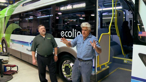
The first of Jay Leno's Garage conversion programs was about "Big Bus Conversion" featuring the California based Electric bus Troterra Ecoliner Electric Bus
In this conversion it is a ground up completely electric vehicle.
At 18000 lbs empty and 38000 lbs fully loaded with people, it has a top speed of 55mph, but due to the route and application it normally travels 9mph with many stops. So in terms of weight, It is 500 lbs heavier then our Motorhome maximum weight when it is empty. When Full of passengers, it is 1.55 times heavier than our Motohome would be when we haul a car behind our rig.
In terms of maximum speed, it can reach 55mph which is less than our desired maximum of 66mph but they say if they changed out the gearbox they could easily reach 70mph.
- In service a day less than 2 years @ 24 hours a day. Suggests it definitely is dependable
- With no tailpipe emissions, Atests to it being environmentally sound
- It uses a very unique set of completely electric components like electric hydraulic pump and air compressor, and even electric grid heating.We will need similar remedies to compensate for loss of the ICE engine
- It's about 7000 lbs less because it is a composite structure bus. So if they had gone with conventional aluminum body they would have had a empty weight of 25000 lbs. But this doesn't address the weight of their batteries.
- maintenance is virtually nil cause there is no oil to change or anything of that nature. Definitely as I expected.
Construction
- The composite material is basically fiberglass inner and outer with resin injected balsa core. It is 4 times lighter than metal and twice as strong as metal. Ours is fiberglass top half but with numerous built in walls, appliances, cabinets, etc. but does not have the rows of seats with aluminum frames
- There are no steel components to this bus except the suspension. Ours has outside steel bins front to back on both sides
- It having fully composite structure which is non-conductive makes the whole bus safe for driver, passengers and maintenance. Extremely high voltage through parts of the bus is kept away from everyone. The planning of ours also intends not to pass high voltages and currents
anywhere inside or accessible to people
Drive train
I fully grasp what they said about the EV industry going with single speed transmissions because geared transmissions just fly apart under the instant high torque of electric motors. They are using a modified 2 speed transmission so they can run low speed for route pick-up and drop off but switch to high speed going inter-route. It makes sense for their application. for the motorhome, a single speed would be more sensible. Gearing requires a auto-clutch and if you have ever had a manual clutched transmission, it is prone to damage even on ICE if not
properly clutched. I originally planned a two shaft two meshed gear transmission with engine and drive shafts offset but am now thinking to run an input shaft with large conical gear meshed with two parallel shafts conical gear at both ends and conical gear output shaft to cut torque stress by 50%
They are claiming a 200 HP Motor.
Charging
- I was surprised that they are using 12v Lead acid for internal functions. At 4 x 85lbs to run lights and accessories and running a separate inverter to recharge
the batteries adds a lot of unnecessary weight. The main drive uses Lifepo4 battery packs so switching the house batteries to match would mean they could cut weight by another 300 lbs and share the same charge system.
- Charge stations along the route charge the batteries from a gizmo mounted on the roof. A 90% charge in under 10 minutes.works for them because of the fixed route
but for the traveler, the best we can do is continuous charge from solar availability
- - In the shop is a power charger that takes an hour and they can also plug a utility charger in to charge conventionally over 8 hours. I wonder if they get a quick 1 hour charge because the batteries would seldom have much used but then they say conventional charge is 8 hours which is more feasible given Lifepo4 should never
be charged faster than a 1C rate.
Batteries
Nothing is specifically said about Batteries although they do say system runs 360v and KW of 217KW which computes to about 602Amps. Lifepo4 are standard in 100Ah, 200Ah, and 300Ah as 3.2v Gcells so the # of cells can be estimated at 2,3,or 6 parallel banks of 113 cells and a weight of 4600 lbs.
If indead they are using 3.2v @ 300Ah Gcells then they have 113 Gcells in 2 parallel banks which is great for making huge packs but not great for charging or battery replacement.
Brakes
When the foot comes off the
accelerator, the regen slows you down.
Conventional brakes 20000 miles, originally expected 100,000 because of regen but looks like it could push 500,000 miles.
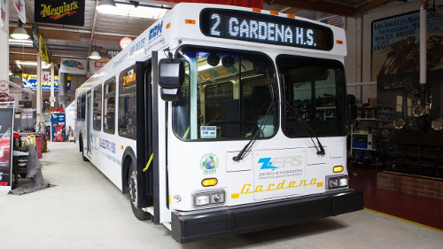 In this episode, Jay speaks with his guest about a different type of bus conversion.
For the price of the previous bus with all it's fanciness, you can convert 4 of these. 1996 new flyer bus. they buy as an old worn out bus and refurbished.
The bodies are fine but the drive train is toast so it is discarded.
These are ideal for routes of 100 miles or less
Drive train
- The motor is about 15 inches across and maybe 20 inches long and is 170 HP with about 1200 ft-lbs of torque
- It is direct gearing and NO transmission.
- Virtually no maintenance, no oil changes, fluid top ups, filters etc.
Braking
- more than double the brake life. It is full regen braking.
Batteries
- uses Lithium iron phosphate batteries.
- It has 12 Battery packs for a total of 360volts @ 213 kWh
- Recharges from 480v 100 Amp. and takes 4 hours to recharge. This I have to question after my research on batteries. Yes they can charge a 360v pack from a 480v source but the
cell charge at that rate is about 4.4v which is higher than the maximum safe rate of 4.2v cell life can be shortened by 60% at the higher voltage. Then there is the charge current at that rate of 100A they must be charging right at 1C so their batteries are being stressed all the time.
What else
- The last bus costs about 2 million dollars and this one barely costs 500,000
- The bus weights less than 18000 lbs without passengers.
EV west : Dual motor Electric drive train with powerglide
transmission. Needs fluid pump to keep clutch engaged, 54”
motor/trany and limit of 2500lbs (sub compact car)
Clearly a DC motor is not a good choice for even a car.
The TM4 direct drive motor from TMS in Quebec.
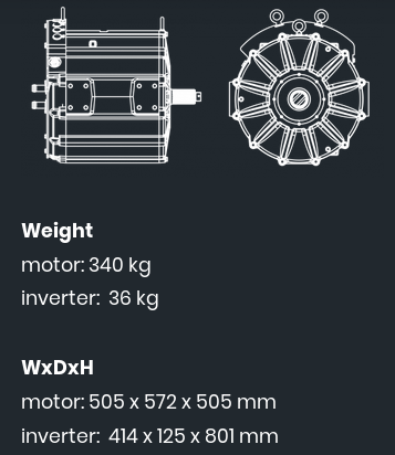
This big boy is direct drive intended for buses, trucks and heavy equipment. No Pricing but they say 200KW motor/ Inverter controller paired and capable of advanced highway speeds on heavy vehicles. They only sell to municipalities with their own maintenance shops or OEM's with full facilities. At 20" sq by 23" it is certainly a compact motor that would fit the motorhome great.
Now if we only had a conversion shop to make vehicles into EV’s.
On the bright side it does confirm what "electric cars are for girls" said about AC motors needing over 340v DC to get 230v AC for the motor. Both bus conversions talking about 360v in Battery power.
So moving on...
Realistically, 360v minimum and 300A = 108KW is minimum for my weight, 1 cu ft of battery has become 30 cu ft. And weight has gone from 517 lbs to 3960 lbs.
Without giving up precious cargo space, we have 288 cu ft so space is not a problem. Weight is another story. We recover 2035 lbs by removing the gas tank, engine, transmission , torque converter, exhaust and all
that goes along with it and emptying the fresh water and hold tanks gives us enough wiggle room of another 500 lbs. but, and there is always a but, a total of 2000 lbs less 200 lbs for motor and gearbox does not equal 3960 lbs. I am presuming that all my stuff being on board has me at maximum allowed weight. I was 800 lbs under weight the last time the unit was weighed but I have accumulated more stuff since and without unloading and / or maybe loosing the steel bins below, further weight recovery is not possible.
Working through the chapters the decision was made to lower the voltage for charge versatility only and run 2 parallel strings as banks to accomplish a boost in dependability should a cell die. This doesn't change the weight total. Set Voltage per bank at 384v made up of 8 x 48v Gcells and match the Amps in consideration of weight available. The cells are a difficult concept because it refers both to a cell being a tiny cylindrical AA type battery and also to the groups them forming the whole. It's like a
prismatic cell is made from 100's of individual AA type looking batteries also called cells.
Motors
DC Motor
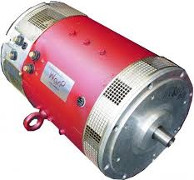 Typically run from 12v lead acid cells, it is abundantly available, low in terms of cost, and great low end torque. At higher speeds, it has virtually no acceleration. It works fine at low speed short distances but can overheat easily under heavy load, higher speeds, or long distances. The controller is simple and regulates the speed only. There is no regenerative braking (free wheels) and needs a
transmission to accomplish speed range and reverse features. Heavier motors
 AC 3 phase Motor
The go to solution for most EV conversions. Can attain higher speeds from higher voltages, Single gear ratio can do full range of motion with forward and reverse. handles higher loads with higher current packs, not near as bad heat generation, A more complex controller handles the speed and direction. Top end torque and passing power can be compensated for by the controller through a combination of voltage, frequency, and
current. Motors are far lighter and smaller. Regenerative braking is possible. Few suppliers and larger costs.
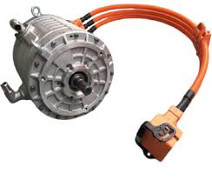 AC 3 phase OEM Motor
Hard to find except salvaged from wrecks, these are the goto for people that want to incorporate a custom solution into a similarly sized conversion. That is to say if you want to put a motor into a 3000 lb vehicle of roughly the same style as the motor from a wreck of a 3000 lb vehicle you can probably do it. The motors will be high voltage, high current, water or oil cooled, and have a special controller/inverter that checks, rotation, current draw, temperature, and other dynamics.
The one underlying thing that is emerging is that unlike ICE cars where demand for their engines is low, demand for the fuel left in the tank
is non-existent, the electrics have high demand for motors,
controllers, and Battery packs. This is because 1) they all are expensive, and 2) they last for years even decades. Being virtually a maintenance free system is quite different than their ICE counterpart which has thousands of moving wear prone parts.
The selection process
Many factors come into play in this process. Most focus on Speed, Acceleration, Distance, Charging, but those come after the computational work is done. For the motor, there are the factors of which type, how much voltage does it need, what is it's operational range (how many continuous rpms), how much current will it demand, what kind of load can it handle and for how long.
Then we have the drive coupling which can be gearbox, direct drive, transmission , and the coupling of the motor to the rear differential either directly or through a transmission/gearbox.
All this then has to be managed by the controller which must match the motor gearbox combo, and has certain demands it places on the required energy source (batteries).
Motor Starting Currents
Typically, during the initial half cycle, the inrush current is often higher than 25 times the normal full load current. After the first half-cycle the motor begins to rotate and the starting current subsides to 4 to 8 times the normal current for several seconds.
How do you calculate the maximum current of a
motor?
https://goodcalculators.com/motor-fla-calculator/
Motor Full Load Amperage Calculator
Number of Phases: 3
Motor Rated Voltage: V 230v Motor Rating: 5 hp Motor Power Factor: 0.91 Motor Efficiency: 85%
Results
Three Phase Motor Full Load Amperage (FLA): 11.96 A
Number of Phases: 3
Motor Rated Voltage: V 230v Motor Rating: 4 kw Motor Power Factor: 0.91 Motor Efficiency: 85%>
Results
Three Phase Motor Full Load Amperage (FLA): 11.03A
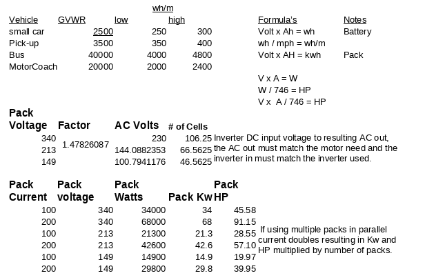
As the label suggests, wh/m is how many watts of power it takes to move a mile at a given speed.
If you use 250 wh/m @ 20mph = 250*20 = 5000w but if you use 250 wh/m @ 50mph = 250*50 = 12500w. The difference
in watts is due to higher demand.
So our 17500 lb Motorhome is going to require 1750wh/m. But it also includes air drag, rolling resistance, and towed trailers.
Cars and trucks regularly have sloped front ends to reduce drag, older motorhomes like mine and travel trailers also have such. Newer motorhomes, and transports are flat faced and this increases drag and hurts fuel economy by as much as 4mpg to
12mpg.
Inverter and controllers
An Inverter takes an Input voltage and converts that to AC 3 phase pulsed voltage. The motor you wish to drive from the inverter has to match the inverter output so to drive a 144v motor you need an inverter with 144v AC output. Likewise, a 230v AC motor requires an inverter with 230v AC output. This limits choices since Battery pack voltage = Inverter input DC and Inverter
output AC = Motor voltage.
AC Induction motor basics:
Ac motors are the most common motor used in applications because they are AC and readily available. They run quietly and run a very long time and are economical.
All AC motors have same basic components:
1. A stator
2. A rotor.
The stator is the stationary coil that creates the magnetic field. This field reacts
with the rotor bar to produce rotation. In 3 Phase, the stator sets up a current and a magnetic field. The magnetic field causes a rotation due to the 120 degree Phase offset. The current induced in the rotor sets up it's own magnetic field.
An important thing to remember about 3 Phase is they are offset 120 degrees apart and are self starting.
Slip: Slip
is the difference between syncronous speed and actual speed of the motor. Induction motors rely on the slip to induce current in the rotor and the amount of slip changes as the load on the motor changes.
In order to change the
speed of an induction motor the frequency must be changed. This is accomplished with a motor control and the most common is a variable frequency drive or VFD. Without a VFD the motor speed is fixed by the equation 120 * Frequency / number of poles.
120 * 60Hz/2 = 3600rpm
120 * 60Hz/4 = 1800rpm
120 * 10Hz/2 = 600rpm
120 * 200Hz/2 = 12000rpm
So as we see here, the VFD control part of the inverter varies the frequency. In
the first two examples there is no variance. so the motor always runs at full speed which is governed solely by the number of poles. Not what we want for an EV because we want to adjust the speed based upon the accelerator pedal.
So in the next two examples our accelerator pedal starts off at 0 and the motor is 120*0/2 = 0rpm. Then we push the accelerator down a bit and get
10Hz which spins the motor at 600rpm and we move. Then we push the pedal to the floor and the motor gets 200hz and the vehicle takes off like a rocket.
Two things things to consider is running speed and starting torque.
1. Running speed: this is determined by power supply frequency , the number of poles and the slip of the motor due to load. The specs will show the torque of the motor.
2. The starting torque is the chief limitation of the AC motor. If the motor must start with a load on consult the motor manufacturer.
Compared to single Phase motors the 3 Phase motor
has a higher power density, greater starting torque, and more
efficient than the single phase motors. They start on their
own.
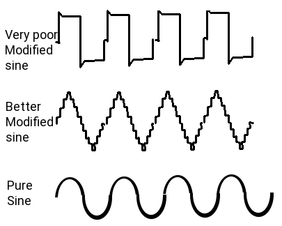 Lets add another cog in the design. We can have Modified sine wave inverter controller or we can pure sine wave inverter controller. The Modified Sine wave is cheap and does a poor job as it creates a shaky sine wave made up of almost square waves. These cause a lot of noise interference effecting everything around. The pure sine wave (like
you have in your house 120v AC lines) is a clean smooth sine wave with very little to no ripple. Pure sine wave inversion is far more expensive. Where the cheap inverter may be $30 to $90 the pure sine wave ones may be $350 to $19000. Also, the cheap one will damage any form of digital electronics like Laptops, clocks, radios, TV, and the noise harmonics can interfere with medical equipment even pace-makers!
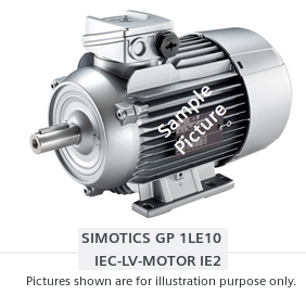
Finally,I came across Siemens Motors with a huge selection of pricey but powerful motors. At $7000 to $9000, liquid cooled, and 45kw @440v AC that's 102Ah and doable
From the research on battery packs, and high voltage and current management, I have decided to reduce the voltage of the packs to 2 banks of 384v made from eight 48v DC blocks at 300Ah. Since I have to have an inverter to drive the motor anyways, it makes more sense to run two inverters. One to PWM the 384v to drive the motor and one at 120v to 60v convert. By switching one or both banks from run mode to charge mode, we can recharge using 60v DC where a series set of 8 48v
blocks becomes 8 x 48v blocks in parallel.
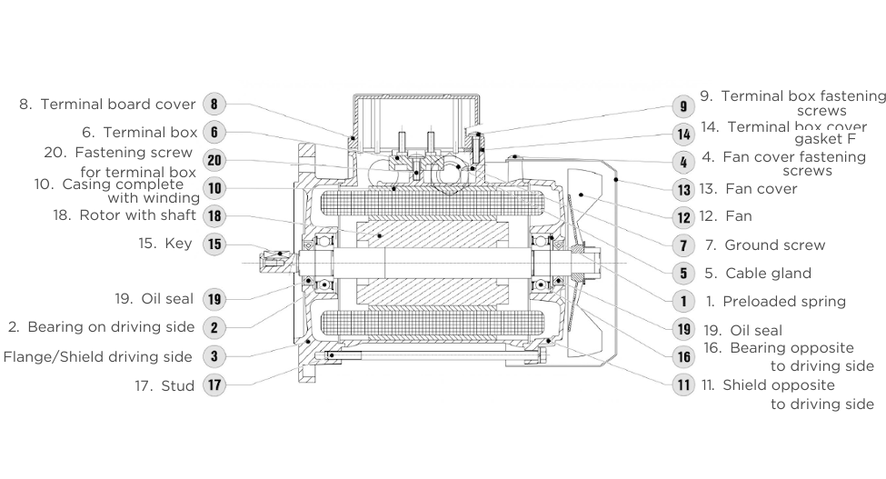
The Siemens GP 1LE10 IEC-LV-Motor 1E2 seems to be a good match with rpms from 50rpm to 5000rpm. When you get to the high voltage high current chapter you will note that when they state the current draw it is based on initial instantaneous current at point of acceleration and not the run current. If the current was the run current maximum vehicle range
at 217KW would be less than 2 miles. and we know that if we use 2.45 KWh/m which at 60mph would be 147kw in that hour. Current draw would not be 334A but in fact would be 5.56A
Motovario motors:
 This Italian company has outlets all over the world for it's high performance motors. They went to great ends to be informative about how to spec out motors for an application. No news on cost yet but they do say their motors are listed at both AC phase voltage of 230v and DC PWM or VFD at 400v. They go on to define that the same motor listed at 230v AC can be run in an automotive or assembly line framework from a DC voltage source using PWM or VFD and can do so in
both 'Y' and Delta configurations. The 'Y' configuration has a common point where all 3 windings meet and the 3 phases attach to the outer end of the windings. The delta resembles a triangle where each coil winding switches AB BC CA instead of AD BD CD.
I told you this is a big topic or maybe I'm just wordy. Then we can move on to actually doing the conversion.
EV Motorhome Drive systems
HP and Torque
Power is the rate of work and is dependent on Torque and rpm.
Torque and rpm are the measured quantities of motor output.
HP = Torque x rpm / 5252
Torque is one pound-foot and work is one foot-pound
hp = 33,000 foot-pounds per minute
100 lb-ft of torque x 2000rpm / 5252 = 38 HP
because 100 x 2000 = 200,000 / 5252 = 38
Torque is the driving force of
an electric motor not HP.
Power is dependent on the speed of
rotation
So HP is zero at 0 rpm. And varies upward as rpm
increases.
If HP =60, and Power (kw) is 45 then Torque is 91
ft-lbs @ 3450rpm and 630 ft-lbs @ 500rpm.
As soon as the motor starts to turn it produces it's maximum torque. This is opposite to how a gas motor works. it builds the torque as it's rpms rise. Thusly, for a gas motor, it needs a high HP compared to relatively low hp needed by
an electric motor.
So here is what we know in regards to the bus.
Torque vs Kw
- Torque (lb.in) = 63,025 x Power (HP) / Speed (RPM)
- Power (HP) = Torque (lb.in) x Speed (RPM) / 63,025
- Torque (N.m) = 9.5488 x Power (kW) / Speed (RPM)
- Power (kW) = Torque (N.m) x Speed (RPM) / 9.5488
- Torque ft-lb = NM * 0.73756
- Torque NM = 8.86 * in-lb
Inverters
These are work horses of the electric vehicle. The motor inverters job is to convert the supplied power from the batteries to the motor in the correct voltage, current, and frequency to drive the motor at a specific speed of rotation. The house inverters job is to convert the supplied power
into pure sine wave 60Hz at the correct current for the coach living area and it has a second part to it which must both manage selection of the shore 120v AC power, Genset AC, and Solar DC and monitors the charging system for charging the Batteries.
In our eventual system, we have several hurtles to leap. Inside the coach we must establish a selection control of which source will supply the coach 120v AC. In my original concept this was handled by the Dash computer but after careful consideration that the coach runs
when stopped and is idle when in motion, I have moved it to a
separate system. Charging was also originally in the Dash computer system but it only functions when parked and I need to redesign the system because now the Battery banks are not 1 for 384v and one for 12v but instead all are 384v DC with a 12v tap. I added roof top solar so now the coach system has to also control the solar array and implementing solar charge abilities.
On the drive line side of things, we have Battery condition monitoring and real time Battery capacity control, plus a bank switchable inverter. With the coach system being separate, we need to transfer
this state of charge info to the coach system so it can deal with charging and discharging when parked, and the coach system must report this back to the drive line computer so it can work right, Connecting by wifi from the coach Raspberry Pi to the Drive line (Dash) Raspberry Pi is one possibility
but the same can be done using a USB key moved from one computer to the other.
Inverter/Converter Tandem Units
An inverter/converter is, as the name implies, one single unit that houses both an inverter and a converter. These are the devices that are used by EVs to manage their electric drive systems. Along with a built-in charge controller, the inverter/converter supplies current
to the battery pack for recharging during regenerative braking, and it also provides electricity to the motor/generator for vehicle propulsion. EVs use relatively low-voltage DC batteries (about 210 volts) to keep the physical size down, but they also generally use highly efficient high voltage (about 650 volts) AC motor/generators. The inverter/converter unit choreographs how these divergent voltages and current types work together.
Because of the use of transformers and semiconductors (and the accompanying resistance encountered), enormous amounts of heat are emitted by these devices. Adequate cooling and ventilation are paramount to keeping the components operational. For this reason, inverter/converter installations in vehicles have their own dedicated cooling systems, complete with pumps and radiators.
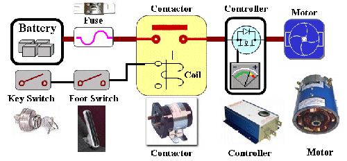 The diagram here is over simplified. It works as a working model for operation of an EV. If you used this model, yes you would have electric drive but at full speed all the time and once you are out of power everything stops. So we need to enhance the drawing.
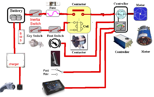
You notice it is basically the same with the missing components now shown. The Inertia Switch stops everything in the event of an accident, The BMS protects the batteries from over charge and over draw, The recharger and port to restore the batteries, Accelerator part of the pedal to regulate speed, the dash to monitor speed and results, and the forward and reverse switch to choose direction of travel.
Additional to these systems, are the automotive systems for lights, braking, a/c, radio, cooling and steering. All of
which are not shown on this depiction.
Ideally there should be cutoff switches between the battery banks.
The contactor
This a High voltage High current
solenoid. It is controlled through a low voltage side operated by the key switch/foot switch. When you press slightly on the accelerator, the switch engages and if the key is on, power flows to the controller through the contactor.
Inertia switch
Is a high current high voltage device that cuts power under abrupt impact. It must be reset for power to resume.
Main Fuse
Has to be rated for the maximum Voltage and current and is designed to blow if limits are exceeded.
Key Switch
Is the master on/off of the car.
Foot Switch Accelerator
Your dynamic speed control. The switch part enables the contactor to supply power and the Accelerator part says how much power to supply.
The Charge Port
This has both the supply lines to the charger an interlock switch to tell the charger external charge is securely attached. It is possible for there to be 2 or three charge connections depending upon design. You could have 230V AC @50A, 120 @ 30A AC, 115v @ 15A AC even some like 460V 600A.
Dash Display
Of coarse you want a fancy dash display that tells you how much charge you have, estimated distance left, Pack condition, Speed and for the hot rod types, your rpm/1000. That last item is no longer required as you aren't needing to know at what rev you need to shift. Manual transmissions are not found anymore in main stream life and EV's don't even have one most of the
time.
Controller
Ah! the heart and brains of this outfit. The controller also known as the Inverter, after the function that it does. In the realm of DC motors these do not exist. But for AC motors they are the most necessary part. Types range from the very trivial control to highly sophisticated ones. Basically, they take an input voltage range to produce an AC output range of voltage. Voltage controls the speed, well kinda. In a flat inverter it controls the speed, but in a structured inverter, changing the output frequency can also be used to increase the speed. Current from the pack of batteries provides the torque drive.
Depending on the motor chosen for a given project, it may already come with a matching controller. You can use the supplied controller if one is given, or can also design
and build your own. Most OEM's build their own to their exacting specifications. But the design of such is a monumental task involving IGBT's to control high voltages and currents, fast switching and sensing devices and the like.
BMS
Essential to the health of the batteries is the Batteries Management System. It's job is to identify cells that are not as charged as others and balance things. It looks at temperature, State of charge, amount of charge or discharge in an effort to keep all cells in prime condition.

Charger
There are a wide range chargers and charger designs. The charger must optimize the input power (AC) into (DC) known as rectifying it. Then charging the batteries from this rectified output. A good charging system will not allow the batteries to be over charged and will in fact shut off when they reach full charge. With Lithium Phosphate, you can not drain them more than 80% and can not charge more than 95%. To do so would damage the cells. Also take care considering fast charging. Charging at 4.2v per cell is typical of BMS monitored and controlled systems but, and there is always a but,
4.2v will degrade the cells life. A smart choice is to charge at a maximum of 4v which can extend a cells life by more than 25%. Current actually does the charging. If cells are rated for 1A or 6A for example they should not ever be charged faster than that. This is known as the batteries 1C rating. fast charging charges at 2C, 3C, 4C. Some liFePo4 cells can tolerate 2C but not all. Even fewer can tolerate 3C and none can tolerate 4C.
So consider this, you have a Pack that is 8 Gcells in series so you have 384v and your pack current is 600A and you are going to charge for an AC home outlet. So you have 120v @ 15A. You have an ideal Inverter charger that is very efficient and @ 384v has 5A for charging. This will do great and charge the pack over the next 5 days. Each cell is happy because it gets 0.2 amps slow charge. But you get to a fast charge station 480v 300A fast charge and give it a wirl. The on board inverter converts 480v to 384v and gives it to the batteries. The
battery packs are very angry with you. If the individual cells are 18650 they can handle 1 maybe 1.5A if they are 1.1A cells you are charging at 3C. if they 1.5A cells you are at 2C. If they are 32700 cells they are ok because they can deal with 6A.
The High voltage Inverter
The High voltage Inverter is the first stage of the drive system. It takes the 384v DC from the battery packs and feeds it using PWM or VFD to the Motor as pulses. With PWM the acceleration pedal adjusts the portion of the AC wave produced to the motor windings. So if the pedal says 5% each cycle only drives the motor for 5% of the cycle. Push harder on the accelerator to call for 50% and 50% of each cycle drives the motor. The longer the motor is getting power the faster it goes up to it's maximum full rpm. Using VFD, the pedal value is used to change the frequency from 0 to 200 Hz. The Motor normally will be rated for 50 or 60 Hz. 0 Hz = 0 rpm; 10 Hz = 1/6th of normal rpm of the motor (1500/6 = 250). 30 Hz = 1/2 normal (750 rpm). 200 Hz = 5000 rpm (Check with the manufacturer of the motor. Not many can be driven that fast.
The PWM Pure Sine Drive Inverter
The Pure sine wave inversion on the surface does a clean AC wave output to the motor. It gets it's cue from the Accelerator Potbox as to what the demanded speed of rotation is to be. It then needs to read the direction switch (FWD/REV) and use this to determine the frequency to deliver to the AC motor. IF 60Hz is the full on normal run speed of the motor at say 3500rpm, and you are asking for 200rpm then the pulse given to the motor 17% of 60
cycle per second. if I did the math right the pulse would have been .17 seconds.
The PWM Pure Sine House Inverter
For the safety of electronics inside the coach (appliance controllers, TV, Computers, Etc) we also need a Sine wave inverter when we choose to run 120v AC off the batteries. In this case, the Inverter will have 30A potential draw at a fixed 60Hz @384v. The voltage is being decreased by 3.2 and as such current goes up to 770A. Run time is 25.6 hours. We could also switch the pack into charge mode and employ solar charging. Under such conditions, our 1920A battery Pack could potentially run the 120v coach systems for 25 to 26 hours given a full charge on the batteries. The figure 1920A comes from the fact that we have a 384v @ 240A Pack made up of 8 blocks of 48v in series. When we recharge the
batteries, the 8x 48v blocks change to parallel which means 240A x 8 = 1920A. Now we can Invert 48v DC into pure sine wave AC (120v @30A) but we still get 25 to 26 hours run time.
EV Motorhome Theory wrap up
Thus far we have examined the reason for going the EV Motorohome route. I have concluded that even though I will be sinking $40,000 to $120,000 into a Motorhome that is 25 years old and was bought for under $20,000 it is a wise investment. You buy a new Motorhome and drive it off the lot and loose 30% of it's value right off. After living in for 8 months you are lucky if you get 10% of what you paid for it. During your ownership you will have paid for your lifestyle with hard cash for fuel, oil changes, typical ICE failure problems that amount to major mechanical bills,
tows, and expensive parts. In the end you spend roughly $120,000 for the vehicle, upwards of $4000 a year for upkeep, another $2000 to $6000 a year for traveling, and if you hang on to it for 5 years that's in excess of $160,000 and you might get $50,000 trade in. In the end you are out of pocket $110,000 for 5 years (22,000 a year). Your next 5 years you can expect the same. And little old me spent $20,000 for an old unit, and based upon my research spent $100,000 for conversion, spent another $500 to $1000 a year for operation if I was unlucky and was charged for power. So my first 5 years cost me $121,000 and instead of trading in I go the next 5 years for $1000. Being frugal, I put away money in the bank as if I was running a gas
hog and have $70,000 that I can use at the end of the second 5 years to replace the batteries that need replacing. Our yearly cost of ownership averaged over 10 years is $12,160 and the vehicle owes me nothing and I am debt free. You on the other hand have payments on another 120,000 plus a yearly cost of 6,000 or so.
We examined the chassis and discovered we can remove 1500 to 2000 lbs from the old ICE system. We have now got roughly 288 cu ft of space for our EV Batteries. But have a constraint on how much weight we can
add in batteries. In speaking of the batteries we have 4 basic types of battery topography that we can use. Three of the 4 topographies allow us to match and control quality of components for the highest in use life. Removing the complexity of the ICE has resulted to having a maintenance free motor good for 1 million or more miles, a traction drive inverter, a cockpit control system and a 2 Banks of batteries for which we know each and every part of the system. If a cell dies we are left with a still running vehicle but the ICE owner can have thousands of possible failure causes in his system. Check
engine light doesn't tell you much does it?
Details on our eventual cost of operation consist of campground fees which we would have to pay which ever type of vehicle our motorhome is. We might incur a charge for charging us up at the campground but can offset the charges with Solar charging when appropriate, and being able to utilize the Batteries when camping gives us the added convenience of not worrying if the power goes out. With a Gen Set running on cheaper priced propane instead of gas helps us save money there too.
Looking into our drive train we discovered that our unit is half the weight of a transit bus but similar in size, so if they can do it so can we. The
Kwh/m was determined at 1/10th the GCWR and total KW = V*A, Electric HP is much less in requirements than an ICE needs and if we prevent shortened battery life by charging at too high a voltage or current we can extend our batteries useful life.
We dove into the basic theory of AC motors and outlined how AC motors work and why they are a good choice. How to use them in a variable speed set-up rather than to just full on drive to their maximum and keep them there.
Finally, we discussed the inverters and converters that we will be needing and
constraints we need when talking about the different purposes. How the coach needs control over source selection for internal power, and charge monitoring and selection for charging. How using a single 60v battery charge source can satisfy full charging from multiple sources. In run mode the batteries configure in series rather than parallel providing for 12v systems, 5v systems, High voltage systems for drive operation and back-up 120v AC if the shore power goes out.
I think we are now ready to go to the next step and define the systems for real.
EV Motorhome Basic System
The Gulfstream motor home is divided into two parts, the existing system and the new system (inside the brown borders).
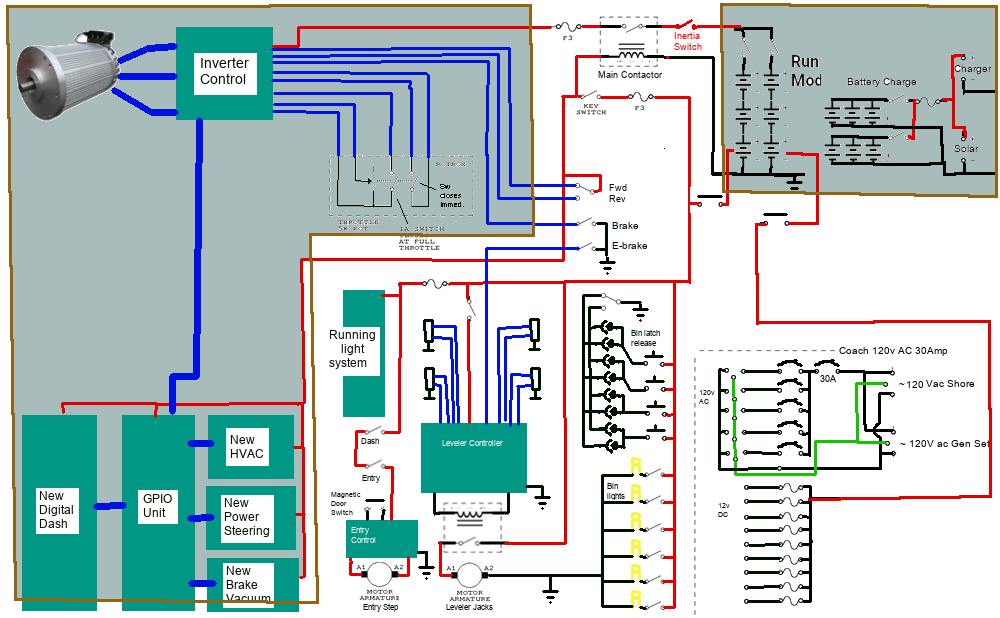
So moving left to right top to bottom we have: |
- New Drive Motor, Drive Inverter,Accelerator Pedal
***it replaces the gas ICE engine and all that went with it.
- Main contactor & inertia switch, Driver control, *New Fwd/rev switch, Brake pedals
***adding a FWD/REV switch.
- Switchable Battery Pack
***replaces the Gas fuel tank and rids me of the problems that has caused over the years.
- New 12v tap on 384v Battery *New 48v Charger, *New 480 watt 48v 10A Solar array
***means we don't need coach and chassis batteries anymore, upgrades the coach charging system, adds Solar to the system.
- *New Dash Display, computer, GPIO, HVAC, Pwr Steer, Brake vacuum
***Cockpit control system & implements replacement systems for HVAC, Steering, Brake vacuum.
- Bin Latches, Leveler control,120v AC Coach systems
***Kept as is.
|
- *New 48v Pure sine Inverter, *New Solar array drive & servos
***we can run 120v AC from our batteries & we can align our solar panels automatically to the best sunlight.
- Entry door step, running lights,bin lights
***Kept as is.
- 12v Coach system, 120v Shore and Gen Set input
***Expanded to also allow running 120v AC from Batteries.
- New GPIO and Coach Monitor computer.
***Coach computer can maintain the batteries, control the solar array, control bin heat and water management. |
As can be seen there are a lot of things built into a Motorhome that you would not have on a car. On a car type conversion you would have items 1 and 2, item 3 would be much smaller, you would have item without the solar array and have a trimed down item 5. Items 6 to 10 wouldn't be included on a car.
The Inverter control basically handles everything. In the cockpit with the driver will be the brake (and switch), E-Brake (and switch), Key switch, a Forward / Reverse switch, and the Potbox (accelerator). None of the high Voltage or High current
omes into the motorhome. The dash computer monitors everything.
EV Motorhome Convert: Cockpit and electronics
The new
Cockpit:
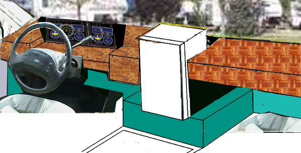 Our new concept cockpit has full width flat counter top with in dash cooler for when we are parked and entertaining. The annoying doghouse has to be removed and replaced with a flat floor access to the former Engine and Transmission cavity. This is important for access to the
EV systems which now can be accessed without the need for jacks and jack stands while we work on implementing the essentials. (the dash display/instrument package replacement) shows 2 10” touchscreen but that has been changed to one that does both functions.
Once I have the flat floor and the whole dash removed, I can rework the dash into the full flat table going all the way across the width. This was done on the right hand side in the first issue of Full Time RVer volume 1 when I replaced that side with a computer work station, and Built a cooler up front into the dash for entertaining. Now we
will be doing the drivers area.
In an earlier Issue I tried to rework the dash for a conventional ICE engine, and was successful to a point. I had remade the dash as a flat table with a custom instrument cluster and had all the switches,
heater control, radio system all configured to work. It had a fold up top which improved access but, and there is always a but, it still had hundreds of wires for features the unit did not have and now is not in keeping with a full on EV design.
The mock-up picture at the top of the page gives the basic idea. We want a flat table with a recessed EV instrument and control cluster. We will lose the radio, heater and switches as all this is now available
from the displays. Essentially, the entire Dash instrument cluster can be run and tested as a self contained system. Under the counter top which will lift up for access we will have the simple wiring to the ebrake, brake, and canopy controller and the wipe/wash controller. We will replace the accelerator with a pot-box foot operated potentiometer. We lose hundreds of wires to give a nice clean and clear compartment. So for starters we will build the Dash instrument cluster as follows:
Digital Dash
We want to make a New Digital Dash for a vehicle. So what sort of things should this Dash have. For ease of viewing it should have at least a 10" HDMI displays and full computer control. Obviously it needs to have adjustable brightness for bright daylight and dark night
driving. Being a 10" display it will be 8" wide and 6" tall and sit back from the driver. It should control most if not all driving seat adjustments, so it needs Radio control with volume, station, and balance, Heating and A/C adjustment, Mirror adjustment, Pre driving system checks, Back-up camera with rear view capability, possibly a front view dash cam, and be fully Electric Vehicle capable. Optional would be GPS navigation, Bluetooth connectivity for hands free phone use. That's a pretty tall order but lets see what we can do.
Choosing to have full computer control is most likely to use a Raspberry Pi 3b+ as it has a lot of functionality and is small (credit card sized). Our Pi computer would mount to the back of the displays and light sensors mounted into the frame surrounding the displays would
give us the ability to control display brightness automatically. Forward facing dash cam is no problem as it can mount to the back and plug conveniently into the Raspberry Pi. The display has two sides on the left is driving functions and at the right is feature control.
I2C is a two wire communication protocol that can access and control roughly 128 devices with many of them handling many different functions. Now we will look at how we can implement all the features by the PI computer.
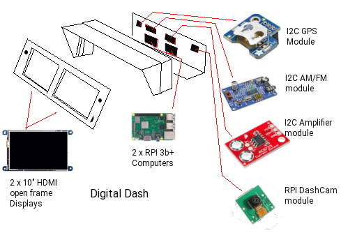
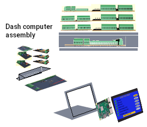
My original plan had 2 10” displays, 2 Raspberry Pi3b computers, GPS, Radio, Amplifier, Dashcam modules.
The new display unit to the right is 10” x 8” x 6” and has the computer mounted to the display, all the input and output boards positioned behind the display and the modules placed along the back as before but the whole control system is self contained and moveable to any vehicle. There is 1 ADC module, 2 input boards and 3 output boards that handle any size and configuration of vehicle. Lighting, and items in the canopy wire to a canopy control board which also
serves as the fuse box and main distribution center.
Wiring and feature pre planning
The concept here is to have an all purpose universal automotive controller and computer that can accommodate all vehicle classes from the sub-compact to the large scenic cruiser buses and Motor homes. To accomplish this the dash display has a credit card sized computer on it's back and this computer wires to a base board just behind it. The
function of the base board is to supply power to the function boards, pass information to and from the computer to the various function boards, link the radio, GPS and phone into the system, and establish charge/discharge monitoring. Above the base board is 3 output modules, 2 input modules, and one analog module.
Lets start with the Raspberry Pi 3b computer. It has a 40 pin GPIO connector and we have 16 connections from the computer in use. The 16 wires pass to the 16 pin computer connector on the base board. 4 of the 16 wires supply the power, 2 operate as an I2C communication to the function boards. 4 supply notification of input changes, one
supplies real time speed of motion changes, and 4 are informing the computer about battery discharge and charge status.
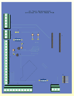
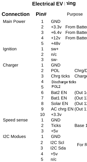

This was the original base board design which didn't have power lock-on and alot of wasted space. The new is 1/4 the size. Now on the base board we have a power connector, followed by an ignition switch connector. The ignition switch turns on the system and once started it cannot be shut down until the computer says it's OK. Next we have the charge controller connector that wires to the rear charge port. Then we have a speed sensor connection. The speed sensor wires to a magnetic or optic sensor on the motor shaft. An I2C connector
connects to 3 modules for radio, GPS, and Phone. Lastly, there are two connectors to the feature boards. One is 11 pins and handles all inputs to the system, the other handles all outputs and is 14 pins.
I list the connector pins and then show the 3D view of the original board.
There are 3 output modules that are at
addresses 0x20,0x21,and 0x22. There are 2 x 8bit channels per module.
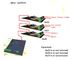
Board one is GPIO1 with channel A being mirror control and channel B being window control. Where there are provisions for two mirrors, there is provisions for left/Right front and left/right rear windows. In a car or truck application 4 window controls is posible but in a motorhome only one is required.
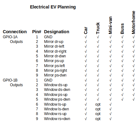

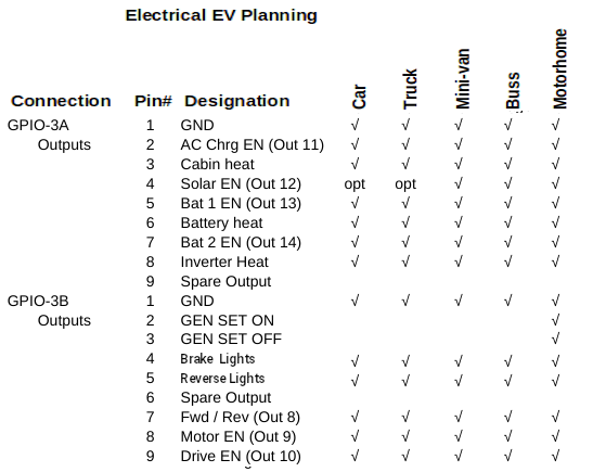
The second module mounts on top of first one and except for address is identical to the first. You will note that depending on the vehicle class not all bits in the channels are used. Channel one handles fan speed, defrost, AC, turning on/off the lights and in the case of motor home the leveling jack power. The second channel controls the rad fan, and rad bypass to help control motor cooling, more lights,
and in the case of a motor home, the entry step.
The last output module again is at a different address but this time has marks like (Out 11) that identify output states that either go to the ADC board for motor control or to the base board for charge control. Channel A handles charge Enables and cabin, battery, and Inverter heating (for cold weather). Channel B has provision for a Gen Set on a motor home, and motor related Enables. and that's it for outputs.
Drive-En has special meaning. First this signal in software prepares the vehicle to be driven. The control signal passes to the traction inverter to turn it on and it also enables the brake vacuum pump, power steering pump and h20 pumps so they are ready as soon as there is a call to move the vehicle.
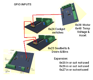
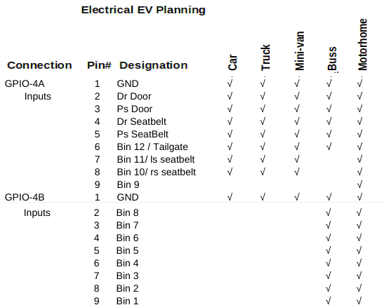 Board 4 starts the input side of things. Channel A informs the computer of the status of doors, seat belts and bin doors. Channel B deals entirely with bin doors. Note that channel B is only used on Buses and Motorhomes. Depending on the type of vehicle channel A differs in meanings.
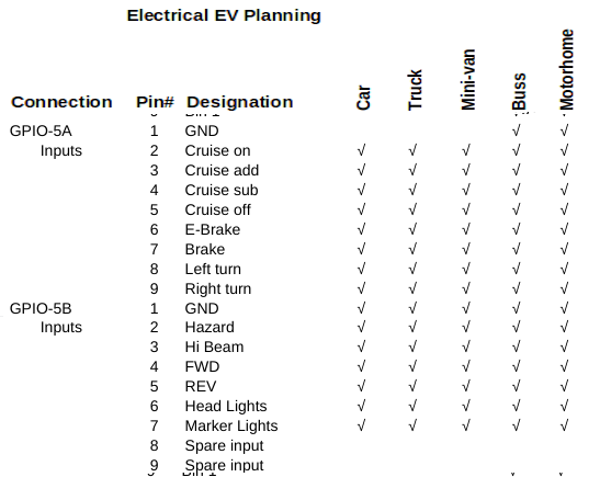 Board 5 is the last input board in terms of digital inputs. It wires to the cockpit switches for Cruise, brake and E-Brake, left turn, right turn, Hazard, hi-beam, headlight, marker lights, and the fwd or reverse switches.
The computer monitors the status of the physucal switches as well as the touch screan versions and uses the physical switches with maximum priority. For example, if the healight switch is on or signal left or right is on or hazard flash is on using real switches then the computer takes then as true. If they are off, the touch screen can be used to turn them on or off, but if they are on by touch screen action and then you use the physical switches then the computer follows the physical state.

The final module is the ADC module which reads the accelerator pedal, the battery voltage and the temps on one side and controls the motor Inverter on the other side. When you depress the accelerator pedal the computer notes the value read in .1 miles per hour increments. If you haven't turned the cruise on it passes the value to the traction drive output which attempts to move you in the direction you have set. If while in motion you select cruise on it sets the last speed request as a preset and sends that instead to the traction drive ignoring the accelerator. A touch of the brake or use of cruise off shuts off the cruise feature.
Production models of the universal digital dash would use SMT's for a tiny compact design.
Canopy Systems
The cooling, steering, braking
systems and lighting management resides up front in the canopy along with the Motor and Inverter control. As designed, we have Motor Control (Drive-En, Motor-En, RPM value) coming from the ADC board. We also monitor Inverter and Motor temp from the ADC board. We can control the Rad fan and Rad bypass using GPIO-2 outputs and can also heat the Inverter and Motor using GPIO-3 outputs. The base PCB collects rpm ticks from the sensor on the motor shaft.
GPIO-2 supplies Left-turn, Right-turn, Markers, headlight, Hi-Beam, and Fog lights. These signals are designed to operate 48v 0.02A LED light systems. If the plan is to use 12v incadencent bulbs, 10A relays will be needed. The steering pump, brake vacuum pump and water pump must connect to 12v using Drive-En signal so that operation is on when intending to move the vehicle. The headlight and high beam must use a relay. If motorhome application, the leveler output also needs a relay for the leveler pump. The Brake lights and reverse lights and trailer lights, while not part of the canopy systems will be in the canopy. We added an output to the above specs for sending signals to turn on and off brake lights and reverse lights. In an ICE design water, brake vacuum, and pwr steering are the result of the Engine
running and in our case will be the result of Drive-En signal since the motor only turns when moving.
Cockpit Systems
In the cockpit with the driver will be the brake (and switch), E-Brake (and switch), Key switch, a Forward / Reverse switch, and the Potbox
(accelerator). None of the high Voltage or High current comes into the vehicle. The dash computer monitors everything. The ignition is locked to on even if the key is removed. If an incorrect password is entered 3 times the computer will issue a shutdown. If the vehicle is in park and the operator selects shutdown it will also shutdown. We need to lock the ignition on until the computer says it's ok to turn off the system. At back we have charge control and Batteries and on the roof the solar arrays.
Here to we need more signals. To charge the 48v battery blocks we have a Charge-En but now also need an auto switchover
circuit.
Items not yet incorporated in the design include keyless entry, cylon eye and electric door locks. Keyless entry and door locks will not be incorporated. Keyless entry needs the computer to be on 24/7 which is a power drain. Adding door locks requires an additional 2 to 4 signals. The cylon roaming eye is a novelty add-on. An anti-theft
security system also would need to be an independent Add-on since we don't want to drain our batteries needlessly.
In an ICE the PCM (power control module) runs from the 12v battery 24/7 and typically draws 0.2 to 0.5 amps continuously. This has been a problem for years as a 65Ah battery with this constant drain can be depleted in as little as 130 hours of not being started. The PCM handles locking doors, unlocking doors, keyless entry, courtesy lights, and security systems. Being an EV we also have a problem
since we can't start the vehicle to recharge the battery we would need to charge from solar or some land based power outlet.
Universal EV conversion
In the Dash display screens the type vehicle the system is set up for is shown above the speed

 depending on the type of vehicle.
Lets take a look at it from an
operators standpoint. We need to know our speed and whether it is Kph or Mph. The old way was to have a cable from the transmission to the speedometer. The speedometer updated a mechanical odometer in Mph only. A moving needle rotated around to point to tiny numbers. Newer versions used a sensor and moving coil meter in much the same way. And the newest of vehicles have custom dash with speed readout and digital odometer.
Our dash display is a 10 inch touch screen. In the center is a speed readout with numbers around the perimeter. As speed increases the number background turns from Grey to green. two buttons below the speedo select Kph or Mph and automatically adjust the speed numbers and readout to match.
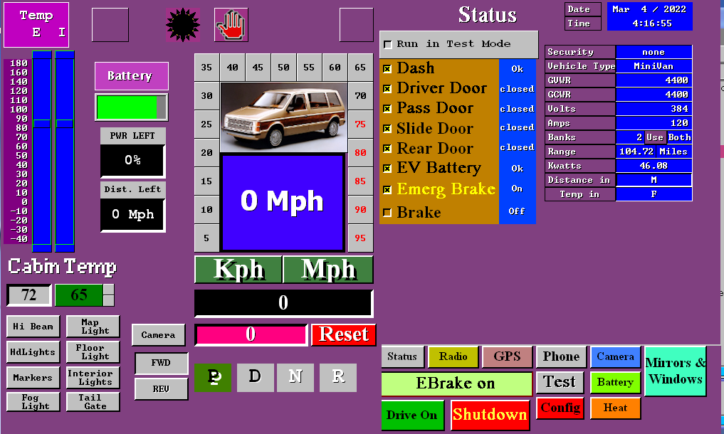 Above the speedo is left turn and right turn indicators and the current state of the headlights (on/off/hbeam) and whether cruise is on or off. A Trip odometer and trip reset is below the odometer. Being an electric Vehicle we don't use a gear shift we use a fwd/rev switch. It's all Electronic. When Ebrake is ON you are in Park. When off you
are in neutral. When stopped you can use either the switch or the touch screen to switch from FWD or REV. Being an EV means we need to know the state of the Battery and the Inverter temps and Motor temps. Top left shows this. Under that is the current cabin temp and desired cabin temp. And below that we have buttons to control lights using the touch screen.
To the right is the main menu. It allows you to select different features using the buttons at the bottom, Right now the status display is showing results of the system test. It verifies that it is OK to use the
vehicle. One might ask why do we need to verify it is OK to use the vehicle. The answer is simple. The system checks that the dash control system is working, Seat belts are buckled, and the doors closed and eBrake applied before it will allow the motor to function. It is more informative than a check engine light and buzzers. Later you will see how it plays into doing self repairs. For now let's assume it all is OK and so we select Drive On.
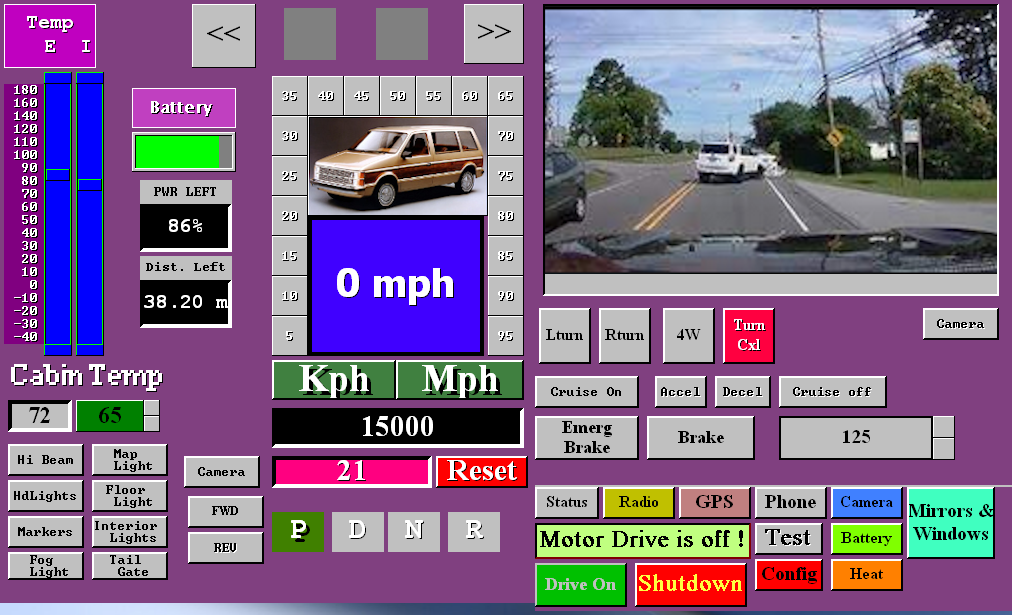 The right side changes to the drive screen. At the top is the Dash cam/Backup cam display. Using the Camera button below the display you can view the Dash cam/Backup cam/Info displays. There are also touch buttons to turn on or off Turn signals, Hazard flash, Brakes, and Cruise control. While you still have all these in the car, you may use either the car provided ones or the touch screen ones. In test mode, you can use the Accelerator at the bottom without actually operating the motor.
There is a Credit card sized computer on the back of the 10 inch Display. It costs an amazing $45 or less and is the heart and brains of the Vehicle. It takes automotive controls and user actions to control the whole vehicle through a simple single board controller I have designed. But more on that later.
Power first. We need a Battery system that has a certain voltage, specific Amp capacity, which based upon the formula V*A=W we can determine watts of the battery. Using the GVWR or GCWR we can determine the distance we can go. W/1000 = kw, and GVWR/10000 = kWh or kilowatts to move a weight per hour on flat even ground. For my Motor home it was 17500lbs/10000 = 1.75kwh per mile. To deal in KMs take 20*m/12=km.
So for my Motor home I planned 2 banks of battery at 384v @300A = 115,200w = 115.2kw per bank. 2 * 115.2 = 230.4kw and so @ 1.75kwh/m I should be able to go 131.65 miles. I used 2 banks because if a bank goes bad you need the ability to keep running and 2 bank @300A = 600A and each bank is lighter. 1 bank @600A is very heavy.
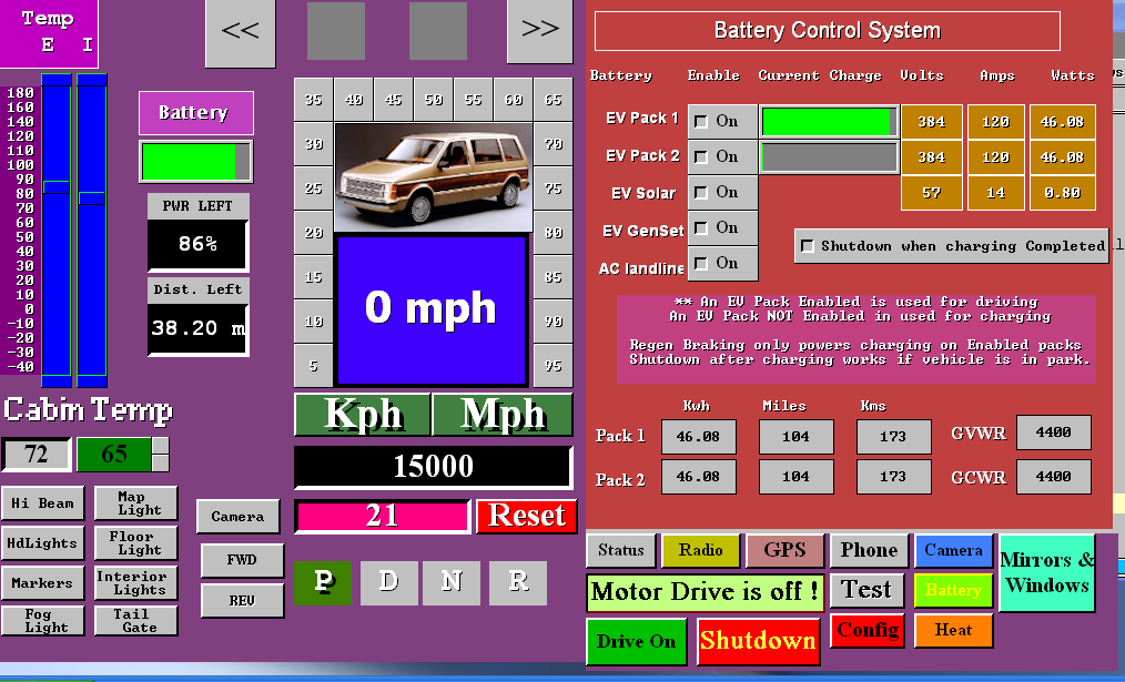 Charge in and out of the battery is
measured in coulombs. 3600coulombs = 1A. So the computer reads the amps per second going into the battery or out of the battery system. It can update in real time the amount of battery left and how much farther you can go. Solar panels on the roof charge the system when there is enough sunlight. The Motor home it has 57v @ 19Ah charge. This means an Empty
battery pack would take 31 hours. But and there is always a but, both have onboard charging from standard house current so from 120vAC @ 15A = 37A so the Motor home improves to 16.18 hours. Changing the charger to run from 230vAC cuts the charge time in half. Tesla charge stations are rapid but risk charging so fast that the batteries can become stressed and fail early.
Not to fret, most people travel less than 50km in a day and if we go with figures used by the insurance bureaus to compute insurance, 20,000km/y = 54km/day = 33m/day = 40% use or 2.5 hours charge time
needed per day.
For the battery screen we can use battery pack 1 or 2 or both for use in driving. If not using both, the non-enabled one can be solar charged while you
drive. Enabling solar charge works if there is enough sunlight. On a motor home you also have the option to charge from a Genset. And of course there is 120v AC charge when parked. Selecting shutdown when charging is complete only works on a parked vehicle so you can set to charge while your shopping or at work and the system will shutdown unattended. Ideally, you would disable both batteries for driving and
choose Shutdown when complete which disables all vehicle operations during the charge cycle. The values shown on the screen actually come from the config screen. They change as conditions change.
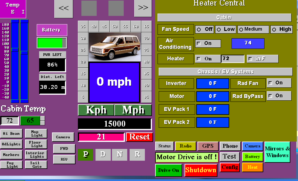 Next up is the heater control screen. It allows changing for comfort and checking on the health of systems.
Comfort wise you can set fan speed, AC on or off set your desired temperature and choose between degrees in C or F. You can view the temps in the battery packs, motor, inverter. In cold weather the EV systems need heat for optimum functionality until their self generated heat gets too hot then the cooling systems come on to cool them down until they reach minimum ideal temperature.
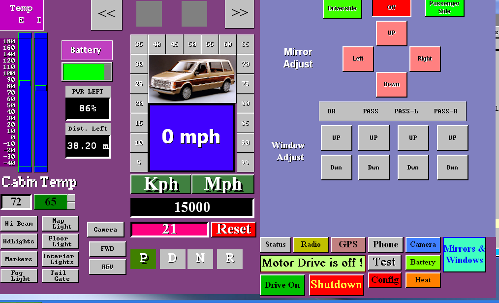 Self
explanatory here. You press a button to move the mirror to the
desired state. Likewise you can open and close 4 different windows.
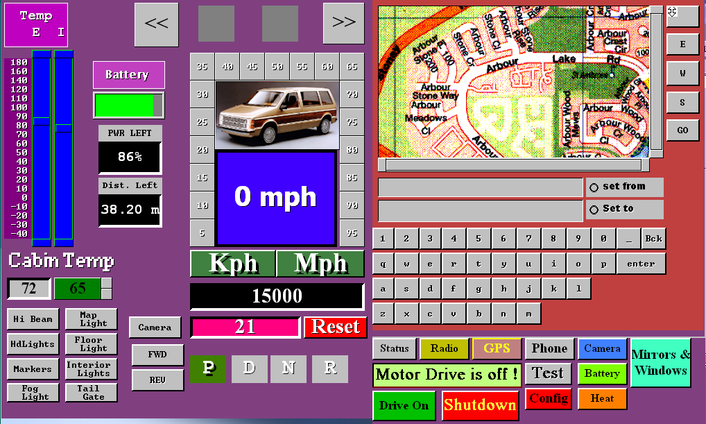 Here is a computer control of a Navcon GPS system at the top is the selected road map with map adjustment below. Under that is where you state your starting address and ending address using the provided keys at the bottom. The map shows your st art point and end point when your current position allows them to show. Your current position always shows center unless you slide the map using N E W S keys.
 No presumption about there being a radio or not. Using a built in radio module and amplifier operated by this touch screen display, all you add is speakers which usually exist in any donor car being converted.
 Imagine if you will, on your current vehicle, you have a check engine light, battery/alternator light, temperature light and sometimes a little door open indicator. If something goes wrong you need to go to a
garage and pay for them to use a OBDCII to read cryptic error codes and reset them after fixing the problem.
This EV Dash has built in TEST and Report facility. The report facility just tells what the current detected states are. The Test facility here allows you to see 10 categories on the left with currently the window up/down set showing. It is a work in progress as I refine software to match the actual electronics.
By turning on and off the checkboxes you can confirm that the desired action is being done like moving the mirror left or right or up or down. Turning on or off the park lights, headlights, or seeing that when you press on the brake pedal the automotive control boards sees it. You are having trouble with cruise coming on when you ask for it. So you come here select CTRL (control) and see if the cruise on indicator is on or off. Press
Cruise on the steering wheel and see if it shows you pressed the button. If there was nothing happening, check the other cruise related buttons or turn signals or hazard and if they are all dead the cable is likely unplugged. If only one is not working it is likely a broken wire or bad switch.
 Then we have the camera screen to be used only when stopped. If you want to use it while driving, you can’t because that is a huge safety issue.
 Two more screens are present but not yet functioning.
One is the phone and the other is the Config screen.
The phone would connect to your phone by bluetouth and
config allows all the presets to be set.
Electrical Systems
The electrical systems of an EV conversion encompass several interconnected things. At the helm is the computer controller which in this case is a Raspberry Pi 3b credit card sized computer. This computer connects by 16 wires to a base PCB. The base PCB also obtains power from the battery packs, and has connections for ignition switch, charge control, RPM tick sensor, I2C accessories, and the input, output, and ADC bits arrays. There is an on board I2C level shifter for communication. The inputs and ADC
bits are provided on a 11 pin header and the outputs on a 14 pin header. As such the first part of the system is the computer and the base distribution system.
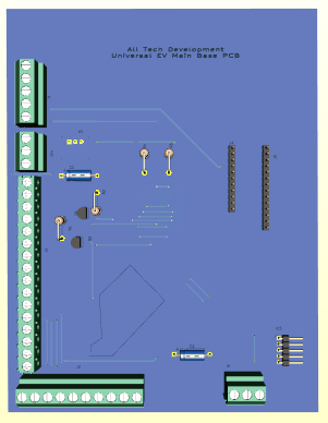
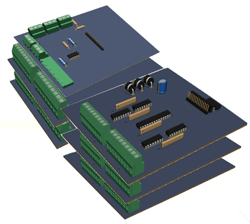 To the left is the base PCB and next to that is the input / output modules that sit above the base.
There are two input modules and the ADC module in the first stack and three output modules in the second stack. All connections to the modules are at the face edge to the automotive functions they go to. Two headers are on each of these boards. One goes to the previous board and one to the next. So base 11pin connects to input board 1. Input board 1 (second connector) goes to board 2. Board 2 (second connector) goes to ADC board. On the output boards they inter-connect in a similar fashion.
In such a manor, we can have the entire electronics distribution system in a box about 9" x 6" x 4.5". This makes up the second part of the system. In the engine canopy we have canopy controller, and sense pass through. The Charge controller mounted at the back of the vehicle which manages 120 AC charge and Solar charge, and finally the batteries with BMS and switching charge control. The Motor, PWM inverter is in the canopy for cars, and trucks and motorhomes have these back at the differential,
Raspberry Pi 3b computer
This tiny but powerful little
computer has 4 usb 2.0, I2C, SPI, RxTx communication, Ethernet, a 40pin GPIO connection and HDMI is where we will be most concerned with.

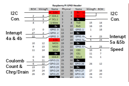
Because we added 2 banks of battery, we needed to add a second set of Coulomb Count & Chrg/Drain leaving just 5 GPIO unassigned. A front facing CCM camera connects to the CCM port to provide a dashcam and the rear backup camera talks by bluetooth or wifi.
The Raspberry Pi 3b 40 pin GPIO connector is a very powerful tool in my design. While not all the pins can be used and several are duplicates, there are 17 available and we are only using 7 to 9. The breakdown is as follows
- 1,17 = +3.3v
- 2,4 = +5v
- 5,9,14,20,25,30,34,39 = GND
- 3,5,27,28 = I2C#1 &
I2C#2 we are using only I2C#1 @ 3,5
- 7,19,21,23,24,26 = SPI1 & SPI2
- 13,15 = int4a int4b
- 16,18 = int5a int5b
- 22 = rpm sense
- 29,31 = charge / discharge counting
- 8,10 = Rxd Txd
- 11,12,32,35,36,37,38,40 = GPIO unused
The RPI is powered by the Base PCB that is handling all
comunication to the various systems. I2C provides communication to the various systems with pins 13, 15, 16, 18, 22, 29 used as
interupts for input changes (int4a int4b int5a int5b), rpm sense, and charge/discharge ticks. pin 31 tells the direction (+)=charge (-)=discharge. During programming the EV system the first of 4 USB ports attaches a keyboard. A second USB port is used for the back camera recording to a flash drive. The HDMI attaches to the display and a 3rd USB provides touch screen functionality. The Dash Cam connects to the CCM camera connection. The rear camera is still being worked on.
Base module
Observing the images below, we can see the base top view, left edge view, and front edge view. Left side back is the power connection with GND, +3.2v, +6.4v, +12v, and +48v. Moving forward we have the ignition switch which turns on the whole system. Ideally the ignition once activated only turns off under computer control. If shut off before the vehicle is safe to shut down, it holds power on until given a shutdown command. Our next connection goes to the Raspberry Pi 3b computer. The last view has the charge controller connector and the RPM sense. Far right is the
I2C carry on connector pointing off the right side. This connector is used to add GPS, Bluetooth, and AM/FM Radio to the system.

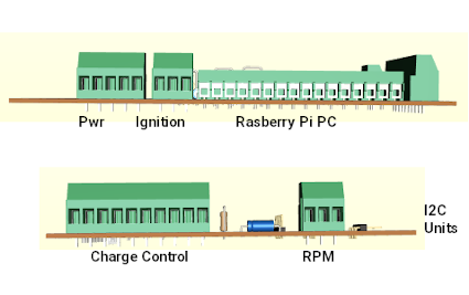
 PCB prints and schematics are available in a separate service
booklet.
GPIO - INPUT
modules
The input modules have 16 inputs per module. The first module is at 0x23 and the second one is at 0x24. Each module has a single mcp23017 GPIO-expander chip, with selectable addressing. All connectors have pin 1 designated as the ground pin. The Input boards have a 4 pin
connection on the side that provides GND, +5v, +12v, and +48v just in case the need arises. The first input module (0x23) handles seatbelts, doors, and bins. If a door or bin is open that input is grounded. If a seatbelt is unbuckled it is also grounded.
The second input board connects to the steering wheel cruise control switches, the E-Brake switch, the Brake switch, the left turn, right turn, hazard switches on the column, hbeam, Fwd, Rev, headlight and marker light switches. The switches are actually repurposed to simply
toggle between +5v (off) and Ground (on) to tell the computer what the operator has selected. The output board does the actual activating of the feature based upon user manual controls or touch screen selected operation.


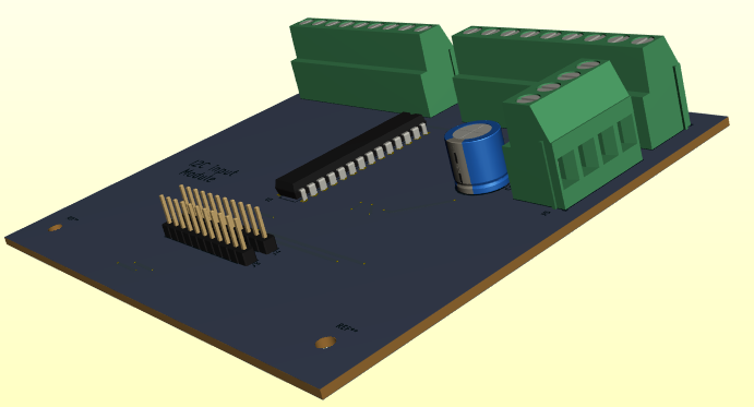
ADC module
The top board on the first stack handles ADC operations. These operations are handled by two IC's. Address 0x28 is the accelerator output to the Motor controller. and address 0x48 is the one that reads the Battery voltage level, Temperatures of the motor, the Inverter, the Batteries, and the cabin. It also reads the accelerator pedal. This gives the computer the means to have both manual and cruise control, and keep the operator informed of the temperatures, and charge state in real time.
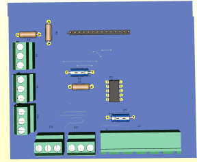
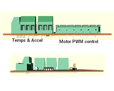
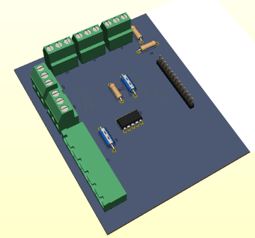
A DS3502 (0x28 address) 7bit digital potentiometer presents the desired speed value to the motor controller. This value is either the value obtained from the accelerator pedal reading or the value set when
cruise is enabled. Let us say that 5000 rpm is full speed from the motor and results in 66mph. This potentiometer has 128 increments so when the value is 0 (the first increment), motor rpm = 0 and speed = 0mph. When the value increases to 1, rpm increases to 62.5rpm and speed = 0.51mph. This is of course governed by 3 factors provided by the computer. These factors are DriveEn which powers up the Inverter, MotorEn which allows the motor drive to function, and lastly Fwd/Rev which determines whether to move forward or reverse.
The ADS7830 8 channel Analog to digital converter, supplies the computer with the battery voltage in the range of 336v to 384v, 4 Temperatures in the range of -60 to 200 degrees F for Motor, Battery, Cabin,
Inverter and the read accelerator value 0v to 5v. Each value is in 1024 increments such that battery voltage is in 0.375v increments, Temperatures are in 0.2539 degrees F, and accelerator is 0.00488v = 1/8th of 0.51mph per increment. The computer basically just divides the accelerator value by 8 such that any value below 0.039 = 0.
GPIO - Output modules
The output modules are far more complex than the input modules. While they still use the mcp23017 chip, with collectible address 0x20, 0x21, and 0x22, they also have optic isolators and pull-up resistors. The expander chips have limited ability to drive heavy loads so the isolators provide both heavy load capability and increased voltage to feature capability.
For example, the automotive
mirror up-dwn-lft-rght motors run when 12v is across the windings. The computer commands using 0v or 5v which won't do. So the opto isolator allows the computer to control using 0-5v and the opto drive to use 0-12v. In essence, we get control using solid state rather than relay driven circuits.
So board 1 is Mirror and Windows. Board 2 is climate control, leveling, and lights. Board 3 is Generator, Drive heating, charging and enabling. There is provision on the board for running the interior fan at 3 speeds for board 2. For board 3 there is provision for a DIP switch to pass Enable signals back to the Base board and subsequently
the computer. A Mini-Van doesn't use all the outputs. They are there for the Motorhome which needs Leveler control, Entry Step extend and retract, generator start/stop, and so forth. I suppose a mini-van with a handi-cap Entry Platform could use the leveler or entry step to extend or retract a ramp or lift.
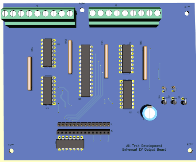
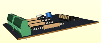
The output boards are 5.2" wide and 4.4" deep. As it stands, the use of LED lights for markers, brakes, reverse, and signals can be easily accommodated without extra provisions. Headlights are the ones that will need an extra relay. Interior lights, fog lights, maps lights and floor lights can also be LED so don't pose a problem.
EV Connections
Starting with the Dash, Remove the instrument cluster and modify the dash for the 10" HDMI touch display. Mount the raspberry pi computer to the back of the display. Connect the HDMI cable to the display and raspberry PI. Locate and wire the ignition switch to the base PCB and connect the cable from the raspberry pi 40 pin connector to the base pcb. At this point supplying 9.6v of power to the power connector will allow programming the raspberry pi and testing the raspberry pi comes on with the
ignition switch.
Connect input boards and output boards as indicated. The whole system can be tested at this point. You are looking for input changes to cause interrupts
and touch screen actions like turning on and off lights, fan, AC, etc. to result in output state changes. For example see if a pulse shows at the window up/dwn when you try to open or close a window.
My intended frame work consists of 'L' shaped frame that the display mounts to with the raspberry Pi mounted to the back of the display. The base PCB mounts to the flat part of the frame and connects to the raspberry Pi 40 pin connector. A 'Z' style frame mounts to the back of the first frame such that the input and output boards can mount to it. At this point you need to decide if you want connections to face back or forward and mount the boards. The two ribbon cables from the base PCB need to feed from behind the Z-frame if the i/o connections face forward, or can pass
to the boards from the front if connections face the rear of the assembly.


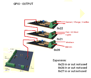
 There are 110 wire connections going to the various systems of the EVehicle from the input and output boards. My preference is to wire from the boards to a plate with barrier strips on it organized into purposes. Like put two five contact barriers. Wire the 9 pin mirror wires two the two barriers. Now two cables of 5 wires can go to the drivers
door and passenger door to connect the mirrors. The same goes for window up and down. Use four three contact barriers supplied by the 9 pin window connector. A 16 contact barrier will suffice for the seat/door/bin inputs.
Systems after this point at not in the cockpit they reside in the canopy, back of vehicle or at various light
sockets
EV Charger
The charge controller takes
direction from the dash computer and the AC charge port. The computer provides 4 enables (battery pack 1, battery pack 2, Solar, and AC charge). At the AC charge port there is a microswitch that is activated by inserting the plug into the port. When AC shore power is plugged in, it converts 120v AC to 60v AC and if the computer has issued a 'charge-enable' signal passes that AC voltage on to a full wave bridge rectifier to produce 57v DC for charging. As long as the AC charge cable is plugged in normal vehicle operation is prohibited.
Roof top solar panels supply
power when there is sufficient sunlight also to the charging system. It can also be enabled/disabled from the computer. The 2 battery pack enables determine which battery pack(s) to use.
It has two coulomb counters. One
monitors charging at 57v and the other monitors 384v discharging and regen charging. The charger also handles switchng 48v blocks into series for run mode and parallel for charge mode.
Engine
compartment (Canopy):
We don't have a clunky engine and transmission so what we are left with are, a wire cable from the battery 384v supply, and a lighter power cable with +48v, +12v, and ground. This lighter cable then splits with one part going to the dash computer and the other to the board depicted below. A 20 pin connector from the computer then wires to this board.
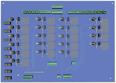
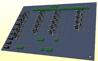
Down the left side are 8 fuse holders, then 6 relays with their driver circuits. These handle the Rad Fan, Coolant Pump, Coolant bypass, Brake vacuum, Power steering, Inverter heat, Motor Heat. Moving to the right is 5 more relays with drivers that handle The vehicles lighting needs if you are using Incandescent bulbs. If you are instead using LEDs (recommended), these relays and their circuits can be left out. Then to the right of that are 5 more relay circuits for towing a trailer. They are also not needed if you don't want trailer towing. The last 4 relay circuits are needed for the headlights, Hi-Beams, Fog lights and leveler jack if a motor home application.
EV PWM Motor Inverter & Motor
The inverter uses the 384v and Ground from the main battery and control from the ADC board. The control is a combination of 2 temperature sensors, a speed (RPM) sensor, a digital speed request, a direction request and 2 enables. The motor enable activates the Inverter placing it in either run or standby. The drive enable turns on the inverter circuit. So with the inverter turned on (drive enable), the inverter goes to standby and presets direction to
either FWD or REV then begins sampling the digital speed and motor enable. Upon seeing motor enable the inverter generates the PWM and or VFD at the 3 phase motor field wires and motion begins at the requested level.
EV Software
As you can appreciate, there was a lot going on in the motor home. We no longer need 2 computers but it still needs the combination drive and accessory one. We will make use of software structure to gain advantage in the control of the EV. But, and there is always a but, there are many sides to the software development. No matter what project, Platform(s), Libraries, Language used, and feature requirements have to be addressed.
Dll hell
In the past programs were written in assembly, pascal, basic, C and used static libraries of functions. Each program was uniquely complete but running multiple programs used a huge amount of memory as many common
functions were not shared between programs. Instead each program had it's own set of functions embedded. Today we have Dynamic Libraries that are loaded into memory as needed and removed when the last program that needed them ended. Sounds great but is a major nightmere. In Microsoft windows circles they call it dll hell. Software company 'A' makes 3 dll's named abc.dll, xyz.dll and atz.dll. Software company 'B' makes a new improved atz.dll that has more features added. Software company 'C' makes a new abc.dll that is totally different than the original, and makes a new atz.dll that only has some of the features. Everything goes fine for the end user until he/she needs software from company 'B'. Programs needing the
original atz.dll start crashing. Putting back the original atz.dll fixes the problem for programs from company 'A' but now company 'B' programs misbehave. In a last ditch effort to fix things software from company 'C' is installed and now almost all software crashes. The end user now needs a major restore.
In the Linux world, they took on versioning as part of the dll name abc-12.4-5.lib and also used different paths so programs had access to the exact version of software it required. In many cases there are two sets of libraries, one set for developing and another for running
applications. Managing the Libraries is a mammoth task.
What Language to use
Our target system is the Arm64 based RPI model 3b+ credit card sized computer. It has all the physical features needed, USB, HDMI, GPIO, I2C, 32GB memory and runs Linux as the OS. Ideally, we could use a PC with Linux to develop the app then cross compile x86 to Arm64 to make the final app for the RPI. The most efficient is assembly language and produces the smallest and fastest code possible. It however, is so low level that every function would take weeks to debug and perfect even if we linked to 'C' libraries. There is very little documentation on using it with GUI's like opengl and qt or gtk. At the other extreme we have xBasic that is powerful and easy to implement and writes the assembly code
for us. We can use 'C' routines for GPIO and I2C operations and it handles Event Driven Programming (EDP) of a GUI with ease.
Unfortunately, xBasic won't run on modern Linux because of Dll hell. It works fine in windows based OS but without GPIO and I2C features.
With Glade we can make a great UI but is very slow as there is no drag and drop widgets. As a
work around I made a program in xBasic called MakXml.exe for windows. It can take our fancy UI designs and coding in xBasic and create the Glade UI file or a qt UI file for the GUI stuff and then build a basic structured python or 'C' binding. Once done, Glade can load the file and fine tune it with much more ease.
With qtdesigner or qtcreator, we also have a great way to make the UI. It is drag and drop like xBasic but has a huge amount of settings to play with for each widget. It is even a slower process to do from scratch. But I have MakXml.exe that greatly simplifies duplicating the xBasic displays as qt-ui files.
The two GUI approaches (glade|qt) handle the interfaces quite differently, glade uses callbacks like xBasic does where event signals are passed to windows then to grids then to children (widgets) on the grid till it is handled. Qt uses Event Sockets and slots where an event is passed to all widgets weather they are windows, grids, or children that are connected to the socket/slot of the event. So for glade/gtk/xBasic, the window has one main process routine that gets all events, another handler (callback) is called if
defined and gets the event(s) which it may or may not handle.
Unhandled events come back to the main window handler for final
handling. For Qt a click() event may have a list of widgets connected to slots. Each widget checks to see if the click was meant for it and handles it if it was.
 For dry test purposes there is a PC work around. It’s a USB GPIO expander that can run under python3 for windows, MacOS, Linux.
CJMCU-FT232H is a single channel USB 2.0 Hi-Speed (480Mb/s) to UART/FIFO IC. It has the capability of being configured in a variety of industry standard serial or parallel interfaces.
Feature:
- Single channel USB to serial / parallel ports with a variety of configurations.
- Entire USB protocol handled on the chip. No USB specific firmware programming required.
- USB 2.0 Hi-Speed (480Mbits/Second) and Full Speed (12Mbits/Second) compatible.
- Multi-Protocol Synchronous Serial Engine (MPSSE) to simplify synchronous serial protocol (USB to JTAG, I2C, SPI (MASTER) or bit-bang) design.
- UART transfer data rate up to 12Mbaud. (RS232 Data Rate limited by external level shifter).
- USB to asynchronous 245 FIFO mode for transfer data rate up to 8 Mbyte/Sec.
- USB to synchronous 245 parallel FIFO mode for transfers upto 40 Mbytes/Sec
- Supports a proprietary half duplex FT1248 interface with a configurable width, bi-directional data bus (1, 2, 4 or 8 bits wide).
- CPU-style FIFO interface mode simplifies CPU interface design.
- Fast serial interface option.
- FTDI's royalty-free Virtual Com Port (VCP) and Direct (D2XX) drivers eliminate the requirement for USB driver development in most cases.
- Adjustable receive buffer timeout.
D0 to D3 are used to configure I2C or SPI in MPSSE mode.
In addition to the serial protocol pins above, the MPSSE mode allows you to control other pins as general purpose digital inputs or outputs. These are great for controlling chip select, reset, or other lines on chips. You can even use the GPIO to read switches, blink LEDs, and
more!
The pins which are controllable as GPIO in MPSSE mode are D4 to D7 and C0 to C7 ,for a total of 12 GPIO pins. These pins can be configured individually as digital inputs or outputs.
- 3,5 = I2C communication
D0+D1,D2
- 13,15 = int4a int4b D4,D5
- 16,18 = int5a int5b D6,D7
- 22 = rpm sense C0
- 29,31 = charge / discharge counting C1,C2,C3,C4
So we have 7 pins needed (9 if using 2 Coulomb counters) to test the software GPIO control and 2 pins for I2C communication.
Adafruit Blinka: a CircuitPython Compatibility Library
Enter Adafruit Blinka. Blinka is
a software library that emulates the parts of CircuitPython that control hardware. Blinka provides non-CircuitPython implementations for board, busio, digitalio, and other native CircuitPython modules. You can then write Python code that looks like CircuitPython and uses CircuitPython libraries, without having CircuitPython underneath.
There are multiple ways to use Blinka:
Desktop Computers
On Windows, macOS, or Linux desktop or laptop ("host") computers, you can use special USB adapter boards that that provide hardware pins you can control. These boards include MCP221A and F232H breakout boards, and Raspberry
Pi Pico boards running the u2if software. These boards connect via regular USB to your host computer, and let you do GPIO, I2C, SPI, and other hardware operations.
The I2C interface connects to the base board and the base board connects to 2 input boards, 3 output boards, 1 ADC board, 1 fm radio, and 1 GPS modules.
To use I2C with the Adafruit Python GPIO library and the FT232H board you'll need to
setup your circuit in a special way. In particular you'll need to tie the D1 and D2 pins
together with a jumper wire. One of the pins will be read by the F232H as an input, and the other pin will be used as an output. When tied together both these pins form the SDA
or data line for I2C. The D0 pin alone will be the SCL clock line for I2C.The second thing you'll need to do with your circuit is add explicit pull-up resistors from SDA &
SCL on the FT232H up to 3.3 or 5 volts. This is necessary because the FT232H does not have pull-up resistors built in to these lines as it is a very general purpose chip. I recommend using 4.7 kilo-ohm resistors as these pull-ups.
To summarize, for using I2C you need to setup your hardware as follows:
- Connect
FT232H D1 and D2 together with a jumper wire. This combined
connection is the I2C SDA data line.
- Add a 4.7 kilo-ohm resistor from the I2C SDA data line (pins D1 and D2 above)up to FT232H 5V.
- Add a 4.7 kilo-ohm resistor from FT232H D0 up to FT232H 5V. This pin D0 is the I2C SCL clock line
Software screens were developed in Xbasic for testing screen
functionality, converted to Python code using xbasic2Python. At this point, the USB GPIO adapter was plugged into to PC and wired to the Dash base board. Adafruit blinka library was added to the PC. Running the python code makes it possible to test all vehicle operations from the PC.
I found this to be the fastest way to do RAD (rapid application development). Once the code works perfectly on a PC, we copy the python code to the RPI computer and change the include library statement from “include blinka” to “include circuitpython” and adjust the GPIO reference pins to match connection of the base PCB to match the RPI pins. Save the new program to the RPI and make a back-up of it so we have it.
The digital dash control center can now be duplicated as many times as we want for as many EV car conversions as we want to do. During tests, a simple PWM inverter to a small AC motor is used but in the actual conversion we connect to the real Inverter and Motor.
Coding dilemma
We are doing a EV motorhome application. The last thing we need to have is the inadvertent hiding or closing of the application while driving! To this end our main windows(s) must not have window frame, control frame, titlebar, or statusbar found in a normal GUI program. Mouse/Trackball/touchpad and keyboard are No-No's while driving so control is by dash switches, steering column controls, Brake pedal, accelerator, and E-Brake. These operator controls use the GPIO/I2C and are also select-able from the touchscreen of the dash display. xBasic, opengl, qt support frame-less/control-less/title-less windows but such might not be
possible with gtk/glade.
Let's start with the basics:
We have physical user controls that are normally used in using a car. We also want to marry these controls to function from software. Then we want to add our own bells and whistles like Radio, GPS, Hands free calling, Self testing and maybe more.
Ignition key Our Ignition key actually turns on the pi-3 computer which runs it's own start-up program to provide display and functionality. Turning off the key will not shut anything down! but when the system is safe to shut down will turn off the system.
Ignition-Start does nothing.
Other changes The following other controls are handled differently than on the regular ICE type vehicle that uses idiot lights, and cables or sensors such
as:
- Left-turn
This line sends a signal to the computer to tell it to show the turn signal as a flashing indicator instead of flashing a bulb on the instrument cluster.
The built in electronic flasher powers the front and
rear lights
- Right-turn
This line sends a signal to the computer to tell it to show the turn signal as a
flashing indicator instead of flashing a bulb on the instrument cluster.
The built in electronic flasher powers the front and rear lights
- Hazard flash
This line sends a signal to the computer to tell it to show both turn signals as a
flashing indicator instead of flashing bulbs on the instrument cluster.
The built in electronic flasher powers the front and rear lights. The flasher circuit gets power all the time even if the computer is off.
- Brake
Here again the computer illuminates brake when the brake is pressed. Normal brake function of the ICE operates the brake.
- E-Brake
Likewise here the ebrake is illuminated when the ebrake is on. It too functions without modification.
- Cruise
When cruise is active the display shows it is on. It shuts off if the brake is applied and normal accelerator action takes over.
- Fwd-Rev-Neutral-Park -- not used FWD / REV switch on dash replaces it
- Wash - Wipe
Is one thing that doesn't get any computer involvement. It passes direct to the wash
wipe control unit unchanged.
- Fan off - low - med - high
Will be handled by the computer. No user control buttons or switches will exist.
- Defrost - Vent
This also gets handled by the computer. No user controls exist.
- Heat level
As dose this
- A/C level
And this
So we now know which things need to be handled directly from our dash display. Everything else needs handling by the support routines and it's GPIO based automotive control circuits.
The EV is marriage between 5 systems that function independently and also must work together. It gets this information from a series of special cards that connected with the automotive systems and the Drive Inverter.
There is one more note to make before we
go into software development. In our final design, when the computer comes on to initialize, it monitors the one User interface we will have. This is a 12 button onscreen keypad or a RFID card reader. To enable driving software you must enter the multi-digit code or use the RFID card. There is one code for programming mode and one for run mode. 3 failed attempts shuts off the system. To turn the system back on you must turn off the key and back on again.
Some structure changes
Having to reach the displays to make changes
using touch screen technology, is fine for testing but in real
driving it is poor design. So we have a marriage between onscreen touch and manual controls (signal lights, direction switch, hazard flash, Headlights, cruise and brakes). The dash display (instrument cluster) has desired cabin temp, Kph/Mph select, Headlights/running lights/hi-beam, Cruise, Back-up display and drive selection to be handled.
How the system does things in software is
covered in a separate document
Tear Down :Out with the Old in with the New
In this chapter we will go over the three areas of concern. The front canopy or engine compartment, the rear fuel tank area, and the interior dash. We will be discussing and showing the removal of things that are no longer required. Then we will discuss and show the implementation of things needed to be added.
The canopy is the containing compartment for the engine, transmission, starter, water
pump, air conditioning pump, steering pump, Air intake, battery, carburetor, exhaust manifold, and alternator that we will be removing. We will be keeping the Radiator, Fans, Windshield washer and reservoir, Radiator overflow, Electrical distribution, Power brake system, Power steering system, and from the front axles to the front drive wheels. We are adding the electric motor, Power Drive inverter, And electric pumps for water, steering, air conditioning, and brake vacuum.
Engine Removal
There are three ways to remove an
engine from a motorhome.
1. Take from the top,
- Pull drivers door
- Pull steering column
- Remove Drivers Seat
- Remove doghouse
- Remove as much as you can from block
- Support Trany and disconnect trany
- Wrestle Engine up and out door.
- Go into cavity and clean up anything left behind
- Make trap door over opening
- restore driver seat, steering wheel and drivers door
2. Take from the bottom
- Jack vehicle up and place on stands
- Pull Front steering
- Remove doghouse
- Disconnect anything holding above
- Support Trany and disconnect trany
- Remove cross support
- Drop Engine out of bottom.
3. Take out the front
- Remove bumper
- Remove front grill work
- Remove doghouse
- Dismantle attachings from above and from the front
- Support Trany
- Disconnect Trany
- Drag engine out the front
4. Drive shaft & Exhaust removal
** It is important to take steps to both measure distances from all sides for drive shaft alignment and / or secure the drive shaft at the correct alignment before removing the transmission.**
This above step will help when the drive shaft is shortened and the motor is aligned for mounting.
Part one: Drive shaft Removal


Locate 4 bolts at the rear differential which may be 8mm Hex head or torx and the remove the retaining brackets that seat the u-joint into the yoke.


Using a crowbar between the coupler and the joint pry the u-Joint out of the coupler.


Replace the brackets for later reassembly once the drive shaft is shortened and mounts are in place for the electric motor.
Step two: E40D Transmission Removal


Being a non-mechanic the steps to remove the transmission are in image form. Essentially, you want drain the transmission of fliud, disconnect the battery, gain access to the the flywheel, Rotate it to access the bolts , remove the bolts holding the flywheel in place, removine linkage and cables, support the transmission, remove the brace below it and drop the transmission.
Step three: Shortened Drive shaft
This can be done either as a temporary shaft replacement or a permanent replacement but for best results you should visit a licensed drive shaft shop and have one made special. You will need in this case to measure the length needed, the yoke diameter and U-joint size.


Mark a centered line length ways down the shaft. This line will be used to realign the shaft ends for re-welding together. It is important that the ends mate in the same balanced linear alignment after the section is removed. Do not cut too close to either end of the shaft.


With the marks in place line the shaft absolutely level with-in the crop saw. Take care not to misshapen the shaft by tightening it too much. The shaft thickness is very thin walled.


Cut, debur and polish the end being kept so a good strong weld can be made to rejoin ends. Repeat for the other end.


Here we realign the ends and tac weld them temporary so we can check trueness. Welding will tend to slightly bend the shaft.

Using a point gauge rotate the shaft looking for as close to zero deviation as possible. only when 100% true can the shaft be welded permanently.
With the drive shaft out of the way and shortened, locate all exhaust components like tailpipe, muffler, Catalytic converter, exhaust ‘Y’ and remove them as they are no longer needed.
5.Transmission removal
Engine must be out to even attempt to remove the trany.
- Disconnect the linkage
- Disconnect from Driveshaft
- Disconnect mounts and either take out through doghouse opening or raise vehicle and drop out the bottom.
6 Gas Tank removal
1. Remove the hose clamps on all lines
2. Siphon out all fuel. 0 to 500 lbs
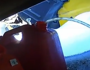


3. Support the tank and undue two straps bolted either end. Bolts have a tendency to rust solid so WD-40 or penetrating oil may be needed. If you get impatient just cut the straps.
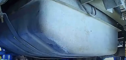
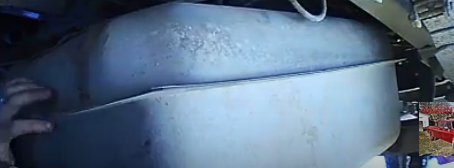
4. Tilt down the tank and remove all electrical and line ends and take out the tank. 50 to 100 lbs
5. Clean up the old tank area and take good exact measurements between the frame rails, and between the bin backs and the rails.
Engine Compartment
Well it's not really the engine compartment anymore...
So what are we doing in here? We are going to remove the radiator, Wiper reservoir, coolant reservoir, Batteries and their shelves, The transmission cooler, Oil filler, transmission filler and the A/C unit.
Once all has been removed, the area will be power cleaned.
We will then locate and place all brackets for our stuff to go
back in then prime and paint blue.

 Hard to see but has battery, oil filler, AC, Radiator, the battery (2 of them for engine and 3 for coach) won’t be needed as the power will come from our battery packs.
The AC unit was removed from the engine and strapped out of the way for remounting with an electric motor.
The Radiator will move to the front just inside the grill and the hydraulic pump remains where it is.

 Cleaned up with opening for new HVAC and shows the engine access where the radiator was. On the other side we have transmission filler, washer reservoir, electrical box, brake booster and steering unit. Cleaned up with steering and brake units not shown. Electrical box will be remade.
An electric water pump will be used from the radiator to the AC unit with a tap for cooling the motor and Inverter.

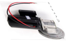
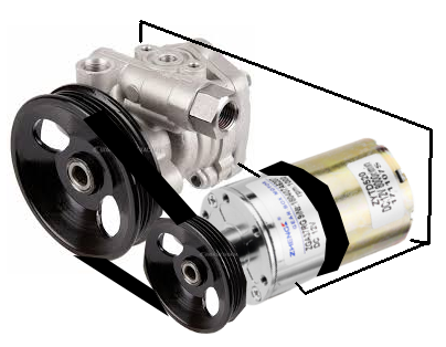
Electric brake booster
vacuum pump is also
added
Electric power steering
pump is added.
Cockpit
changes
Here we are going to remove the doghouse and remodel things so we have a flat floor with access panel. Before
and after views
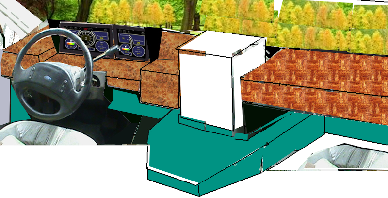

LED custom lights
My first ever custom EV-Motorhome
should be heralded as unique so Lets start with a copy of the
Kitt-car LED EYE that strokes back and forth as the vehicle travels or when Four way flashers are on. In my E-Trike project this was introduced as part of it's front lighting assembly. Now the turn signals will be made separate. The control board will be the same.


11 LEDS will be fit into a clear epoxy frame which is sealed against harms from weather. The frame is made from a clear drop ceiling lens heated and formed into an open front box. Then Led circuit board is placed into the 5" x 0.5" x 0.75" box and filled with epoxy resin. Another clear lens is glued with acetate glue to the top
only after the epoxy has dried hard. Two mount screws holes are then drilled either end. The 12 wires coming out the back then wire to the controller.
Marker lights
 Unlike the E-Trike, the motorhome
has more than just 2 front, 2 back, and 2 side marker lights. It has 4 side marker lights with 2 sets front and rear and 5 at front roof top and 3 at the back roof top. We will have 2 series strings of high luminence LED's with 48 Leds per string. Each LED marker assembly will be 4 Leds along the sides and front and rear with 6 LED's at the roof tops. These Marker lights are made in the same way as the Kitt-car EYE was.
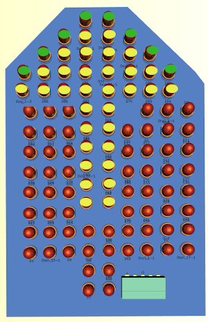 At the back we have these combination lights with turn signals, Marker, and brakes with 40 LEDs for
turn and brakes. The front will not have the brake LEDs. So instead of 6A being used at each marker and signal and brake light we are using 0.02A for markers, 0.02A for signals, and 0.04A for brakes. The license plate light will be white LEDs tied in with the Marker lights. A Sonalert beeper with 2 white LED units are used for back-up.
Coach Control
The coach system has Taken on the duties of Charge control of the batteries, Solar array control for adding solar charging and tilting, Bin heating, Water supply management, Floor lights and Distribution. Originally planned into the dash computer but now to it's own home as a coach control system since the features function when parked and not when driving. There are eight touch buttons to access the different systems.
The breakdown of it features are as follows:
- Battery ... current state of charge of each banks of battery
- Camera ... Record and playback of Dashcam and Rearcam
- Charging ... Select where to charge from and status
- Lights ... turn on/off interior/exterior/floor lights
- 120v AC Power ... Select source of power : Shore/Gen/Battery
- Solar ... Control charge on/off
- Water ... Bin heating, Instant Hot Water, Pump/City
- Shutdown ... turn off the system
Power Center in the coach
In my coach the main power center sits below the fridge. It
consists of a breaker panel, 12v fuse panel and a charger of 3A for the coach batteries. Totally inadequate for the new EV motorhome.
Campground power is usually
15A/120v, 30A/120v, or 50A/240v. The last one is separated in the unit into 2x 120v/25A circuits which split into 4x 12A circuits. The 30A/120v is separated into 2x 15A circuits. To make use of all methods of supply we would need a 230v/50A input added and a new breaker panel.

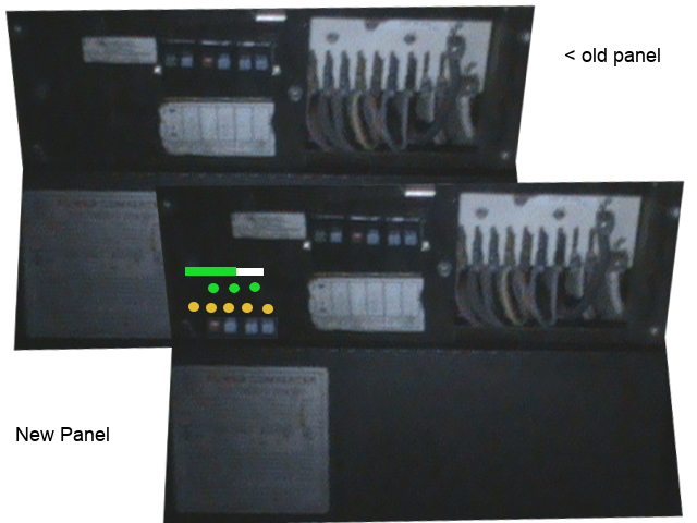 Seen here is the original power and distribution panel that sits below the refridgerator. It housed a trickle charger for the coach batteries, master 30A breaker, 5 services breakers, and 9 x 12v services fuses.
The bottom is the charger and the top has the distribution. It's the bottom part that has to change.
The Inverter/converter will have 120v-15A AC, 120v-30A
AC, 240v-50A AC as input sources. It will have smart charge output 57v DC to charge the battery Packs and the battery packs will have 12v DC for the 12v appliances. It will even have a solar panel input, and it also has 5000watt Genset input
for 43A @120v AC. The 30A Main coach panel will get it's power from the inverter/converter as will the 15A water heat system. As long as we are connected to shore power by one of four inputs (AC) coach operations and batteries are charged till full. If AC fails, the converter immediately switches to the EV batteries to keep things going and if it becomes drained too then it starts the gen set to power things. However, limits are present, The genset can provide only 10 hours under full load, The EV system can provide only 40 hours under full load so we had better hope main power is restored with-in 50 hours or all stops.
 There are 3 more functions to this system. Auto controller signals for connect "Coach to Chassis", "Run Coach from Battery", and 12v DC distribution complete the distribution control board.
The circuit to the left takes 5 different AC charge source systems and feeds them in one pair of SCR's per source. The gates of these SCR's are tied in full duplex mode to trigger signals coming from the GPIO80 & Automotive controller to turn on the selected source. Once on, the source remains active until it gets a charge full reset from the charging circuit. In addition, the 15A, 30A, and 50A systems tie into the coach AC Distribution Panel such that both the 15A and 30A systems
can be active to supply the coach power requirements, or the 50A system can be fed into the system to supply these coach needs. From the 15A/25A feeds, we get an internal switch for selecting bin heat or Instant Hot Water. Actual control is likewise controlled by 3 enable triggers that are also reset by the full charge reset. The water pump is controlled by a final GPIO80 trigger.
And this will run from our new Coach Computer with touch display. The 120v system will still use the Breakers and 12v fuses to their respective systems but, two new breakers are added for the bin heat and solar array systems.
The coach display unit
To keep wiring needs to a minimum, the display will be fit into the wall at the Fridge since the space under the fridge has the current breaker panel which will be replaced to house all the system electronics. If I did this, all the coach systems would be almost localized. Two systems for the coach are still not planned in. The Entry step control, and the floor lights are currently in the dash system.
I am abandoning the multi shore charge sources as overkill. Not all RV parks have 50A service, and no parks have 300A service to date. 120v AC @ 15A and 120v AC @ 30A are standard. The 3000 watt to 5000 watt GenSet will be propane supplied instead of using gasoline and will tie in as a third power source for the 120v AC. The fourth source of
AC is pure sine inverted from the battery bank(s). So we have 4
sources of AC feeding our 120v distribution to the coach.
Looking at the charge side of things, the 3 AC coming from the shore power and GenSet feed a 120v to 60v transformer which after rectification is 57.5v DC. The Solar array of 19 x 1A panels provides 57v DC @ 19A charge. Both charge sources can be fed to either or both battery
banks. In charge mode a bank is switched from 8x 48v series blocks to 8x 48v parallel blocks. There are 2 banks. A bank not being charged can be used to run from. When running from battery, the series blocks make up 384v which feed a pure sine inverter to supply 120v AC @ 30A. Each bank has 2 coulomb counters. One in each bank counts discharge from the 384v run mode. The other one in each bank counts charging.
The coach computer therefore can check when batteries are fully
charged or discharged and take action.
This alleviates running several banks of batteries of different voltages or doing any dc to dc conversion.
Like the Auto Controller of the dash computer, we will be using a distribution board with daugther boards. GPIO-1a, GPIO-1b for Enables, GPIO-2a,
GPIO-2b for lights. GPIO-3b is input digital sense and ADC-1 is
analog temperature. Solar tilt is no longer included.
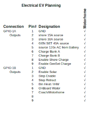
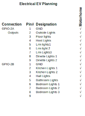

Looking at the left chart, 15A service supplies the bin heaters and IHW. If no 30A is available it also tries to supply the 30A side. The 30A service supplies the whole coach except for bin heat and IHW unless no 15A is
available. If neither is available or they have been shut off, the GenSet connects to both systems. Selecting run from Battery disables all other sources. When charge Bank A is on Bank A switches from Run to charge mode. When charge Bank B is on Bank B switches to charge mode. If both banks are in charge mode you can't Run from Battery. Enable shore charge turns on the charger until either manually shut off or the batteries are full. Enable GenSet charge turns off shore charge and attaches the GenSet as the mains.
** The solar tilt and cover feature was abandoned due to complexity and weight so the GPIO32 functions are moved to the RPI 3 module and solar motor control removed.**
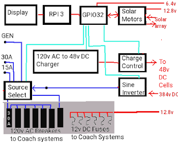 The GPIO-3A/B group of outputs control the solar array. When open solar is selected solar panels are uncovered and recovered when open is off. Enable solar connects the solar panels to the charger. If the batteries are charged Enable solar is turned off. The next 6 items control the solar tilting
The second chart has provision for lighting control.
Next
we have the input items these inputs read hall-effect sensors on the panels to signal when panels are at a specific location. Lastly we have two temperature sensors that provide for cabin heat and Battery heat values.
As you can see the coach system layout is quite different now. In Grey we have the original with two sources GEN & 30A. It had a 120v AC to 12v DC charger @3A. Now we have Selectible Source for AC, a considerably more powerful DC charger @60v, can run from battery if necessary, full charge monitoring, and solar charge
all under computer control with touch display.

The wall at the fridge has 9" of space for mounting the width of the display and we must stay below 4" of depth.
The RPI has many 7" Touch screens available for it so we can meet the width requirement. A 7" Display is roughly 6" wide by 4.5" tall and 1" Thick. The raspberry mounted to the back is another 1" thick so we are under the 4" limit. The
enclosure will have to be determined based upon system space
requirements. Instead of adding a 5v 3A power supply we will use the 9.6v tap and regulate to 5v.
Power for our bin heat and instant hot water was ran from a separate 15A 120v feed which could be plugged into the exterior passenger side connection if the campsite didn't have both 15A and 30A power available. In the
above depiction, we have almost got the system planned the way we want it but, and there is always a but, there needs to be a means of connecting the 15A to the 30A when either the 15A or 30A is not connected. Without such a bypass, you would need to go outside and plug the 15A line into the external socket of the 30A system. Not ideal, as it only solves for missing 15A service.
Charger module When commanded by the computer, enables Battery bank 1 and or 2 for charging. Whatever bank, if any, that isn't selected becomes available for the coach. Charge can be directed from AC or the Solar array.
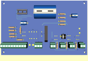
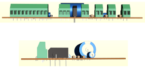
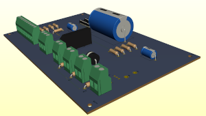
This was our original charge module for the EV Motorhome. It had a single coulomb counter for charging/discharging one or two banks. Because we are having the charging system handled by the coach system when
parked and by the dash computer when driving, we need to modify this system to have two coulomb counters (one for driving/regen and one for charging one or both banks. The coach 30A connection needs to be tied to the 30A breaker panel rather than have it's own separate plug-in. Lastly, it won't do to connect both drive system and the coach system in parallel without some intervention.

Of the pins, pin 8 (AC En) is exclusive to the coach system. Pin 13 goes to a latching relay powered by the coach system that must connect the other pins to one of the control systems. Pins 1 and 14 are powered by the Battery pack at .001mA when neither system is engaged and up
to 20mA when either system is charging or running. Being that we can hard wire the board for interrupt design, pins 2 and 3 aren’t needed. This leaves us with 4 Enables from the selected computer control, 3 interupts to either computer and a directional POL signal to either computer. They are all logic
level signals so we could use 74LS244 bus transciever chips to
separate one PC from the other.
When I designed the Dash system which originally was to control the coach systems, I had the dash send signals to the Source system to select which source to use for powering the coach and which to use for charging. These went to latching relays so that when the drive computers were off the latch relays maintained settings. But, and there is always a but, to make a change one would have to start the
vehicle and since only 1 or two connections would be active at any time, it doesn't make sense to use IGBT's (28 of them) for switching sources.
28 SCRS were used to create 14 AC pathways that can be
individually controlled. 5 paths provide choice of AC run source, 3 provide IHW and bin heat control, and 6 others handle charging distribution. Note that because of high currents possible during charge cycles, 4 SCR's are used for each Pack. The main charging Inverter/converter has 3 Battery state of charge sensors, 190A @384V charge and a 95A 12v charge. The converter has 384v DC to 120v AC pure sine wave inverter.
WOW! what was I thinking. 95A is enormously dangerous at 12v DC but almost 200A at 384v DC is criminal and extremely expensive wiring. The cables alone would cost over $2500 and the protective circuits would need to be custom and could run $10,000. Converting to a 48v system
throughout with up to 60A charge is so much better. True I don't get 1.5 hour charge time but I gain safety, available parts, and almost nothing in costs.
So our new charger control needs to have some additions but is functional in concept.
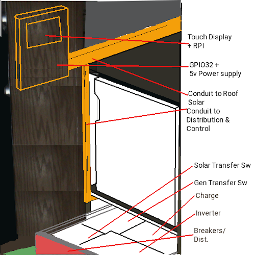
Our new distribution system has 2
shoreline sources, the Gen Set and Pure sine wave conversion of the 240A 384v Battery. A 10 Breaker panel is needed for the system. The Gen Set contactor and 120v AC sockets are the only components of distribution not to reside with the breakers. Behind the breaker panel is the charge and inversion systems. Rather than make a converter from 48v to 12v I simply tap 12v off the lower 4 Gcells of Bank 1. This gives me 12v DC and cell balancing should have no problem topping up string 1. The Sine inverter, DC charger and Coulomb counter will reside under the Fridge in a drawer with the breakers at the front. Two High voltage high current line come into the drawer (144A 384v, & Traction Supply). The 120v AC line from the Gen Set will feed into the drawer to a contactor and then pass on to the distribution panel.
EV / MH power center
The power center is now radically different from the original design which tied charging, coach operation and vehicle drive into one massive inverter
converter. It is a far better plan we have now. Keep the Driveline separate from coach and keep high voltage and currents out of the living area.
Five systems that work independently and together. The main Battery banks have
independent shutoffs, with 3 Master shutoffs. Master shutoff 1 works in conjunction with the Inertia Switch and either can cut out the 384v 144A Battery system. Master shutoff 2 kills 12v power @ 120A from the Coach system. Master shutoff 3 kills 12v @ 120A power to the Dash and automotive systems. The Propane has a Shutoff at the tank to stop both the gen set and Coach appliances from operating. The coach system has a maximum run time of 24 hours during a power failure. This is paralleled by the Dash and automotive system with a 300 hour run time if not moving and of course shorter run time if driving. The
traction system has the highest demand with a travel range of about 65 miles.
Ideally, the solar array and Batteries are not considered systems as they are dependent on
other systems to function.
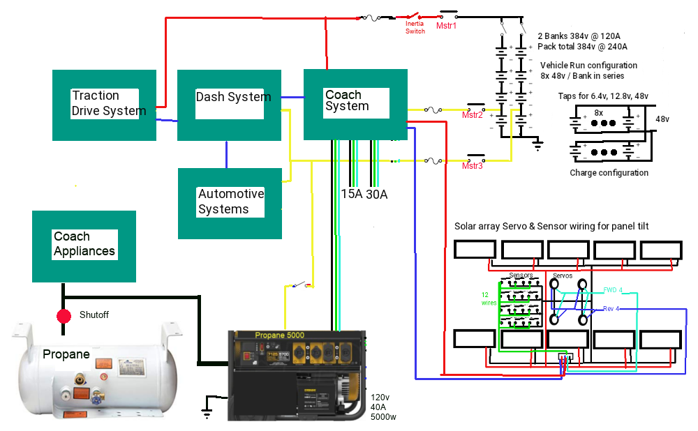
Coach Software
When we get to the screens again we will show the look rather than a huge amount of code used to define them.
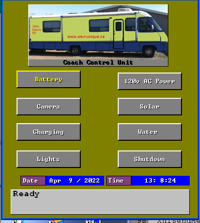 The main screen is a simple 8 button menu
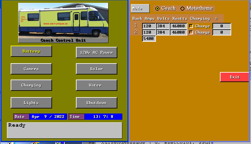 The coach system is powered by a simple On/Off located at the base of the panel. When turned on, The raspberry PI does it's start-up and presents the above screen view. There are 7 displays selectable by the screen and a shutdown button. Current date and time display along with system messages.
This routine has the timeout code added to it to both initiate date and time function and also to allow interrupt processing to be done. Where the Interrupts functions with-in micro-seconds of an event to capture and set values, the handlers are called every 10 mili-seconds to take care of anything that has happened.
In coach mode the coach has control, in motorhome mode the drive system gets control. As can be seen either or both battery banks can be selected for charging.
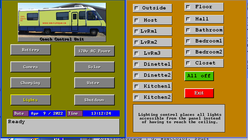 There is provision to control all lighting from this panel display. Many motorhomes have the light switches at the ceiling. Short people and children can not reach them there. This panel allows more comfortable light control.
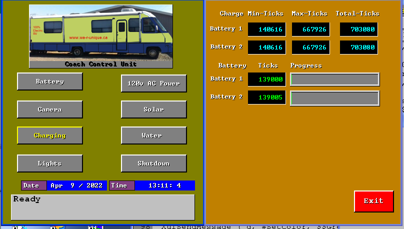
The charge Display shows the number of ticks for the selected Battery Packs defined. The minimum ticks is the recommended minimum that leaves 20% charge in the Battery Pack. The Max Ticks is the top charge of 95%. Battery use between these limits is acceptable for long battery life.
Current battery charge in ticks display while charging or discharging by way of running from battery.
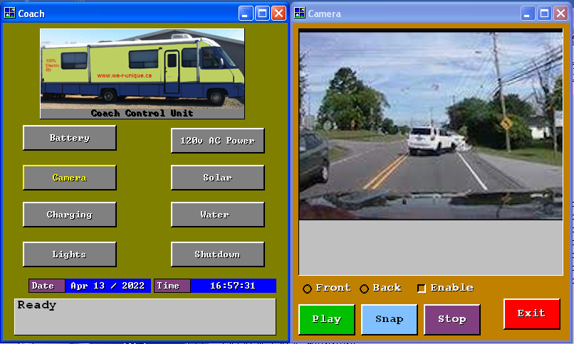
The video record and playback screen
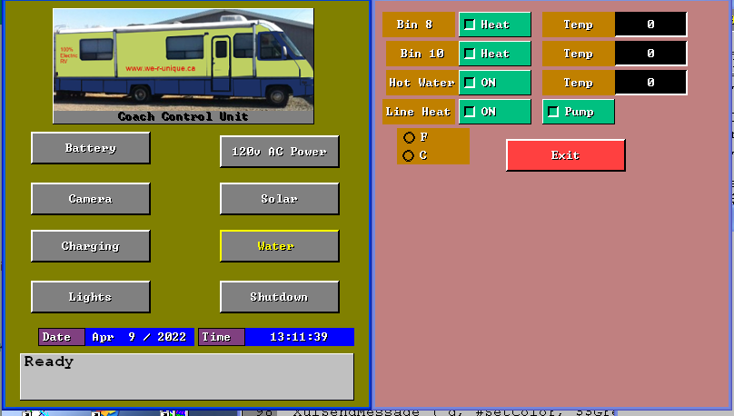 Selection of the Water option provides control over bin heat, (so water doesn't freeze), Instant hot Water, ( on in summer, on when used in winter),Line heat ( in winter so water supply does not freeze), and Pump (on for internal water off for city water.)
Two ZC Triacs control 15A AC supply to each of Bin 8 bin 10 IHW and Line heat. A 12vDC SCR Turns the pump On/Off and the City valve Off/On. Three Temperature sensors read temps at the locations.

And finally, you can change between F or C for temp readouts.
The solar array tilt has been eliminated.
 Choose AC Pwr to direct the source of AC power. You can source AC 15A and AC30A at the same time, Source AC 15A and Genset at the Same time. Source AC 15A and Run From Battery at the same time. No other combinations are valid. As you change the AC source the image changes to reflect what you have done.
Battery space planning
Here I am trying to demonstrate that there are options to how you organize the batteries into packs depending on your particular set-up. For me I am still trying to find a motor / inverter powerful enough to handle the load
of the motorhome. I don't have definitive answers at this point from any sources so I have to keep my options open.
 For each vehicle there will be differing dimensions these are for my unit. Between the frame rails and the bins there is 8" , the rails are 5" wide and 9" high spaced 34" apart
Working right to left (back to front) there is 121” of space between the bins and the frame on both sides. Between the frames is 34” with a tire cavity of 41” at the back. Then there is an 80” x 34” cavity for the fuel tank. Next are the rear axles followed by 86” of space between the bin and frame on both sides. Between the rails is 34” x 234” of space from the rear axles all the way up to the front.
The bins themselves are 23” high x ~41” wide x 18” deep. The top 10” pass through to the bin on the other side. With 8” between the bin and rails. Battery space is therefore 207” L x 8” W x 13” H on each side. Accommodating 10”x10”x6” Gcells @ 42A ea. We have room for 20 per side. 8 Gcells per Bank = 1.5 banks per side. The 80” x 34” fuel cavity has potential to hold 8 rows of 3 Gcells 10” x 10” x 12” = 3 banks of Gcells @ 84A or 12 rows of 10” x 30” x 6” Gcells @ 144A = 1.5 banks.
So we can have 2 banks of 42A Gcells between the bins and rails either side and 2 banks of 84A Gcells in the gas tank area. Driver side rail Gcells wire in parallel with Gcells on driver side of fuel tank area for total capacity of 126A per bank (252A Pack). We could also do 1 bank of 144A Gcells in fuel tank area and do 4 x 144A Gcells on each rail space as the second bank for a 288A Pack system.

2 banks 42A = 84A Pack 544lbs 13 miles/charge
2 banks 84A = 168A Pack 1088lbs 26 miles/charge
2 banks 126A = 252A Pack 1632lbs 39,5 miles/charge
2 banks 144A = 288A Pack 1843lbs 45.13 miles/charge
These figures are based upon a fully loaded trailer with car at full weight capacity of trailer. On a 144A per bank system there is a potential to 8 of 10” x 10” x 6” 42A Gcells in the fuel tank area which would increase 1 bank to 186A while the other is 144A. The weight becomes 2112lbs. 51.72 miles/charge. (102km). Without solar charge we have 2395lbs available for batteries. With 22A Solar we have 1757lbs available. With 19A solar we have 1844 avabeilable. With 2112lbs of battery we can have 10A of solar charging.

We are not using any space between the front canopy and the rear differential between the frame rails for batteries.
The last 330A system does put 1620lbs behind the rear tires and 500lbs between the front and back tires. If we move the rear 4 144A Gcells up with the front 4 Gcells weight is more even but we are using 12” of our 34” width between the frame rails for battery placement.
Generator System
This will be replaced with a propane 5000 watt model and tied to the custom inverter / converter. The gen set can be started manually, by the auto-start/stop at the Coach control center, or automatically by the EV power converter. Under full load it can run for 10 hours. It can provide 74A @ 48v recharge = 1 bank 144A Gcells 50% in 10 hours.
Coach house Inverter
The inverter bay was formerly where the propane hot water tank was. It will now have the Genset transfer switch, Cutoffs for Banks 1 and 2, and a pure sine wave 60 Hz Coach inverter that will upon command convert 48v
DC to 120v AC @ 30A 7000w. 29Hours run time per bank if
using 144A Gcells. Figures assume using full load @ 30A.
Install &wire the Inverter transfer switch and cutoffs
The 7000w Inverter has a remote enable from the coach computer. When run from battery is selected, you have a choice of Bank 1, Bank 2, or both. The computer then configures the 8 Gcells of each selected Bank into
parallel. The 48v charger line becomes the 48v Inverter line and is passed to the pure sine wave Inverter which gets an inverter enable signal and 120v Inerter output goes to the coach system controller.
The Genset has a remote start/stop Relay run from the output from coach computer, and a high power solenoid also run from the coach computer. The solenoid when activated transfers the 120v AC from the Genset to the coach system controller.
The Inertia Switch connects between the two 384v bank cuttoff switches. It feeds up to a master cutoff switch under the drivers seat and from there to the Traction Inverter. If the Inertia switch trips all power from the batteries is cut off until reset. If the Master shutoff under the drivers seat is off, again all power is cut off. If either Bank shutoff isn’t in the run position that bank can’t be used for traction drive. Down at Each bank of batteries is a crossover board. It has a series of high power Mosfets that pass 384v to the appropriate Bank Cutoff Switch. The Mosfets get a computer signal to enable 384v drive for bank 1 or bank 2 or both. The crossover board also has Mosfets controlled by the computer to configure the 8 Gcells from series to parallel for charging or run AC from battery modes. In this case the 57v charge line either feeds 48v to the Coach inverter or gets fed 57v from either the 120v to 57v charger or the 57v Solar array.
Install &wire
the Motor
The Motor and traction inverter get mounted at the back closer to the differential. A shortened drive shaft connects the differential to the motor shaft. The motor secures to the frame rails as does the Traction Inverter. There will be 3 heavy phase wires from the Inverter to the Motor and 3 to 5 light sense wires as well. Two low power enable wires, 3 low
power accelerator wires, 3 wires for FWD / REV Selection and two wires for 384v supply go forward to the Master shutoff and canopy controller. In this manor all high voltage and high currents remain away from all human occupants.
EV Vehicle< Solar Charger system
Adding solar charging to any EV vehicle could be a great feature for us to have. Ideally, you want to have 57v to charge a 48v Gcell. In run mode the Gcells are organized Pack voltage/3.2v to make the voltage in series by Pack Amps/cell Amps in parallel. This is how auto-makers make EV. Pack voltages range from 312v to 460v in Auto-maker EV. Pack amps range from 300 to 600 Amps. There is no hope of adequately charging such high100.00% voltage from Solar on a vehicle.
We want the most affordable way for people to get an EV so we go with 48v Gcells that are comparable in size to a standard lead acid battery, less than half the weight, are owner replaceable, and come in sizes 42A, 84A and 144A. Wire 8 Gcells in series and you get 384v @ 42 or 84 Amps, 144Amps. Call that a bank. Make an identical second bank. The banks now wire in Parallel and you have 384v @ 84A or 168A, or 288A. Add an electronic switcher and we can now run from one bank until it is depleted, switch to the second bank and continue to run from bank 2 but the depleted bank can be solar charged. When a bank is switched to charge mode the Gcells reconfigure into Parallel. As a Parallel set of Gcells the Amps add together so a 42A Gcell becomes 336A for charging, 84A Gcells become 682A and 144A become 1152A. From
15A shore power, charging is 57v @ 37A per bank (9, 18, or 31
hours). If we can get Solar to charge at 40A, you could drive to work park and work your 8 hour shift and drive home on bank 2 because bank 1 still has 12minutes left on it’s charge cycle. Once home you plug in to charge bank 2 or you can go back to work the next day charging bank 2 then switch to bank 1 for charging it while you work. This works if there is nice sunny days to never have to charge if your travel less than 32 miles to work.
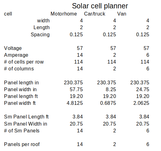 When there is insufficient sunlight the solar panels need a blocking diode to prevent battery pack discharge. A Coulomb counter at the switcher keeps the computer informed of the battery state of charge. We now know the ideal situation but life is not ideal. Vehicles have different roof sizes with differing obstacles. A sunroof or roof rack or rooftop carrier can spoil things quickly.
- Small car 1728sq in. (4ft x 3 ft) [1panel]
- Regular Truck no canopy 1152sq in (4ft x 2 ft) [2 panel]
- Regular Truck w canopy 5750sq in (10ft x 4 ft) [5 panel]
- Mid size car 2880sq in (5ft x 4 ft) [2 panel]
- Large car 4320sq in (6ft x 5ft) [3 panel]
- Crew cab 2880sq in (4ft x 5ft) [2 panel]
- Class A Motorhome 22,464sq in (2 x (3ft x 26 ft)) [19 panel]
Using the chart at the left we see that for the desired voltage a 1A panel 4ft x 2ft gives us 57v so a small car or regular truck can only have 1A charge so we could get 8A during a day while at work. 2% of what we used if we used 42A going to work. The 1A panel actually can provide 2A if bright sunlight. A truck with canopy could have 5 panels or 5A for 40A recovery 12%. A mid size car or crew cab could have 2 panels or 2A for 16A daily recovery. A Large car 3 panels or 3A for 24A daily recovery. And a class A could with a little tweeking have 3 panels across roof x 6 rows down the roof or 18 x 1A panels. We might even be able to squeeze a 19th panel.
Panel weight is roughly 29 lbs taking into account plywood backing, u-channel, Lens and polychrystaline cells. These weights need to be included in the conversion calculations.
If we presume a small car 4000 lbs including 384v @ 42A battery banks. We get a 32Kw Pack so our total range is 32/0.4 = 806 miles. Average person drives 32 miles per day according to insurance bureau of Canada. Technically, we used 3.33A a day for two way travel. So from bank 1 we used 1.66A getting to work and Solar recharged 1A over the day. By the time we get home we will have only used 2.32A so shore charge becomes 1.01A x8 = 8.08A/37A = 13 minutes or $0.08 from the power grid @ $0.17/kwh.
At the other extreme we have a 17000 lb class A motorhome pulling a trailor 24000 lbs with 384v @ 336A Pack. We get 129Kw Pack with total range of 129/2.4 = 53.75 miles (89.5km) to jump between campgrounds 70km apart. With average travel time being 1.5 hours or less we get about .75 hours recharge of bank A or 1.78A of the ~300A used. While camping we can recover 17A during the day and switch to shore power to recharge at 37A over the next 7.6 hours for about $6.12 if they charge extra for power. That’s it cells are charged
ready for next move. If we loose shore power our rig can run from battery for 8.4 hours on inverter assuming we are drawing 30Ah or longer if draw is less. And we can solar recharge or Genset recharge.
Our coach monitoring system in a motorhome application will handle the charging to make sure an over charge does not occur. Essentially, once charged only driving the motorhome or handling a shore power failure will deplete the battery banks.
Panel Planning
Our roof space is a total of 30 feet by 8 feet. This space is occupied by 2 skylights 2.5 ft by 1.5 feet, two Ceiling vents 14 inch square, 2 airconditioners 16 inch square and 2 exhaust vents. So 240 sq ft reduced by 20.5 sq feet. So maximum space for the solar array is 220 sq ft. This can accomodate 3402 4 inch by 2 inch polycrystaline solar cells. We need to obtain 57v per panel which at .5v per cell means we need each bank to be 114 series cells. A 4 ft x
20” is needed to accommodate 5 strings wired in series for 1A. All Panels wire in Parallel to give our working Amps. Across the front we get to have 4 panels then down the outside edges we get 6 each side with 6 split panels (3 rows in one and 2 rows in the other) to give us a total coverage of 22 panels or 22A total.
Acquiring 2508 cells + 5 sheets of ½”
plywood will cost about $1005 plus the lens and trim $88 and $396 respectively. Total cost $1489. The solar array wattage is 1254w. Panel weight is about 29 lbs each. 638 lbs for 22.
The panels being on the roof and in the open means they can suffer damage from snow, hail and tree branches or other debris. Coming inside the coach we need a control center for the charge system that must handle 120v AC
@ 30A & Solar charge, and Genset charge. The Charge control system also handles the distribution system. So ideally, it needs to convert 48v DC to 12v DC for the furnace, c.o. detector, fridge, 12v lighting, water heater, & water Pump. (note: on my rig the fridge and water heater don't use 12v). It also must handle 120v distribution to the 5 systems connected to the breakers. Our system therefore will need a Raspberry Pi and a monitor with touchscreen, a controller, and an inverter/converter/charger unit, and the distribution panel. In this way we can handle shore charging, solar charging, handle 12v - 48v - 120v systems for a true off the grid experience.
This brings us to the last part of the plan. We must collect all the energy from the panels and get it down to the controller and subsequent battery banks. We know from the above details that we could have as many as 22
panels of 114 cells. Each panel producing 57v @ 1A. There is nothing that says we have to arrange things this way. We
could just as easily organize them into 4A or 6A or 8A panels. The difference would be just the number of cells per panel and how they are wired. For each 4 inch by 4 inch square we are producing 1v @ 1A. Panels wire in parallel resulting in just
2 wires making the journey to the charger.
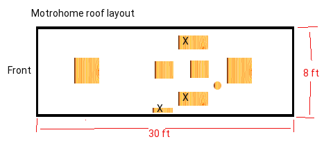
The roof has 3 area's marked with an
'X' these are to be eliminated and returned to normal roof space. The smallest one was for venting the old propane fridge which is now electric. The two skylights have never been useful they only serve the purpose of letting water leak into the coach, and making the coach hotter in summer and colder in winter. Before I blocked them off from the inside, we had temps 10 degress higher in the summer and temps averaged 15 to 20 degrees colder in the winter. In one case we had to run the AC more and in the winter had to run the furnace more. Both situations can be expensive.
I had made elaborate
plans for an auto tilt servo system but have decided against it due to complicated construction and control and huge added weight.
Looking back at the roof, if I do get rid of the skylights, I can have two unobstructed spaces 3 feet by 28 to 30 feet. With 8ft x 28” Panels we can house the equivalent of 2 full panels with 2x 2/5ths panels x 3 on one side and do 3 x 8ft x 20” down the other side only using 3 sheets. A fourth sheet will do us 8ft x 20” across the front and do 2x 8ft x 1ft panels leaving us short by 1 x 8ft x 1 ft to complete our array.
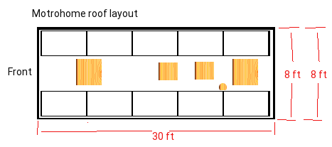
Here we organize the panels 5 per side 6ft x 3 ft each. But
have chosen the configuration just discussed.
Wiring the array
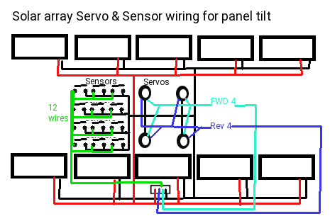
We
are not doing auto tilt so panel wiring becomes just 2 wires red and black going in parallel and passing to the controller.
Shown at the left is the wiring of the panels. The old fridge vent serves to pass the wiring into the coach and down into the main control center.
EV Motorhome Solar Charger system
By eliminating the tilt operation we eliminate 4 GPIO expanders and the associated board and can handle everything from a simple board controlling all
functions right from the RPI computer on the wall.
The 57v Solar array is isolated from the 57v supply by a blocking diode so when the sun is not hitting the panels the panels can't draw from the Batteries. A contactor is enabled by the computer to control charging the batteries from solar so when the Batteries are fully charged the solar can't over charge them.
This is the second solar system I am doing. The first was a 2 panel E-trike system for 24v. For the Motorhome the coach system handles shore charging and solar charging. References to a Mini-Van system was for a Mini-Van conversion which is basically the same for an EV Motorhome on a smaller scale.
In all 3 renditions, the solar charge is a supplement to shore power charging. In the case of no shore power the solar system could be used. For those tied to Gas hogs or hybrid vehicles and even current fully electric vehicles, they don't have options if there is no charge station before their batteries die or fuel runs out.
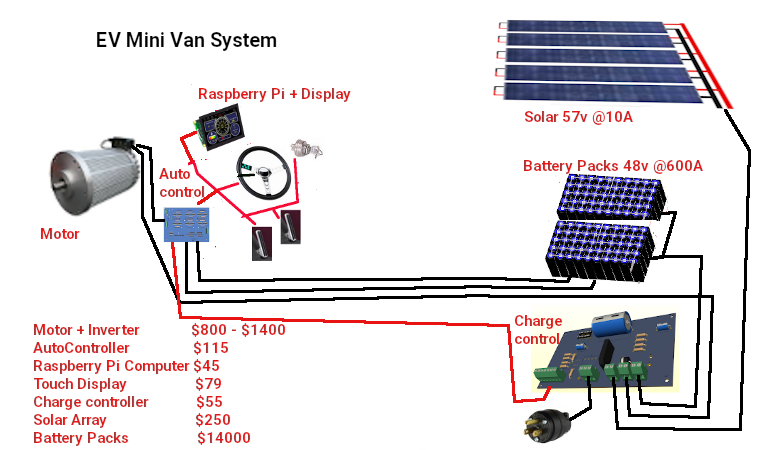
In a vehicle conversion scenario, the vehicle drive computer handles the charging rather than using two systems. Coming inside the Van we need a control center for the charge system that must handle 120v AC, @ 15A, and Solar charge. The Battery banks provide 384v with taps
for 48v, and 12.6v. Our system therefore will need a Raspberry Pi and a monitor with touchscreen, an Automotive controller, and an inverter/converter/charger unit.
This brings us to the last part of the plan. We must collect all the energy from the panels and get it down to the controller and subsequent battery banks. Point is that to minimize the wiring you want to have as few wires making a journey as possible. Because we are making the panels 57v we have already cut the wiring down to 2 wires. When the sun is poor or non-existent, a blocking diode in the controller prevents the battery from discharging through the panels which would destroy them.
As seen the 14:2 cable comes from the solar array down to the coach system controller. The battery banks also feeds into the distribution panel near the controller. Our electronic processes use 3.3v, 5v, and our automotive systems for lights and fans and heaters
need 12v and finally the Motor uses 384v. Typically speaking we need 3A for the 3.3v and 5v lines, and 10A for the 12v line. In the old 'ICE' design it used 12v @ 60A for the systems and 12v @ 600A to 800A for starting. The 384v line from the Battery goes to an inertia switch mounted to the frame then passes the 384v line to a Shunt resistor before traveling up to the engine compartment.
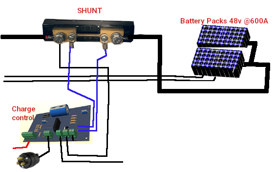 Three wires also come from the shunt resister to the controller at the charge port. You can note that the heavier black wires are high current lines that pass outside the interior along the frame and the lighter / smaller black wires are low current that pass into the charge port controller.
Charge Port at old fuel door.
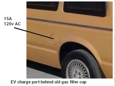 Ideally, you want to minimize changes made or at least hide them. So in this case I will remove the gas filler along with the tank and put an interrupt switch with plug socket at the filler hole. The interrupter switch prevents drive away if the cable is still attached. It also
enables the charge inverter to convert 120v AC @ 15A to 57v DC at 37A. The solar charge system provides 19A to 38A. Alone, it can charge the 288A battery in just shy of 62.25 hours. With solar charging it can replenish in 30.72 hours.
missing image of motorhome charge port
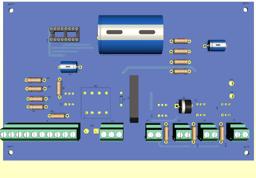
Starting at the left, we have a 10 pin connector that feeds to the console computer. It provides Pol and interrupt signals and shutdwn and clr commands to a charge counter that is coulomb based. It also has +5v, GND, and charge enable lines. Below that is the 120v AC charge line that uses a microswitch at the charge port to indicate when the charge line is pluged in. The AC feeds a transformer and full bridge circuit to supply the charge. U2
is a 15A Triac controlled by the computer to enable charging. U1 is a coulomb counter chip that samples the voltage drop across a shunt resistor connected across two pads at the top. On the right are connectors for the Battery Packs, Main system line, and the solar charge panels. The Inertia switch (not shown) connects between the main line and the Motor Inverter circuit.
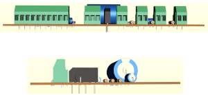
Dash computer - Charge control
The coulomb counter sends one pulse each time .00017A pass across the shunt. It also gives a POL signal 0=Drain 1=charge so the computer can see how much battery use has been used or replenished. So as you drive, the computer starts with a full battery 703,080 ticks = 120A. Each time the coulomb counter gives a tick the full charge comes down by one. So if ticks left has reached 140,616 you have 20% charge remaining. You stop and connect to 120v AC and the computer sees the charging ticks and over a period of time sees it has now 140,616 ticks, it knows it has 20% and needs
to continue changing. When it again reaches 703,080 it knows it is full and can stop charging. Because it can read charge from both solar and 120v AC it can see charging action from solar even when stopped during travel. The motor draws nothing unless moving.
Solar charging is a method of charging Batteries using the power of the sun. While It can be designed to charge at any voltage, typically they are made for 48v systems and use a charge controller and can handle up to 4000 Ah given the right equipment. How effectively it charges is dependent on size of panels, number of panels, available
sunlight and hours of sun exposure.
Applications are also wide ranging. There are small panels ideal for portable use
to charge small electronics like cell phones, PDA's, iPads, and Laptops. Larger panels can be used on vehicles to either keep a full charge on a battery such as Lead-acid, Ni-Cad, or Lithium ion Phosphate. Going with even larger arrays of cells you can do more than just charge maintenance. The Larger arrays may even replace the need for shore power on RV's, or work as a back-up system on brick and morter buildings.
Each basic solar cell has a nominal voltage of 0.48v and depending on size of cell can deliver 0.5A to 1.96A, in the right conditions of sunlight. To charge batteries that are at a higher voltage, you would
place several panels in series to achieve the desired voltage. To increase the charge current, for faster charging, you would connect them in parallel. In this manner, making an array of 5 panels in series by 5 panels in parallel you would get 2.5v at 10A (using the larger 52mm x 104mm cells). This would not be enough for a trickle charge of a lead acid 12v battery. 28 cells in series would be required to provide ~14v but in trueth 36 cells would give best results. Thats 180 cells to make a 10A 12v charger.
The standard Photovoltiac cell is 156mm x 156mm (6" x 6"). The available cell sizes
- 39x26mm 0.5v .36A
- 52x52mm (2"x2") 0.5v .98A
- 52x104mm (2"x4") 0.5v 1.96A
- 52x156 (2"x6") 0.5v 3A
- 156x156mm (6"x6") 1v 3A
An array to charge the 12v Battery with 36 cells would be 2016mm (80") long including the cell spacing and 4" wide. It could be configured as 2 rows of 40" or 4 rows of 20". At 2A it would take 30 hours to fully charge a dead 12v 60Ah lead acid battery. Given that the sun is up only 3 to 9 hours a day, it might take the array 3 to 10 days to fully charge the battery. This brings us to the next hurdle. What happens when the sun goes down? If you connected the battery directly to the solar cell for charging, the battery would discharge through the cell when there isn't enough light. This is bad for the cell and for the goal of having a charged battery. Using a diode, which conducts power in one direction only, we can prevent this discharge when the sun goes down.
The charge controller is a device that is used to match the panels to the battery system and handle the charging operations. They are normally listed by wattage rather then by voltage and current. So for our 12v
60 Ah battery, we have 720w (12 x 60). The controller may do more than just prevent discharge when the sun goes down by configuring the panels (in watts) into a specific output voltage for charging and regulate the current coming from the battery or going into the battery. Often this includes overcharge and overdrain technologies. You don't want to keep charging once the battery is full or to continue draining from the battery once it is too low to supply power.
Panels themselves, are premade of either monocrystaline or polycrystaline cells. monocrystaline do so in a much smaller panel than the polycrystaline ones and are more expensive. The Panels themselves are fairly thin but mounted to a heavier structure or frame to give it strength in adverse weather. For optimum efficiency you need to keep the panels clean from dirt and debris. Often you may find various adjustable mounts for aligning the panels to the best sun quality. Some controllers have the ability to change the angle and direction of the
panels for highest sunlight transfer. Before moving on lets talk a bit about cost comparison. A monocrystaline cell can typically cost about $3.60ea. Comparing to polycrystaline the cost per cell is $0.13ea.
Now lets make it happen
Let us look at our motorhome. It has a 384v 288Ah battery system that we want to charge from a 48v solar. To do this we need to either multiply 48v by 8 to get to 384v which involves a transformer and considerable power losses or we can convert the 8 series 48v blocks into 8 parallel blocks for charging and switch them back to series for running. Method one (transformer) is huge at 10" x 6" x 8" and due to losses is less than 65% efficient. The unit will typically cost over $150. Going
with a switching method, we can use 6 Mosfets at each of 8 x 48v Gcells. Costs come down to $64 or less, weight comes down from 10 lbs to 2.4 lbs, and size comes down to 0 since we use spare space at each 48v block to put the Mosfets. The second method serves both 120v AC charge and our solar charge at the same time.
With our charge delivery plan worked out and knowing the solar source voltage is to be 57v it is now a matter of cell arrangement to achieve the voltage and as high a current as space permits. Because our Blocks are 48v, we need 57v to accomplish charging. Polychrystline cells are 0.48v so 119 cells are needed in series.
The following is for a motorhome for other conversions the figures need to be reworked.
Step 1: We need 19 box frames 4ft x 20" made from 5/8ths 'U' channel and with a mounted plywood base 1/2" thick. On the plywood surfaces we need to mark out 2.125 x 4.125 squares into rows and columns observing there must be a 0.5" border around the edges and room at either end for wiring bussbars.
Custom solar Panels
Basically you have UV protected
Plexiglass about 1/16th to 1/8th" thick covering a 1.3mm thick fragile solar cell and backed by a rigid backing that may be 1/8th to 1/2" thick sealed in an environment tight frame.
Dirt, grime, and moisture are the main culprits to the demise of panels from an environment standpoint. This is especially true when making the panels. From the in use perspective, you want a strong construction that is light in weight and not prone to bending. You must never let anything especially fingers touch the surface of the
cells. USE NON-COATED INSPECTION GLOVES when handling these cells. They are fragile and easy to break. A well made panel has a life expectancy of 15 years. So lets look at what you need.
- 1/8th" Thick UV Plexiglass 48" x 96"
- (5) 4'x8' x 1/2" Plywood
- Silicon clear caulking
- (833) 4" x 2" polycrystaline Solar cells
- 1 spool tapping wire
- 1 spool bussing wire
- 1 spools Red 20ga wire
- 1 spools Blk 20ga wire
- (6) 5/8" x 1/2" 'U' channel 6.5'
- (6) 5/8" x 1/2" 'U' channel 30"
- (2) 5/8" x 1/2" 'U' channel 6.5'
- (2) 5/8" x 1/2" 'U' channel 17.5"
And for tools:
- Lexan cutter
- 3 ft ruler
- speed square
- Drill & bits
- Flux pen or solder paste
- 60/40 solder
- wire stripper / cutters
- 60 watt soldering iron
- Marker pen
- Multimeter
Down to Business
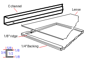 We are going with a sealed aluminum frame design.
Before we get started assembling cells lets actually plan out our frames and get things aligned right. First off, we need 2x 48" U channel mitred at 45 degrees. We also need 2x 20" U channel mitred at 45
degrees. These will make the out side frames edges. Take your Plywood and cut fit snug inside the frame edges. The edges of the 1/2" plywood will have a 1/16" x 1/2" rim around the edge and the 1/16th inch Plexiglass lens to fill out the space. You can secure the 1/16th inch plexi to the plywood and fasten the plywood to 3 of the frame edges from the underside. Seal the mitred edges with rubber cement. Using the lexan tool you can score the Plexiglass and make a clean break.
First Dry fit: With our
backings all ready we should be able to place the Clear plexiglass onto the frame and fit the 'U' channel over them for a very tight fit.
Our custom array will mount
to the roof. 14:2 electrical wire will pass from our panel through the roof at the back and down one side of the rear van frame. Now we need to turn attention to the wiring and the cell placement plans. Find yourself some construction paper large enough to make two templates. One template will be 48" x 20" and the other is 4.125" x 2.125".
Wiring path
We are going to have 5 columns x 24 cells on each 4 ft x 20” panel. By inverting every 2nd row we get + - + - + at the top with 57v – connected + and minus connected to +. along the bottom we get – connected to +, - connected to + and GND. All panels have the +57v connected together and all the GND connected together. We have two wires 57v+ and GND passing to the controller.
So here is the plan, if we
align the panel such that power is handled at the rear of the vehicle Top will actually be towards the rear. This will make it easy to run wiring down the rear frame post.
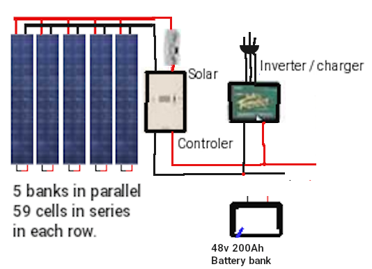 Left is the diagram of a 5 bank system used on my tricycle. Panels stacked over each other to keep them safe when not in use.
Wiring up the cell Banks
Gloves on!, make sure your area is clean and open the package of 900 cells. Grab your multimeter, A piece of copper PCB and some wood to make a
little stand. We will want to take a piece of plywood about 5" square and place a small 1"x2" by 5" along one edge and 2"x2"x5" piece of wood along the other edge of the wood square. Then place a copper shiny side up angled between the two pieces of wood block. As we check the cells we will lay the dull side against the copper such that the positive cell contacts the copper. In this way we can check the voltage and amps of each cell
easily.
The cells will have 6 positive contacts on the dull side and two negative strips down the blueish face. If you bought tabbed cells each cell will have tap wire soldered to the facing. If you bought plain cells
you will need to solder tap wire to the facing. But for now, just place the cells one at a time face up on your jig and measure with positive on the copper and negative on the face strips looking for .48v and again for 1 to 2 amps depending on sunlight.
Tap stripping the cells.
For each cell pair we need the tap wire to cover the negative strips on the face and connect to the underside positive contacts. The tab wire does not need to pass past the end of the next cell. So 2" is all you need given that each must be spaced 1/8" apart. If you bought tabbed solar panels you only need to trim the tab wires to 2".
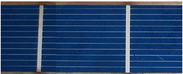
After you have got your work area setup, and tab wires cut to about 4.125" you are ready to start soldering. The soldering iron I use is
adjustable from 10-100 watts, I have it set for 40 watts. Be sure that your iron tip is clean and tinned properly, as you work keep cleaning the tip because a dirty tip will possibly contaminate the process.
You see in the picture there are white stripes from top to bottom. These are where you will attach your tabbing wires. The tab wire is not completely at the top of the solar cell. This is just to be sure it does not contact the cell that will be above it.
- First you need to use the flux pen. put a light coating of flux on that white stripe. You see the
darker blue areas, that is flux that flowed off the white stripe.
- Lay your tab wire on this stripe.
- Using a soldering point tool (or something similar) to hold the tab wire in place. don't press to hard, you might crack the solar cell under the tab wire.
- Moving from top to bottom, use your soldering iron and start soldering the tab wire down. Don't let your iron sit in one place to long, you will burn the solar cell. You will need to move your holding tool around as you move the iron down, don't let the tab wire move. Hold the tab wire down until the solder cools.
- Repeat for all tab wires on each cell.
Cell inter-connections
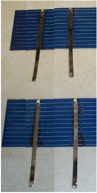
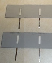 As you have enough cells tabbed to do 5 columns (119 cells) we need to interconnect them one row at a time. Remember the blue face is negative and the back is positive. The back may have either 3 contact spots in two rows or 2 partial strips.
- Flip over all the cells that need to be connected, and put flux on the white areas.
- Lay the tab wires from the top cell onto the back of the bottom cell. All cells need to connected front of one cell, to the back of the next. This puts them in series. And keep the cells 1/8th inch apart and tab wires must not extend past or even close to the ending edge.
- Solder the connections.
- Repeat until you have all connected.
These cells need to be connected in series because each cell
produces 1/2 a volt DC. We are making a 57v panel so we need to tie them in series. This is a "no load" reading. When these cells are put under a load, such as charging a battery, the voltage should drop a bit. When all series string are connected, we should see 57 volts.
Connecting cell Rows
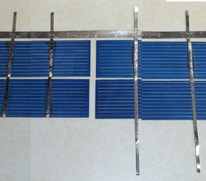 We are making 1 panel with 119 cells in series. Now I will show how to connect the columns.
As I stated before, cells need to be connected front side to back side. On the end of the string you need the 2mm tab wires protruding from the ends of the 2 strings you need to join. You can use shorter tab wires for this if you want to.
- Add tab wires as needed to the end of the strings.
- Lay the strings next to each other with a small space in between them. I would recommend doing this on the glass you will be using for the solar panel, or on something
that these cells can be kept on until they are ready to be put into a panel.
- Measure out the length you need for the buss wire. Then cut the 5mm buss wire to your measurement.
- Use the flux pen on the places that the buss will be attached. You only need to put flux on the tab wires, not both tab and buss wires.
- Line up your buss wire on one end of the tab wires. The buss wire does not need to stick out over the end, just make it even. Keep it close to the cells, but do not touch them.
- Work your way from the first one you soldered, keep the buss wire flat as you move.
- After you finish soldering, cut off any of the wire sticking out past the ends of the tab wires and the buss wire.
In the picture where the extra wire has been trimmed off you see an extra tab wire on the left string. I put that tab wire on there to test the cells to be sure they were connected. I stated earlier that cells produce 1/2 a volt, so 4 cells should be 2 volts. I was sitting under a incadescent light when I tested these cells. I got a reading
of 1.4 volts. That is very good since most cells will not work unless they are exposed to real sunlight.
Remember when testing and connecting the wires that will run out of the panel the top side of the cell is negative, and the bottom is positive.
End of strings
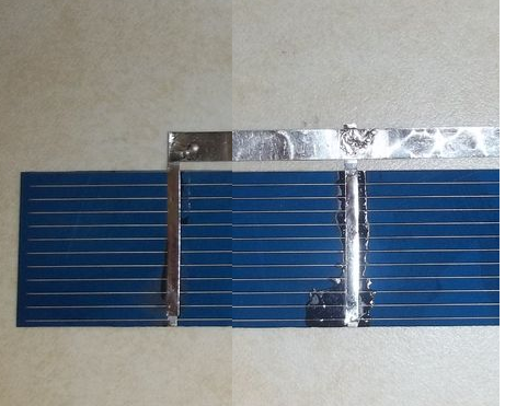 In addition to connecting strings you will also need to put a buss wire on each end of your cells (cell 1, and 39). This is done in the same way as connecting 2 strings, but you are only connecting the 2 tab wires on that one end cell (1). But on other end you are connecting all 4 wires to the buss wire. I leave a little extra hanging over on
the ones on the top. I do this so that when I add a copper wire that will run out of the panel I can fold the buss wire over the copper wire and solder it together, making a stronger joint.
The buss wire can be done before or after connecting
strings, that is up to you.
Panel assembly
With luck you have 5 strings made in series with 1/8" spacing between each cell and each row. At one end you have two buss bars and at the other you have one long buss bar. So now take your template and transfer the markings for the bottom to the plexiglass (frame is taken apart for this). I would put a center hole through the template for each of the cells and then mark the back plate where we need to put a drop of silcon sealant. remove the template and apply the sealant. Now carefully position
panels observing that you place them the right direction with the double buss bar at the top. You might want to also put sealant under the bottom buss bar. DO NOT PRESS TOO HARD on the panels or they will break.
Apply silicon sealant to
the U channel (one with the wiring holes) and place the frame piece into position. Use a 1/8th piece to simulate the lens for now. Feed a Red wire through one of the holes and extend it across to the left buss bar at the top. Strip and solder the Red wire to the buss bar. Next Feed a Black wire to the other buss bar and strip and solder it. These red and Black wires come out of each panel to be wired to the next panels red and black wires. Apply silicon sealant to the hole
inside and out to seal it from moisture.
With this done you can now assemble the top and bottom parts of the frame using silicon and the 1/8th" spacers. Remember to also put silicon sealant on the ends of the frame too. Flip the frame over and
using a small pilot hole drill 1/2" mounting holes around the frame and put in 1/2" #6 roberts screws to secure the frame pieces. Lastly slide the lens (with protective cover removed) into the frame from the open edge. Silicon and install the final U channel and drill and screw it from below. Now seal around the Plexiglass where it meats the frame. 1 Panel Done!
Charge / Discharge Control
Battery capacity
The amount of charge that can be delivered into or out of a battery, is important in the determination of available charge for use. We can measure voltage and get a very basic determination because the voltage will drop as the charge is depleted. We can measure the current being taken from or put back into the battery but it really doesn't tell us the total capacity full and how much is left. A coulomb is in the unit of 1 Ampere-second. Another way to put it is the amount of Amperes that can pass a certain point in 1 second. Because there are 3600 seconds in an hour, one amp hour equals 3600 coulombs:
1Ah = 3600C
Measurement by Voltage
We have this 3.2v Lithium cell during charge we can charge it at a maximum voltage of 4.2v at the risk of shortening it's cell life. We can also reduce the charge voltage to 4v and take longer to charge the cell which is safer. Once fully charged and the cell has had time to rest
we can measure the voltage and see about 3.2v on a good cell. If we keep monitoring the voltage and start using the cell to power something, we will see the voltage drop and can stop the cell from further discharge when the voltage reaches 0.62v. At a steady current draw, The cell will deplete faster as the voltage drops. So you can see this method is great for the cell when it's only going to be depleted near the top. So if our 48v Battery is fully charged it shows slightly more than 48v and can deliver full current until it reaches about 75% then it starts a slow decline in volts to say 45.2v. It is still delivering the current (amps) but now starts to decline faster and by 50% is now reading 37v. A even shorter time
later it is at 15% and well below 20v. To you the operator with just a voltage gauge to go by you traveled 25 miles in 15 minutes showing voltage above 45.2v. The next 15 miles you got down to 36v, and then you went another 6 miles and your battery is almost history.
Measure by Current
Years ago, automakers made the decision to stop putting analog current meters in cars because of the huge risk of electrocution by passing 60+ Amps into the dash where occupants are. This was for the time the best way to determine battery health. It allowed an operator to read
the draw of current going into or out of the battery such that if the meter said discharge 12A you knew you were at that time using 12A of power. If it said charging 12A you were refilling the battery with charge at 12A. Your biochemical computer (Brain) could kind of calculate based upon voltage and drain how far you could travel. But once more it didn't really tell you how much charge was in the battery. You know it's not like a clear water tank where you can look and see how full it is. Today, we use shunts to make measurements like this safely.
With a shunt, a very small value of resistance is placed inline with the power wires and we measure how much the voltage drop is across the resistance. Because the voltage being measured is so low and the current through the resistance is also low it is safe. We can now measure the current entering or leaving the battery. We still don't have a way to see the level of charge in the battery. We can see fluid levels but those darn electrons are too
hard to see.
We just can't see electrons
It's like they are sub-atomic. Oh my gosh that's right they are! So if we set up a clear barrel and call that a battery. Attach a hose and call
that our power wire. Put water into that hose and call that our voltage. And then depending on how fast we fill the barrel (pressure) and call that our current. We can visually see when the barrel is full. If we put a water meter inline with the hose we can measure the amount of liquid that has gone into the barrel. Then when we start taking water(voltage) under pressure (current) out of the barrel, we can again count backwards using the meter to know when it is empty.
Based on the full reading and the empty reading we can tell how full or empty the barrel is. That in a nut shell is the problem at hand. We need to count charge going in until full and count charge coming out until empty simply because we can't see how much is in the barrel
(battery).
Measure by Coulombs
We are going to investigate how the LTC4150 Measure's Coulombs.
The LTC4150 is the electrical equivalent to the liquid flow counter of the last paragraph. The LTC4150 has an output pin called interrupt, or INT for short (the line above the name indicates that this is an
"active low" signal). This line is normally high, but will pulse low each time 0.614 coulombs passes through the device (which also happens to equal 0.1707 milliamp-hours or 0.0001707 amp-hours):
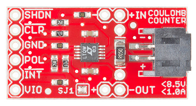
1 INT = 0.614439C
1 INT = 0.1707mAh
1 INT =
0.0001707Ah
Or to look at it another way, you will get 5859 INT "ticks" for each amp-hour:
5859 INTs = 1Ah
Keeping Track of the Charge in a Battery
As you know, battery capacity
is measured in mAh (milliamp-hours) or Ah (amp-hours). If your
battery holds 1 amp-hour when it's full, you can continuously draw one amp from it for one hour before it's empty. You could also pull 1/2 amp for two hours, or 2 amps for 1/2 hour, etc.
Using our favorite tool the computer we can enter the maximum capacity of the Battery pack in Ah (Amp-hours). We can then monitor the ticks and
direction from the device to add or subtract from the full capacity. Compute the two values in real time to inform us how full the battery is. It has more implications than that too. When charging the value can tell us when to absolutely stop charging so as not to overcharge the battery. It can also tell us when we can't go any further without damaging the battery.
Because it measures amp-hours as you're using them, the coulomb counter makes it very easy to keep track of your battery's state-of-charge (how full it is):
To use a coulomb counter you need to use it with a computer and the people at sparkfun
have developed a circuit board for just this purpose that can be used with the Raspberry Pi computer, Ardunino controller and other such devices.
First, assuming you're starting with a full battery, set a variable to your battery's
initial state-of-charge (e.g. 1000.0 mAh).
Listen for the "tick" (low) signals from the INT pin. Each time you detect a tick, check the direction signal, and add or subtract the above per-tick mAh value (0.1707 mAh) to your battery-state
variable.
Head on over to https://www.sparkfun.com/products/12052 for a complete run down on the use of the coulomb counter and sample code for the Arunino type controlers.
For battery sizes greater than 1 Ah you would adjust the number of ticks to # of Ah * 5859 ticks. So 2Ah = 11718, 20Ah = 117180 ticks and so forth.
* Note that in real life it takes a bit more current to charge a battery than you'll later get out of it. This is because the chemical processes that store charge aren't 100% efficient, with the excess turning into heat. The amount of loss varies depending on the type of battery, charge rate, age of the
battery, temperature, etc. You can account for this by providing a manual "reset" input when the battery is fully charged, or doing some calibration to see how many more ticks you get when charging vs. discharging (though this will change with battery age, temperature, etc.).
Bonus: Determining Average Current
An additional (and entirely optional) trick is that if you keep track of the time delay between "ticks", you
can back out the average current used over that period. The equation is very simple: mA = 614.4 / (delay between "ticks" in seconds)
Note that because this number is the average current use over the time period, the instantaneous current could be higher or lower. This is also covered in their example code.
Connecting the Hardware
The LTC4150 Coulomb Counter IC has a very simple interface. It has an INT (interrupt) output that is normally high, but will go low when a given amount of current has passed through the device. There is also
a POL output that tells you which direction current is flowing.
Max Ratings:
The Coulomb Counter can
accommodate power sources up to 8.5V, and currents up to 1A. It works particularly well for single-cell (3.7V) Lipo batteries, LiFepo4 (3.2v) up to 1000mAh.
So on their site, they explain the straight forward way to connect this handy device to the Arduino using it to power the board (IN & GND) and the passing of signals from the counter (/int & POL) and
from the controler (/Clr & /ShtDn)
Under this scheme, The battery source goes to the input (IN) and the load connects to (OUT). If using a charger as well to count both charge and discharge the charger goes on the (OUT) side.
But my Pack is 12v @ 20Ah or 48v @ 100Ah
Traces on the board and the LTC4150 can't handle more than 8.5v and / or 1.6A so what can I do now? They say there is no easy way to handle higher values more easily, but, and there is always a but, it can be done. But first lets talk about Interrupt vs Polling. Using interrupts is fast and assures the most accurate counts where as Polling means you check it at intervals and hope not to miss counts. To poll the
device you need to open the SJ1 connection so that if an int occurs it stays low until the CLR is pulsed low. If your code is too slow to react you will miss counts under polling.
By default, the Coulomb Counter is set up so that the INT output will go low and immediately return high. It will only be low for a few microseconds (millionths of a second!), which is enough for interrupt-based code to detect the falling edge, but random checking will almost certainly miss such a brief signal.
Wiring the Hardware
Here are the minimum required connections for the example sketches.
If you want to try the interrupt example code:
Leave solder jumper SJ1 closed (the default) You will need to connect (at least):
- VIO to VCC
- INT to D3
- POL to D4
- GND to GND
If you want to try the polling example code:
Open (clear) solder jumper SJ1 (Instructions)
You will need to connect (at least):
- VIO to VCC
- INT to D3
- POL to D4
- GND to GND
- CLR to D6
For EITHER version of the code:
Ensure that SJ2 and SJ3 are both open (clear) for a 5V
Arduino, or both closed (soldered) for a 3.3V Arduino.
Downloading the code
The example code is maintained at the Coulomb Counter BOB Github repository. You can download a ZIP file of the entire repository (or clone it to your computer if you have the github software installed),
or save the sketches directly.
Changing the Sense Resistor
The Coulomb Counter uses a sense resistor to measure current. This very small resistor (0.05 ohms) is the only component located between the input and the output. The LTC4150 measures the voltage drop across this resistor; thanks to Ohm's law the voltage drop is directly
proportional to the current passing through the resistor. This
resistor is known as a shunt. Just like automotive ammeters of years ago, shunts were used to govern very high battery currents to display on very low current meter movements. And this shunt gives us a new way to use the LTC4150
In real life applications you can go with a 0.0002 ohm shunt to achieve 250A in 5859 ticks which means 1 tick for each .042A. But this is untested by me.
Using ohms law you can determine what current flow is through the measurement of the voltage drop across the resistor. As such, if 1v is dropped across a resistor of a value of .05 ohms the current through that
resistor is 1/.05 = 20A, changing the resistor to .0002 ohms would drop the voltage under the same 20A load to only .004v. This is why lowering the value of the shunt resistor works with the current PCB.
* Note that the PCB traces on the board are not designed
to handle more than 1.6A continuously, and the JST connectors are not designed for more than 2A.
They state there is no easy way to increase the maximum supply voltage above 8.5v and this is partially true. Typically you make measurements from supply to ground return. This is 8.5v maximum in this case. But if we employ level datum shifting we can accomplish the same thing. Suppose we have a 384v dc Battery in an EV and we want to count the coulombs with a potential draw of 250Amps. Obviously this little board would get fried if you tried. But get this, a 5V zener diode #NZX5V1B_133 in series with a 75k ohm resistor raises the datum such that the board sees only 5v and the board is happy. It has no idea that the 5v is being taken from the 379v(symbolic gnd) and the 384v supply. Now using a opto isolators device that is suitable for mismatched voltages and currents we can relay the ticks from our 384v system safely through optics to our 5v computer system. We can also control the device the other way. The 75 ohm resistor in this case would need to be a 20watt because of the current and voltage it is having to dissipate. The preliminary layout
shown later does not take this into account. To handle this situation the high wattage heat generating resistor would need to be mounted off board.
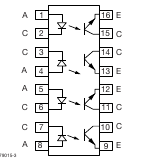

As can be seen here the ilq2 quad opto isolator has 4 distinct units in one 16 pin dip package. on the photo diode side we just need to place a bias resistor to either the plus or negative rail and supply our signal to control active high or low accordingly. This would be
supplied by the int pulse. The microcontrol side has a similar bias to it's much lower voltage source and receives the int signal to the microcontroller. The same is true for the pol signal it senses the direction of current and tells the diode to go high or low and the Phototransistor side tells the microcontroller what the result is. For the other two signals we need to go the other way. On the computer side we use the same biasing as we did before and supply the CLR and SHDN signals to the diode and with same precision pass that
information onto the high voltage side using the Phototransistors to relay the results to the board. Resistors 2 thru 9 are selected to sink 5ma so to meet with device specs they are all 750 ohms 1/4w. And here we have the daughter board that accomplishes the task with ease.

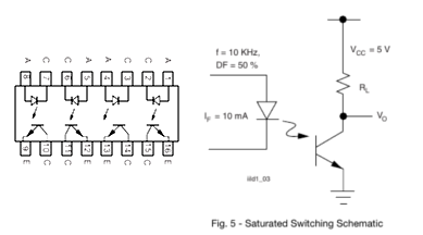
In the above we have not removed the on-board shunt yet. The blue wires patch our off board heavy shunt resistor onto the Coulomb Counter. The boards interconnect with ease.
An understanding of the ilq2 IC. Shown is the chip layout and the represented circuit. Both the diode
side and the phototransistor side have resistors pulling the inputs high. They also have cathode (diode) and emitter tie to ground tags. BUT these positive rails and negative rails are NOT the same. On the computer side the plus 5v and ground are that of the computer. On the high voltage side, Plus 5v is actually 384v and ground is a SYMBOLIC ground 5v lower than the 384v. R1 determines the voltage drop value and current supply at 379v @ 50mA. The Zener diode assures the potential difference is 5v at all times.
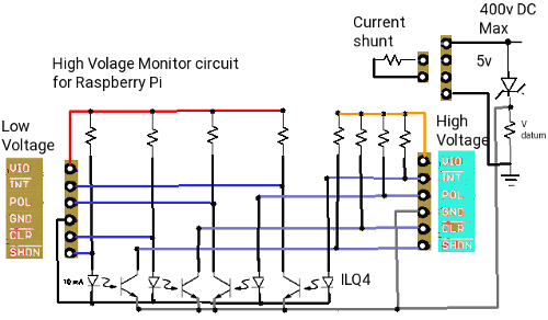 The board is simple having 1 Zener diode, 9 resistors, and a ilq2 quad opto coupler IC. Besides the connections made from the coulomb board to the daughter board, we have just 5 wire pads to connect the external Shunt to the coulomb counter and our computer connects to the 6 pads of the new board instead of the coulomb board. Problem solved.
As designed the daughter board add-on can work with up to 500v and depending on the shunt resistor up to 600 Amps. Because we are Level shifting from the high voltage supply, The board can be used for any voltage from 10v to 500v. The LTC4150 will always see 5v as it's supply. R1 is sinking 379v @ 50ma so it's value is 7.58k. If you supply only 10v as a supply this would reduce current to only 65ua so the value picked would need to be smaller, like about 100 ohms. The shunt resistor on the coulomb counter board must be removed if doing high voltage. The shunt resistor you will be adding to the daughter board high voltage contacts must be selected such that for 384v a shunt of .0002 ohms will produce a voltage drop across it 50mv and a current of 250A. The shunt resistor would be a maximum of 30w
From the original published specs of the Coulomb Counter They are saying it can count 1A based upon the 0.05 ohm shunt. This addresses that the coulomb board is measuring a voltage drop of 50mv. This modificaton means that instead of getting 1 tick every .0001707 Amperes you will see 1 tick every .04 Amperes which for a high current supply under high demand is still quite useful.
Side note for those who are worried about close proximity of 384v to 5v this a real non-issue. We are taping 50ma from the 384v Battery pack and due to the Zener we are using 5v for control on both sides even though the 5v potential on the high voltage side is taken from the top of the 384v rail. the device is rated for 10 mA with isolation up to 4Kv. That isolation is almost 1000 times what we may see in the worst case.
Special note here. When you start to move there is a half cycle surge up to 25 times the motor current draw. The motor maximum run current is 10A but during initial start it can have a 200A spike for about 0.00833 seconds. That is why we
planned in for 250A. The slower you start to move the less surge you get which can extend your range substancially. Once the vehicle is in motion you can apply more acceleration.
Using the SHDN Input
You can reset or shut down the LTC4150 by making the SHDN input LOW. This will reduce the power consumption of the board, but the LTC4150 will not measure current consumption in this mode. This input has a pullup resistor; if you do not need shutdown functionality, you can leave this input disconnected. Refer to the LTC4150 datasheet for information on resistor selection. There is also a spreadsheet in the Github documentation folder that may be useful.
Use in an EV Motorhome
The Battery banks for the motorhome will be 384v @ 84Ah minimum. The datum resistance needed must drop 50mA @ (384v-5v=379v). The resistance value is 7.58K ohms @ 20watts. For the shunt, we know that 5859 ticks = 1A because each tick is .0001707A using the original
design. Our Pack voltage is 384v with capacity of 168A. Under charge it is getting 37A and under discharge it is drained by up to 10A with surge of 200A. We can't use the original design specs of .05 ohms because at surge time that would result in 7.5v which is 150 times the maximum potential of the chip. The shunt must be reduced in value. 0.05v / 250A surge = .004 ohms. We also need to control 3 related systems while tracking the charge and discharge. As such we made a special charge control for our motorhome.
EV Charger
The charge controller takes direction from the coach computer and the AC charge port. The computer provides 4 enables (battery pack 1, battery pack 2, Solar, and AC charge). At the AC charge port there is a microswitch that is activated by inserting the plug into the port. When AC shore power is plugged in, it converts 120v AC to 60v AC and if the computer has issued a 'charge-enable'
signal passes that AC voltage on to a full wave bridge rectifier to produce 57v DC for charging. As long as the AC charge cable is plugged in normal vehicle operation is prohibited. The 57v used for charging has 37A of charge current. As it passes through the coulomb count circuit, we have .00034 ohm x 37A = 10mV and since the coulomb counter is measuring the voltage drop in mV it can adjust the ticks
to match.
Roof top solar panels supply power when there is sufficient sunlight also to the charging
system. It can also be enabled/disabled from the computer. When solar charging the counter again is measuring charge in mV from the drop across the shunt. The 2 battery pack enables determine which battery pack(s) to use. Each has a contactor run by the enables. During drain to run the vehicle, a second coulomb counter notes the direction change of the charge to be discharge and counts ticks of current going the other way.
The limits of the 120v shore power is 15A at source to provide 37A at the Battery packs for charging. The solar array provides 10A or more. The size of the battery Packs and their current state of charge governs how long charging is going to take. Taking the case of a 300Ah pack and 30A shore charge, it will take just over 10 hours from empty. Using shore and solar would reduce charging to 7.5 hours. But, and there is always a but, You can't discharge the Battery Packs less than 20% or they will be damaged. They also can't be charged to more than 98% so full charging range is 234A or 7.8 hours using AC shore power. Using both shore and solar cuts charge time cuts to 5.8 hours. If we do as
planned to use 2 packs of 144Ah for charge times which will be longer. One last contingency is the solar charge while parked between trips. During time you are parked or stopped, the solar can charge at 10Ah while you dine, shop, or work at a job. So assuming you drove to work and used 120Ah from the packs and solar charged for 8 hours while at work, you effectively only used 40Ah. When you get home total use was
160Ah so your charge time becomes 5.3 hours on shore power. Costs at 0.15 per kw means it is costing 0.27 per hour for charging. 7.8 hours to charge to full is $2.10, 5.3 hours is $1.43. A substancial difference from $20 to $40 a day for gas.


All connections to the charge controller are on one edge. A 10 wire connection goes from the controller to the dash computer distribution pcb. A microswitch at the charge door connects next followed by the 3
wire AC 120v connection. The power wires from the roof top solar array connects next. Then we have the 48v power to the automotive function board and two sets of Battery pack connection. There are two off board parts. A terzoid transformer is one and the Shunt Resistor is the other. The shunt resistor is due to size and heat it produces and the transformer is just due to size.
EV Battery 101
Choice of cell types
Batteries lie as the source of
energy to power the EV. The type and configuration of the Batteries determine the potential of project design. Below are the specs for the four common lithium cell types. While all four can be combined to make the Banks or packs, the cell size and availability are the determining factors to project success.
From our the chapter on the chassis and Battery specs we know we have 1844 lbs to 2198 lbs for battery Pack. We want 2 Banks to a Pack and 8 Gcells per bank. The Gcells will contain 15 cells in series and 7, 14, or 24 cells in parallel to give us 42A, 84A or 144A Gcells. Having just 3 Gcell types 48v x 42A, 84A, 144A gives us 10” x 10” x 6” , 10” x 10” x 12” and 10” x 30” x 6” sizes suitable for any size of vehicle. Gcell weights of 34 lbs, 68 lbs or 115 lbs. All using 32700 cells. So read on to see how I worked this out.
In this chapter the term cell or battery refers to the individual cells like items 1,2 and 4. Gcells will refer to the 3rd type below as a Gcell that is really a group of type 1,2, or 4 arranged into a single larger device. A Bank is a group of Gcells and a Pack is a group of Banks. In my design of battery packs I always have 2 interchangeable banks. An MBank is where multiple banks of Gcells are connected in parallel to take the place of a single bank such where we might have a 42A bank and 2 banks per pack for a total of 84A we can instead wire 2 banks together as an Mbank thereby effectively doubling the pack to 168A
and have just 2 mbanks.
 |
The 18650 was the original cell of choice for EV at 18mm x 65mm providing 800 to 1500mah. $5 to $12
The 21750 is the new choice at 21mm x 75mm with 5000mah $16
The 32750 is my preference 32mm x 75mm at 6000mah. $10 is the cheapest cost of the 3 and although it is bigger and heavier, when your talking about 1000’s of cells to make a pack the cost savings are significant.
Consider this:
To make a 384v 144A bank with 2 banks to a pack we need 120 rows in series by 144/cell Amps in parallel per bank with banks then placed in parallel.
- 18650 cells = 2 x (120 x 96) = 23,040 cells $276,480 2142 lbs
- 21750 cells = 2 x (120 x 29) = 6912 cells $110,592 691 lbs
- 32750 cells = 2 x (120 x 24) = 5760 cells $57,600 1843 lbs
|
So in the above we are targeting 384v @ 288Ah. If we run 8 Gcells in series we get the 120 cell value making 384v. Each Gcell has 15 cells in series and a different quantity in parallel such that the Gcells vary in size weight and price. Gcell Length is 5.6” for 1), 8.4” for 2) and 10” for 3). Gcell width is 4mm smaller for 1) than 2) or 3) but height becomes 67” for 1), 26” for 2) and 30” for 3) and you saw what happens to weight and price.
Factors to consider in converting a vehicle into an EV is really weight vs cost vs range in miles. We will remove:
- Gas tank sizes vary so we will just use 80gal so fuel weight is 500 lbs + tank at 35 lbs
- engine 735 lbs
- transmission 135 lbs.
- exhaust system 85 lbs
- 5 x lead acid battery 425 lbs.
- fresh/waste water 500lbs
- doghouse 60 lbs
- Hot water tank on propane 60lbs
- about 10 lbs of dash equipment like instrument cluster, & radio.
So when we convert a vehicle we are reducing curb weight by ~2535 lbs. Then we add back the motor, inverter, and digital control center 140 lbs. So we are ~2395 lbs lighter in curb weight at this point.
If we use 21700 type cells a 145A Bank is 3480 cells for $55,680 and 313 lbs.
Using 32700 cells is a 144A Bank with 2880 cells for $28,800 and 921 lbs.
The number of cells and cost per Pack is drastically reduced and still leaves us with-in the weight margin. That is why I chose to use 32700 cells for the off the shelf Gcell Batteries for all converted to EV vehicles. And if the auto manufactures would adopt this same concept all vehicles would be more friendly on the pocket book.
Curb weight does not include driver, passengers, cargo on cars and trucks so we can’t use curb weight to define range. On a motorhome as outlined here, GVWR is listed at 17500 lbs. So this tells us the maximum weight and we can figure that since a motorhome is our home it has all our belongings. So we deduct GVWR-Removed items= available for additions = 2395 lbs. Miles of travel is = Kw/(GVWR/10,000) with Kw = V x A so with 384V x 288A = 110.592Kw.
Total distance in miles = 110.6/1.75 = 62.8 5 miles
(104km) between charges. If we pull a car behind us the distance of travel = 110.6/2.40 = 47.04 miles 76.74km). As long as we are just traveling Alberta where campgrounds are 70km apart we can hop from campground to campground stopping over long enough to recharge before making another jump.
Recharge times per bank (1152A/8 Gcells per bank = 144A) *not all campgrounds charge for power
- 15A shore power = 1152A/37A=31.5 hours $0 to $25.57 @ 0.17 per kwh
- 30A shore power = 1152A/74A=15.75 hours $0 to $25.57 @ 0.17 per kwh
- Solar charge = 1152A/19A=7.5 days because sun is out maybe 8 hours a day $0
Because we have 2 banks the charge times double. Once charged back up (2 to 3 days) we can stay and camp there or make our next campground jump. Although we are 285 lbs over weight our chassis spec on the GVWR includes 500 lbs of fresh water, waste water so if we dump all tanks before moving we are under weight by 215 lbs. Adding 19 x 1A to 2A solar panels 180sqft at 2.5 lbs/sqft=450lbs. So our maxed
out Motorhome with 76km range will be 17285 lbs without solar and 17735 lbs with solar. The GCWR remains at 24,500 lbs. We can pull a trailer with car on it if under 6265 lbs or a four wheel down car 6265 lbs. But when all is said and done we have few options.
For EV to work we need replaceable Gcells 48v @ 42A for cars and trucks, 48v @ 84A to 144A for larger vehicles like motorhomes. The Gcells would be 34 lbs or 68 lbs or 115 lbs each respectively with size of 10” x 10” x 6” to 10” x 10” x 12”. 8 Gcells per bank and 2 banks or more per pack.
|
Gcell Planner |
|
| Volts |
48
|
|
|
|
|
In series
|
8
|
|
|
|
|
Banks |
|
|
|
|
|
Pack volts |
384 |
|
|
|
|
Gcell Amps
|
Gcell Weight |
Length |
Wide |
Height |
Gcell Cost |
42 |
34 |
10 |
6 |
10 |
$1,050.00 |
84 |
68 |
10 |
12 |
10 |
$2,100.00 |
144 |
115 |
30 |
6 |
10 |
$3600.00 |
Bank Amps |
|
|
|
|
Bank Cost |
42 |
272 |
10 |
48 |
10 |
$8,400.00
|
84 |
544 |
10 |
96 |
10 |
$16,800.00
|
144 |
940 |
30 |
48 |
10 |
$28,800.00
|
| Pack Amps |
|
|
|
|
Pack Cost |
84 |
544 |
20 |
48 |
10 |
$16,800.00 |
168 |
1088 |
20 |
96 |
10 |
$33,600.00 |
288 |
1840 |
60 |
48 |
10 |
$57,600.00 |
Our proposed battery packs for cars mini-vans and suv’s for commuters would be 2 banks of 8 Gcells, Each Gcell would be 15 series rows x 7 cells in parallel.
Each Gcell would be 48v @ 42Ah and Gcell weight would be about 34 lbs and cost $1050.00 . Range between charges would be 70 miles with 4 hours charge time per day if driven 32 miles a day. Charging costs $2.39 a day compared to ICE at $6.07 a day if 30mpg. Savings over 15 years $20,148 - $16,800 for new batteries = $3,348.00 for vacation! (does not include interest on savings).
People needing higher ranges could pair up banks in parallel such that banks become 2 banks of 2 mbanks (4 banks wired with 2 connected together as one).
32750 cells = 4 x (120 x 7) = 3360 cells $33,600 1074 lbs range 140 miles
32750 cells = 6 x (120 x 7) = 5040 cells $50,400 1611 lbs range 210 miles
The problem of doing this is that the weight is too much for small cars and mini-vans. MIdsize cars and light trucks might be able to handle 1) above, but only full size cars and ¾ ton Trucks or larger can do 2) above.

Remember that the auto industry wrongly specifies GVWR by curb weight which excludes passengers and cargo. The mini-van curb weight was 3460 but had a GVWR of 4430. The GCWR of the mini-van allowed for a trailer of 3000 lbs so technically, because it’s GCWR listed at 7400 lbs we could attach a 3000 lb trailer with capacity for 2100 lbs
and use 537 lbs of that to add additional battery banks. Thusly, bank-A now has the onboard bank and the satellite bank-A in parallel and doubles Amps to 80A. Bank-B now does the same and our range almost doubles during run. Our GCWR now comes into play. With GVWR of 4430 + 3000 for the trailer we are now at 7430 GCWR we have now got 61.44Kw so 61.44/0.743 = 82 miles instead of 70 miles if the trailer is full. We gained more range by adding battery banks but lost range because cargo space increased by 1600 lbs or more. If the trailer
costs $1,400 and battery banks cost $16,000 our range increase of 10 miles cost us $17,400. On the other hand, if the trailer only has the battery banks, GCWR is 5867 and 61.44/0.5837 = 104.72 miles.
Battery Pack health
Cells decline and fail at different rates. As cells in use go through life they start taking less charge as they age. In a one pack does all this can mean that if rate of decline results in say 10% of original distance the answer is to replace the whole pack for $16,800 for example. But because we are using Banks, If only 1 bank has declined
rapidly, we can replace the bank $8,400. Our banks are 8 Gcells that are individually replaceable so narrowing it down to a Gcell now results in $1050 as cost of repair. The
user can now replace their own battery Gcells just like we do when our lead acid wet cells need replacing. An $85 wet cell is 80 lbs and sits on store shelves. With standardization we can have stores stock our 34 lb Lithium cells on the shelves for $1050 each. Environmentally, we are moving away from harmful lead acid in favor of recyclable lithium ion.
Just like with lead acid where we turn in the battery for core charge so it can be rebuilt, the gcells can be rebuilt. Open the Gcell and extract the micro-cells (4 x 12v micro-cells) = 1 x 48v Gcell. Disassemble the micro-cells (tapping strips go for cycling), cells in good shape maybe reused, poor and bad cells go to final recovery.
Gcells get rebuilt from new cells and new tapping wire. Reusable cells may go into games, laptops, flashlites etc where shorter lifespan is not so critical.
Because we have almost all cars, truck, suv’s using 12v systems and the 4 x 12v micro-cells make our Mini-packs (Gcells) we need to bring the 12v junction out as a 3rd terminal on each Gcell so it may be used in the first position of each bank.
Resale and recovery value
People have two options maybe more when it comes to vehicle recovery value. The Motor, Inverter, Electronics, and Battery Pack are totally salvageable from a wreck or worn out car. It is unlikely that the insurance will offer you much. That 2000 malibu which the insurance writes off at $2200 as a gas vehicle will likely still be $2200 as an EV even though you have $17,000 invested and only used up 1 of 15 years life. The true value is $15,866 + $1000 for value of body. A better choice is to buy it back as salvage $50 remove the Motor, Inverter, electronics, and Battery Banks for reuse in your next vehicle or resell them and scrap the rest. On the other hand you want a new or different car. The auto lots are
not your friend.
They understand ICE, that looses $2000 the minute you leave the lot. An MRSP of 30,000 = 30,000 – mileage/10 – 2000 so if car is over 280,000 miles it has trade value of 0. Another vehicle with same MRSP with 80,000 miles might be worth $20,000 trade-in if not too old and in great condition. This is because ICE has lifespan of 300,000 miles but an EV has lifespan of 1,000,000 miles on EV part and 300,000 miles on the body. If you decide to sell privately you will need to show records proving how long the batteries were in use which includes odometer at battery change and current odometer.
The whole industry is in for a shake-up if all vehicles have to be electric by 2040. 24 million vehicles in north America will have a value of 0 in 2040 unless they are electric. A look at the ford lightning F150 vs F150 gas reveals, $51,000 vs $38,000 ($9,000 is value of ICE parts) so $32,000 is their claim to EV over the $29,000 chassis. The specs aside from some bells and whistles claim 10,000 lb towing on the EV vs 14,000 towing on the ICE which is 1100 lbs more than my research showed. Range was stated at 230 miles to 300 miles vs 450 to 550 miles but they leave off the Kw of power so I have a hard time calculating true Battery Pack
specs. $32,000 suggest a 4 bank equivalent = 160A and presuming they are using 384v standard that says 61.44Kw, they
don’t give the GVWR or GCWR but if we use my figures 5580 lbs that says 61.44/0.558 = 110 miles not 230 to 300. To attain their figures we need 350A of battery. 8400 cells @5A 21700 cells at $3.81 each which is possible if buying in bulk like an auto maker does. For our concept we would have 35 cells in parallel x 15 cells in series per Gcell, and 8 Gcells in series per bank with two banks.
To enclose such a Gcell you want it to be safe for operators, ventilated, short proof (conductivity safe), and reasonably light. Our Motorhome Gcells are 17.28 lbs each. The 48v cluster is 259 lbs and our bank is 2073 lbs with total pack weight of 4146 lbs. This creates a big problem. For 100 mile range we are 2303 lbs over weight when towing a car and still 1137 lbs over weight without the car. Cutting the range to 50 miles (83 kms) removes 1 bank worth of weight 2073 lbs. This means we are 230 lbs too heavy towing a car and 936 to spare without the car.
The safest Packs are those with:
- Plastic or fiberglass structure so
that people can be kept away from extreme energy supply..
- No Exposed High voltage or high current connections
- Metal re-enforced to withstand weight and also to protect from road hazards.
- Not too heavy to be managed.
- Easily mountable.
For very practical reasons, each
bank needs temperature monitoring and control, Voltage Balancing, Charge balancing, State of Charge, State of health, and functional control. BMS is the go to method of protecting the battery banks. It isn't as straight forward as they lead you to believe. Yes the BMS protects the Battery from over voltage, over current, over temp during charging and shuts the whole process down if it encounters any such condition. It can jump in if there is a short circuit so as not to damage the battery. Under live operation, BMS is both good and bad. It tries to balance all batteries to be at the same voltage
either passively or actively. But voltage does not have much to do with it compared to SOC, SOH When one cell reaches full charge BMS stops charging all cells it is in control of. When one cell reaches maximum depletion, BMS cuts all it's cells out of circuit. Not what you want at all in an EV application. So we need to investigate what will work best and safest.
Making custom Gcells from cells
The cells that are used to make up Battery packs come in 3 basic styles and a multitude of Amperages and qualities. China produces the least
expensive but also the poorest quality cells around.
Our target will be high quality 32700 liFepo4 cells rated for 6A per cell.
Gcells are commonly made of blocks of 2x5, 3x5, 4x5, 5x5 or combinations of them. If you need 12v then you need 4 series Gcell-blocks. For 24v you would have 8 series Gcell-blocks and for 48v you would have 15
series Gcell-blocks. Note cells are 3.2v and a 12v battery is
generally a 12.6v to 12.8v battery. By the time you make it to 48v, 16 blocks would make 52v not 48v. But 15 blocks works out to 48v precisely.
Each time you combine another cell in parallel the current goes up by the cells current value. Always keep cells with-in each Gcell-block of the same type and rating. A 48v 200Ah Battery would take 15 series
pack-blocks of 34cells at 6Ah in parallel. So each Gcell needs 510 cells. Each of the Gcell-blocks would be 8rows x 4cells and one row of 2cells. (~9" x 4" x 2.5"). The whole bank would have 5 Gcell-blocks x 3 Gcell-blocks (27" x 20" x 2.5"). The weight of the bank is about 163.84 lbs.
This design seems more feasible with 4 micro-cell blocks in an 19” x 11” x 3” shape or done as 10” x 10” x 6”. Add a 16 pin connector with pins 1 to 15 going to each (-) and pin 16 going to +48v and we have BMS ability.
1 bank would be 10” x 10” x 48”
So it's time to look at the equipment you will most probably need to make battery packs.
And the supplies you will need to make battery Packs
Until you have all the equipment in place there is little
need to start on the project.
The Spot welder is the first and most important thing needed to make battery packs. Heat from soldering irons can damage the batteries fast so avoid doing that!
Make a simple battery pack
 You have some up front decisions to make about the pack you are about to make.
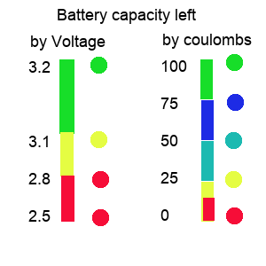

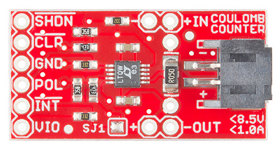
Capacity methods
Coulomb counters check Amps
Cell loggers check voltages
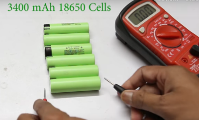
Fully charge all batteries and let them rest for
a least 5 minutes then measure them so that you make sure each row
has identical voltage. Ideally you also need to chart internal
resistance and here is how.
Internal resistance
Make a spreadsheet for your cells. For each cell measure the open voltage and record it. Pick a resistor and record it's read value. Put the resistor across the cell ends and measure the voltage across the known resistance. Record this next to the battery it refers to. V=IR so I=V/R. With the now known voltage across the resistor and known resistance we can calculate I. And knowing I, we can use (Vopen -Vload) / I = Rinternal. So for each cell record the Rinternal. Any cell with a high internal resistance will not work well in a Gcell. Are you sure you can trust a Gcell was
tested properly and balanced properly before you got it?
Before you begin making the packs it is important to closely measure the voltage of each cell and group them such that all cells per Gcell read the same. All cells in a parallel bank will gravitate towards the weakest cell's voltage. This makes it difficult for the
BMS to level out the batteries consistently. You also need to verify the internal resistance of all cells to be in a parallel branch. This is done by measuring a resistor accurately and record it's resistance. Then place the resistor across the cell terminals and measure the voltage with the resistor added. Subtract the voltage with resistor from the open circuit voltage to get the voltage drop. Compute open voltage /Resistance (R) to get current (I). Calculate
Internal resistance as Voltage drop x I . Any cells with far out of line internal resistance should be allocated to some other project not critical.

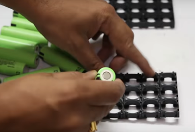 Build your forms to accommodate the Gcell arrangement. In our case for a 10” x 10” x 6” Gcell we can go with 8 cells x 7 cells x 2 forms and 7 cells x 7 cells x 2 forms. For 32700 cells the forms are 1x2 or 1x3 but for 18650 the forms are 1x2 1x3 1x4 1x5 and even more types. If we connect 2) 1x3 and 1) 1x2 end to end and do 7 rows of
that we have 1 form made. We repeat form 2, then connect 2) 1x2 and 1) 1x3 end to end and 7 rows of that we have form 3 made and repeat for form 4. Observe polarities ! All 7 columns in a row must be all (+) down or all (+) up. Row 1,3, 6, 8 should be (-) down, with Row 2, 4, 5, 7 being (+) down.
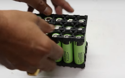
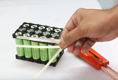
Once all cells are in place secure the top frame. We now need to cut tapping strips in Preparation to wire the cells. Remember these cells
are fully charged.


We will connect all (+) in each row together (Parallel) and connect short Tapping strips between (+) and next rows (-). Row 1 (-) also gets all 7 columns connected. Each (-) row gets a Tapping strip with a wire on for the BMS and row 1 (-) get heavy wire to (-) terminal, Row 5 (-) gets heavy wire to (+12v), Row 8 (+) goes heavy wire to Row 9 (-), and row 15 (+) goes heavy wire to +48v
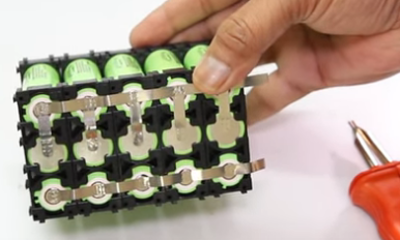 This example shows (+) row with all columns connected in parallel and in series with next row. In this example row 1 (-) is (- pole), row 1 (+) has (+3.2v) . Row 2 (+) connect all (+) together and all (+) wire to row 3(-). And row 3 (+) all connect together and a wire to (+9.6v)
as this is a 9.6v Gcell with a 3,2v tap.
To split or not to split
When it comes to high voltage
battery there becomes a very difficult problem. We have 15 cells in series and 7 cells in parallel to make 48v. The BMS needs to monitor each series cell row to balance them. Then we take these 48v gcell blocks and connect them in series to create the 384v bank and then connect two identical banks to make the 384v pack. Our most economical charge source is 57v such that we can charge direct from solar and / or convert 120v AC to 57v DC and charge from a shore line. Converting 57v to 420v DC to charge a 384v DC pack is extremely
expensive and quite loss prone. Manually disconnecting 48v blocks so they can be charged individually is time consuming and potentially hazardous. So I needed another approach. the 48v blocks are in series during vehicle run operation but, and there is always a but, what if we electronically convert the series blocks into parallel to charge them.
Enter the MOSFET it can handle high currents and can be switched on or off with a low voltage signal.
 High power mosfets like the irf540 N-channel can handle the high voltage and current in the arrangement but, and there is always a but, it take 2 mosfets to replicate the triac due to properties of the diode body of the mosfet. The layout above is using the mosfets. Two
mosfets are used between each battery block and between the first and last battery block and the +384v and traction ground. So we have 18 Mosfets. Then there comes connecting the (+) and (-) of each battery block to the charger. The mosfet uses 4 per battery block. This description is for only one bank. We need to do this on both banks.
So we have 48 mosfets per bank. To save us from a PCB size nightmare and wiring nightmare, we can connect 6 Mosfets to each 48v block along with the BMS so that now we have 16 wires confined with-in each block for BMS and a simple (+) and (-) (En) (Chrge) (chrg+) (chrg-) passing from block to block. Special note: During RUN system
ground = Run ground and charge ground is disconnected. During charge, system ground = first 48v block ground, Run ground is disconnected and charge ground connects to all block (-).
 Ignoring the right hand side of the schematic above, (BMS part), we have the new 48v switching circuit that will be at each 48v block. Prev-grp applies only to the first 48v group and it connects to RUN GND. Q4 and Q5 are used to connect or disconnect RUN GND to Block (-). On all
other 48v blocks Prev-grp Q4 and Q5 aren't used. En chooses connect or disconnect blocks. Block (+) and (-) connect across the 48v block terminals. Chrg (+) (-) are the charging source and they connect across the block terminals when grp-sel is active. Block (-) connects to Next-grp of the previous block.
So back at the computer, it is told to charge the cells by the operator (you). It sees it has 94,000 ticks (5958 ticks per amp) or 15A left. It knows the pack is 120A or 714,960 ticks when full. So it selects Charge Enable and unselects Drive Enable. At the battery pack, all
Mosfets between groups of 48v stop conducting. All Group gcells connect to charger in parallel on both banks. Each time .00017A goes into the battery group, 1 tick occurs and so the computer adds 1 to the ticks. When the ticks add up to 714960, the computer unselects Charge Enable and selects Drive Enable. Back at the batteries, all gcells return to series and are disconnected from the charger. When all is done the computer looks to see if the operator selected shutdown when charged or not. If shutdown then turn off everything
otherwise switch to main screen and wait.
Since the topic of high currents of the battery packs has been mentioned often, we need to address it. Lets say our Battery source is 384v @ 288A like we have. From the research on handling high voltage and current they make a very valid point. It is highly dangerous to have a power source over 100A continuous and in many jurisdictions it is even criminal. Most people own a car of some sort. It has a battery that is usually 65Ah or higher and this battery also has another rating 800 to 1500 CCA which refers to cold cranking Amps. Since the CCA is used only during the starting, it is deemed non-continuous and safe. Our 288A pack follows the same guideline. During the first half cycle 1/120th of a second at motor start it draws 200A but then draws beteen 0 and 10A depending on load and speed. It's kinda like if we directed all water from Niagra falls into your shower at home. Use of the whole all at once would drown you but using a tricle is enough and great.
The DIY sites abound and talk of 600A to 1000A systems. They are talking about the current used over the whole range to travel not the typical current draw at a moment in time. If it were over a moment in time the maximum range would be maybe 2 miles. It is over the whole range. so if you have 56 mile range, and it uses 560A to do that range, you are using 10A per mile. and if you are doing 60mph then you are using 10A per minute.
Looking at AC induction motors, they are normally listed by wattage not by current.
Below is a switching circuit on the left and a bms circuit on the right which we don’t need right now in the fiscussion. We would attach a switching circuit to each 48v Gcell and control all the charge and all the run leads together so a charge enable switches all Gcells to be in parallel and a run enable switches them back to
series.


Conclusions:
 The subject of this evaluation was a 1994 Gulfstream Class A Motorhome. The scope of this evaluation was to determine the feasibility of converting such an old vehicle into an EV-vehicle. The body was aged but sound. Tires, wheels, hubs, rotors, brakes, steering components and axles are in great shape. Door seals, Glass and seals, Wipers,
and trim must be brought up to standard. This constitutes the bulk of the road worthiness of the vehicle.
Running lights for markers, signaling, brakes, reverse, and license plate will be changed from 12v incandescent to 48v LED and the headlights will remain as original.
The following are subject to removal:
- 8 cyl engine .... 485 lbs
- Starter .... 6 lbs
- Fuel injector / carborater .... 19 lbs
- Altenator ..... 9 lbs
- EGR, ICM, FICM
- Exhaust manifold .... 21 lbs
- Transmition 165 lbs
- Exhaust piping, Catalytic converter, Muffler ....80 lbs
- gas lines, Fuel tank and Fuel ... 525 lbs
- 5 x 12v Battery .... 425 lbs
- ................1735 lbs
as they have no purpose in an EV.
The interior will be changed as follows:
- Remove Radio .... 6 lbs
- Remove Heater control .... 8 lb
- Remove Instrument cluster ....3 lbs
- Remove doghouse and install trap door … 25 lbs
- Restructure the Dash for a smooth appearance.
- ......................42 lbs
The vehicle has a GVWR of 17500 lbs.
After removing all the above we have recovered 1777 lbs. But we also now have no way to move.
A fresh start
I determined that the best way to power a potential EV-Motorhome would be a 3 teir approach. In teir one we have a 384v battery pack made up of two 384v banks in parallel that can each be switched in and out of
circuit electronically. In teir two we break each bank down in to 8 Gcells that are run in series except when they are being charged. Each Gcell is 48v. Each Gcell has 15 series cells with 7 or 14 or 24 parallel cells to make 48v @ 42Ah or 84Ah or 144Ah. Finally, each Gcell is made from type 32700 lithium ion phosphate cells. The third teir concerns power for all electronics except the traction drive. It is the very first 48v Gcell of the first bank of Gcells. This single 48v block is used to run lights, fans, computer, pumps, windows,
accessories and has a tap. The tap is at 12v.
In charge mode, the Gcell blocks that are in series when in run mode become linked in parallel in charge mode. This takes advantage of a low cost 57v method of charging. Each 48v block has it's own BMS and
is charge monitored for accurate results. Each cell has 6A capacity.
Therefore
14 cells in parallel = 6A x 24 = 144A
15 cells in series = 3.2v x 15 = 48v per Gcell 115lbs ea.
8 Gcells in series = 48v x 8 = 384v per bank 920 lbs
2 banks in parallel = 384v @ (2 x 144A) = 384v @ 288A 1840lbs
384v x 288A = 110,592w = 110.592 Kw
17,500 lbs - 2277 lbs = new curb weight = 15223 lbs
added dash computer , canopy fusebox , charge controller, Motor & Inverter 175 lbs
added 2 banks of 8 x 48v battery mini-packs 1840 lbs
added solar charge array 551 lbs
New curb weight = 17,808 lbs = GVWR ( 308 over weight)
As an Alberta used motorhome it does merit conversion to EV and the battery planning, solar planning and Universal dash design does make conversion of any vehicle to EV viable.
Range per charge without a toad 110.592/1.7808 = 62.1 miles (103 km)
At $28,800 plus labor costs it has merit as an EV.
 Canada sells off 30% of it’s overall electric power to the states and at any point in time may
have 6% unused.
 Kerosine is the primary source for Air travel but the industry is starting to test solar electric jets.
 Here we have the actual specs from the F53 chassis used to make the Motorhome. Shown on the diagram is exhaust manifold, catalytic converter, muffler, exhaust pipe and fueltank. Almost all the things we will be eliminating.


 In the gearbox shown to the left, the output shaft would need to mate with the driveshaft. Therefore the gearbox would be offset from center. Likewise the motor would be offset the other way. Where an ICE only turns one direction, an AC electric motor can be configured to turn either direction just by switching the main winding. So for
this reason there is no shifter mechanism or the gears associated with such needed.
 In this episode, Jay speaks with his guest about a different type of bus conversion.
 Typically run from 12v lead acid cells, it is abundantly available, low in terms of cost, and great low end torque. At higher speeds, it has virtually no acceleration. It works fine at low speed short distances but can overheat easily under heavy load, higher speeds, or long distances. The controller is simple and regulates the speed only. There is no regenerative braking (free wheels) and needs a
transmission to accomplish speed range and reverse features. Heavier motors
 AC 3 phase Motor
 AC 3 phase OEM Motor
 Lets add another cog in the design. We can have Modified sine wave inverter controller or we can pure sine wave inverter controller. The Modified Sine wave is cheap and does a poor job as it creates a shaky sine wave made up of almost square waves. These cause a lot of noise interference effecting everything around. The pure sine wave (like
you have in your house 120v AC lines) is a clean smooth sine wave with very little to no ripple. Pure sine wave inversion is far more expensive. Where the cheap inverter may be $30 to $90 the pure sine wave ones may be $350 to $19000. Also, the cheap one will damage any form of digital electronics like Laptops, clocks, radios, TV, and the noise harmonics can interfere with medical equipment even pace-makers!
 This Italian company has outlets all over the world for it's high performance motors. They went to great ends to be informative about how to spec out motors for an application. No news on cost yet but they do say their motors are listed at both AC phase voltage of 230v and DC PWM or VFD at 400v. They go on to define that the same motor listed at 230v AC can be run in an automotive or assembly line framework from a DC voltage source using PWM or VFD and can do so in
both 'Y' and Delta configurations. The 'Y' configuration has a common point where all 3 windings meet and the 3 phases attach to the outer end of the windings. The delta resembles a triangle where each coil winding switches AB BC CA instead of AD BD CD.
 The diagram here is over simplified. It works as a working model for operation of an EV. If you used this model, yes you would have electric drive but at full speed all the time and once you are out of power everything stops. So we need to enhance the drawing.


 Our new concept cockpit has full width flat counter top with in dash cooler for when we are parked and entertaining. The annoying doghouse has to be removed and replaced with a flat floor access to the former Engine and Transmission cavity. This is important for access to the
EV systems which now can be accessed without the need for jacks and jack stands while we work on implementing the essentials. (the dash display/instrument package replacement) shows 2 10” touchscreen but that has been changed to one that does both functions.


 Board 4 starts the input side of things. Channel A informs the computer of the status of doors, seat belts and bin doors. Channel B deals entirely with bin doors. Note that channel B is only used on Buses and Motorhomes. Depending on the type of vehicle channel A differs in meanings.
 Board 5 is the last input board in terms of digital inputs. It wires to the cockpit switches for Cruise, brake and E-Brake, left turn, right turn, Hazard, hi-beam, headlight, marker lights, and the fwd or reverse switches.

 depending on the type of vehicle.
 Above the speedo is left turn and right turn indicators and the current state of the headlights (on/off/hbeam) and whether cruise is on or off. A Trip odometer and trip reset is below the odometer. Being an electric Vehicle we don't use a gear shift we use a fwd/rev switch. It's all Electronic. When Ebrake is ON you are in Park. When off you
are in neutral. When stopped you can use either the switch or the touch screen to switch from FWD or REV. Being an EV means we need to know the state of the Battery and the Inverter temps and Motor temps. Top left shows this. Under that is the current cabin temp and desired cabin temp. And below that we have buttons to control lights using the touch screen.
 The right side changes to the drive screen. At the top is the Dash cam/Backup cam display. Using the Camera button below the display you can view the Dash cam/Backup cam/Info displays. There are also touch buttons to turn on or off Turn signals, Hazard flash, Brakes, and Cruise control. While you still have all these in the car, you may use either the car provided ones or the touch screen ones. In test mode, you can use the Accelerator at the bottom without actually operating the motor.
 Charge in and out of the battery is
measured in coulombs. 3600coulombs = 1A. So the computer reads the amps per second going into the battery or out of the battery system. It can update in real time the amount of battery left and how much farther you can go. Solar panels on the roof charge the system when there is enough sunlight. The Motor home it has 57v @ 19Ah charge. This means an Empty
battery pack would take 31 hours. But and there is always a but, both have onboard charging from standard house current so from 120vAC @ 15A = 37A so the Motor home improves to 16.18 hours. Changing the charger to run from 230vAC cuts the charge time in half. Tesla charge stations are rapid but risk charging so fast that the batteries can become stressed and fail early.
  Next up is the heater control screen. It allows changing for comfort and checking on the health of systems.
 Self
explanatory here. You press a button to move the mirror to the
desired state. Likewise you can open and close 4 different windows.
 Here is a computer control of a Navcon GPS system at the top is the selected road map with map adjustment below. Under that is where you state your starting address and ending address using the provided keys at the bottom. The map shows your st art point and end point when your current position allows them to show. Your current position always shows center unless you slide the map using N E W S keys.
 No presumption about there being a radio or not. Using a built in radio module and amplifier operated by this touch screen display, all you add is speakers which usually exist in any donor car being converted.
 Imagine if you will, on your current vehicle, you have a check engine light, battery/alternator light, temperature light and sometimes a little door open indicator. If something goes wrong you need to go to a
garage and pay for them to use a OBDCII to read cryptic error codes and reset them after fixing the problem.
 Then we have the camera screen to be used only when stopped. If you want to use it while driving, you can’t because that is a huge safety issue.
 Two more screens are present but not yet functioning.
 To the left is the base PCB and next to that is the input / output modules that sit above the base.
There are two input modules and the ADC module in the first stack and three output modules in the second stack. All connections to the modules are at the face edge to the automotive functions they go to. Two headers are on each of these boards. One goes to the previous board and one to the next. So base 11pin connects to input board 1. Input board 1 (second connector) goes to board 2. Board 2 (second connector) goes to ADC board. On the output boards they inter-connect in a similar fashion.


 For dry test purposes there is a PC work around. It’s a USB GPIO expander that can run under python3 for windows, MacOS, Linux.


 Hard to see but has battery, oil filler, AC, Radiator, the battery (2 of them for engine and 3 for coach) won’t be needed as the power will come from our battery packs.
The AC unit was removed from the engine and strapped out of the way for remounting with an electric motor.
 Cleaned up with opening for new HVAC and shows the engine access where the radiator was. On the other side we have transmission filler, washer reservoir, electrical box, brake booster and steering unit. Cleaned up with steering and brake units not shown. Electrical box will be remade.


 Unlike the E-Trike, the motorhome
has more than just 2 front, 2 back, and 2 side marker lights. It has 4 side marker lights with 2 sets front and rear and 5 at front roof top and 3 at the back roof top. We will have 2 series strings of high luminence LED's with 48 Leds per string. Each LED marker assembly will be 4 Leds along the sides and front and rear with 6 LED's at the roof tops. These Marker lights are made in the same way as the Kitt-car EYE was.

 Seen here is the original power and distribution panel that sits below the refridgerator. It housed a trickle charger for the coach batteries, master 30A breaker, 5 services breakers, and 9 x 12v services fuses.
 There are 3 more functions to this system. Auto controller signals for connect "Coach to Chassis", "Run Coach from Battery", and 12v DC distribution complete the distribution control board.


 The GPIO-3A/B group of outputs control the solar array. When open solar is selected solar panels are uncovered and recovered when open is off. Enable solar connects the solar panels to the charger. If the batteries are charged Enable solar is turned off. The next 6 items control the solar tilting


 The main screen is a simple 8 button menu
 The coach system is powered by a simple On/Off located at the base of the panel. When turned on, The raspberry PI does it's start-up and presents the above screen view. There are 7 displays selectable by the screen and a shutdown button. Current date and time display along with system messages.
 There is provision to control all lighting from this panel display. Many motorhomes have the light switches at the ceiling. Short people and children can not reach them there. This panel allows more comfortable light control.

 Selection of the Water option provides control over bin heat, (so water doesn't freeze), Instant hot Water, ( on in summer, on when used in winter),Line heat ( in winter so water supply does not freeze), and Pump (on for internal water off for city water.)
 Choose AC Pwr to direct the source of AC power. You can source AC 15A and AC30A at the same time, Source AC 15A and Genset at the Same time. Source AC 15A and Run From Battery at the same time. No other combinations are valid. As you change the AC source the image changes to reflect what you have done.
 For each vehicle there will be differing dimensions these are for my unit. Between the frame rails and the bins there is 8" , the rails are 5" wide and 9" high spaced 34" apart

 When there is insufficient sunlight the solar panels need a blocking diode to prevent battery pack discharge. A Coulomb counter at the switcher keeps the computer informed of the battery state of charge. We now know the ideal situation but life is not ideal. Vehicles have different roof sizes with differing obstacles. A sunroof or roof rack or rooftop carrier can spoil things quickly.


 Three wires also come from the shunt resister to the controller at the charge port. You can note that the heavier black wires are high current lines that pass outside the interior along the frame and the lighter / smaller black wires are low current that pass into the charge port controller.
 Ideally, you want to minimize changes made or at least hide them. So in this case I will remove the gas filler along with the tank and put an interrupt switch with plug socket at the filler hole. The interrupter switch prevents drive away if the cable is still attached. It also
enables the charge inverter to convert 120v AC @ 15A to 57v DC at 37A. The solar charge system provides 19A to 38A. Alone, it can charge the 288A battery in just shy of 62.25 hours. With solar charging it can replenish in 30.72 hours.

 We are going with a sealed aluminum frame design.
 Left is the diagram of a 5 bank system used on my tricycle. Panels stacked over each other to keep them safe when not in use.

 As you have enough cells tabbed to do 5 columns (119 cells) we need to interconnect them one row at a time. Remember the blue face is negative and the back is positive. The back may have either 3 contact spots in two rows or 2 partial strips.
 We are making 1 panel with 119 cells in series. Now I will show how to connect the columns.
  In addition to connecting strings you will also need to put a buss wire on each end of your cells (cell 1, and 39). This is done in the same way as connecting 2 strings, but you are only connecting the 2 tab wires on that one end cell (1). But on other end you are connecting all 4 wires to the buss wire. I leave a little extra hanging over on
the ones on the top. I do this so that when I add a copper wire that will run out of the panel I can fold the buss wire over the copper wire and solder it together, making a stronger joint.


 The board is simple having 1 Zener diode, 9 resistors, and a ilq2 quad opto coupler IC. Besides the connections made from the coulomb board to the daughter board, we have just 5 wire pads to connect the external Shunt to the coulomb counter and our computer connects to the 6 pads of the new board instead of the coulomb board. Problem solved.


 You have some up front decisions to make about the pack you are about to make.


 Build your forms to accommodate the Gcell arrangement. In our case for a 10” x 10” x 6” Gcell we can go with 8 cells x 7 cells x 2 forms and 7 cells x 7 cells x 2 forms. For 32700 cells the forms are 1x2 or 1x3 but for 18650 the forms are 1x2 1x3 1x4 1x5 and even more types. If we connect 2) 1x3 and 1) 1x2 end to end and do 7 rows of
that we have 1 form made. We repeat form 2, then connect 2) 1x2 and 1) 1x3 end to end and 7 rows of that we have form 3 made and repeat for form 4. Observe polarities ! All 7 columns in a row must be all (+) down or all (+) up. Row 1,3, 6, 8 should be (-) down, with Row 2, 4, 5, 7 being (+) down.


 This example shows (+) row with all columns connected in parallel and in series with next row. In this example row 1 (-) is (- pole), row 1 (+) has (+3.2v) . Row 2 (+) connect all (+) together and all (+) wire to row 3(-). And row 3 (+) all connect together and a wire to (+9.6v)
as this is a 9.6v Gcell with a 3,2v tap.
 High power mosfets like the irf540 N-channel can handle the high voltage and current in the arrangement but, and there is always a but, it take 2 mosfets to replicate the triac due to properties of the diode body of the mosfet. The layout above is using the mosfets. Two
mosfets are used between each battery block and between the first and last battery block and the +384v and traction ground. So we have 18 Mosfets. Then there comes connecting the (+) and (-) of each battery block to the charger. The mosfet uses 4 per battery block. This description is for only one bank. We need to do this on both banks.
 Ignoring the right hand side of the schematic above, (BMS part), we have the new 48v switching circuit that will be at each 48v block. Prev-grp applies only to the first 48v group and it connects to RUN GND. Q4 and Q5 are used to connect or disconnect RUN GND to Block (-). On all
other 48v blocks Prev-grp Q4 and Q5 aren't used. En chooses connect or disconnect blocks. Block (+) and (-) connect across the 48v block terminals. Chrg (+) (-) are the charging source and they connect across the block terminals when grp-sel is active. Block (-) connects to Next-grp of the previous block.
