
Dedication
I Dedicate this book to my parents whom enjoyed the RV
Lifestyle
We would also like to dedicate this book to all
those who dream of going the RV lifestyle and maybe just need a little help along the way.
Preface
With the ever looming
climate change due to use of carbon producing processes, we all need to consider alternatives that help the planet instead of hurting it. Insects and Animals and even Marine species adapt to their surroundings as much as possible, but man kind is like a parasite, it consumes and changes the environment to meet it's needs. Because of these alterations it affects the natural state of the planet and the planet is fighting back. If it doesn't fight back, Earth will become a barren chunk of rock devoid of all life.
We have the knowledge and ability to make the necessary changes now. The focus of this book will be the conversion of gas and diesel pickup trucks to Solar-electric EV.
Dodge Ram series Ford series
GMC / Chevy series
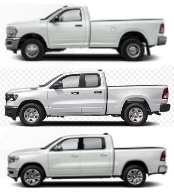

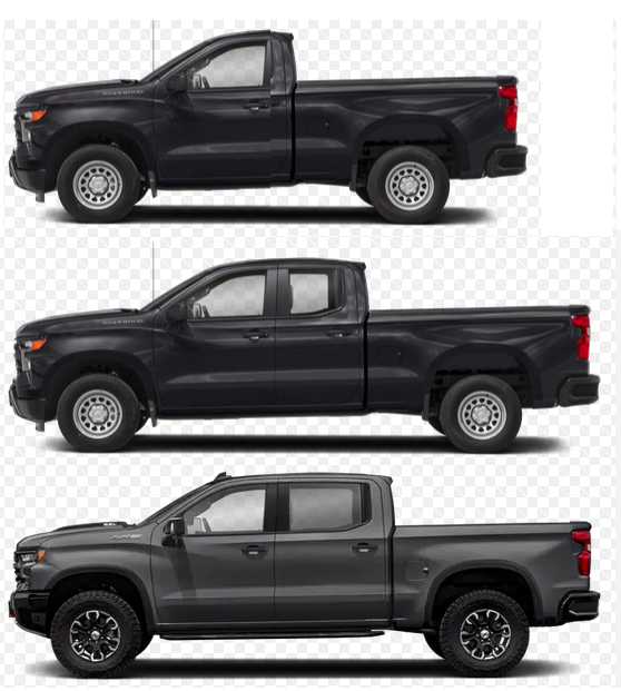 Depicted here are the makes and models of North American built Trucks. For those whom wish to buy new a word of advice. If you buy new a gas or diesel model in the next 6 years, know that your trade-in value in 2030 (when all new vehicles must be electric) will be half of what it used to be and you will likely still owe payments on your purchase. For the rest of us that buy used or are hanging onto our truck we will face a large value drop in 2035 (when even used cars must be electric). We need conversion shops to turn our trucks into electric. Note there are millions of similar relics in automotive junkyards, farmers fields, lining the side of roads, parked in driveways, or garages and even still in use on the streets.
Under the governments plan, New vehicles must be EV only by 2030, Used vehicles sold must be EV only by 2035, and all ICE vehicles must be off the road by 2040. We are talking of replacing 24 million current vehicles with electric by 2040. That is 16 short years. The auto makers know the writing is on the wall and are stepping up with new EV offerings. The ICE (internal combustion engine) reign is over.
The move to Green technology by 2040 is a good thing and will see the following changes:
- 24 million cars, trucks, Vans, suv's will become obsolete and replaced by 2040
- ICE Trade-in values drop 50% by 2030
- ICE Trade-in values drop 75% by 2035
- ICE Trade-in values drop to 0 by 2040.
- Quads, snow mobiles, motorbikes, atv's, collector cars will become unuseable
- Class A, B, C motor coaches will be affected as well
- RV travel trailers, 5th wheels, pop-up trailers will need stronger EV vehicles to pull them
- Not everyone can afford to replace their automobile
- Demand for motors, Inverters, Battery packs will increase
- Charging stations will be needed
- 500,000 tonnes of engines, 250,000 tonnes of transmissions will have to be dismantled and melted down
- Job losses in petrochemical, gas stations, Engine Mechanics, and others.
- Gas stations will be gone
- Petrochemical industry will be trimmed back to natural gas, propane, oils for lubricants
- Roadside service will need portable propane generators to help travelers reach a charge point.
- Wreckers and auto-re-cycler businesses will be overwhelmed with cars with no market for the parts
- Lead acid battery makers and re-builders will have loss of market
- Electric grid demand goes up by 200 Million KW per week for Canada.
Some may think it won’t happen hedging on hopes the government will change. Some will refuse to go EV due to reports of poor EV performance until it is too late, and some will protest the changes and the poor trade-in values on their vehicles.
 Some local governments have been trying to scare people into petitioning for the change not to happen siting that we can’t support the demand on the power grid, loss of petroleum revenue and petroleum jobs. But they are just human form of an ostrich that figures if they can’t see the preditor the preditor (Earth fighting back) can’t see them.
To address these concerns:
- What if we can convert ICE vehicle to EV instead of scrapping them.
- ICE Trade-in values don’t drop if vehicle can be converted to EV by 2040
- ICE Trade-in values drop 75% by 2035 if the vehicle can’t be converted
- ICE Trade-in values drop to 0 by 2040 if the vehicle can’t be converted.
- Quads, snow mobiles, motorbikes, atv's, collector cars will have to be converted to EV or placed in museums.
- Class A, B, C motor coaches will need to be converted to EV
- RV travel trailers, 5th wheels, pop-up trailers will need stronger EV vehicles to pull them
- Not everyone can afford to replace their automobile
a) Tax free EV savings account
b) Grants or low interest loans to low income workers
c) Trade your ride for converted to EV ride
d) Convert your ride to EV
- Demand for motors, Inverters, Battery packs will increase
a) Conversion centers can source motors, inverters, battery packs and driveline adapters from thousands of wrecked EV in scrapyards.
b) New industry to rebuild battery packs into Gcells for EV
c) New industry make driveline parts for conversions.
d) New industry make solar panels for new converted vehicles.
- Charging stations will be repurposed gas stations.
- 500,000 tonnes of engines, 250,000 tonnes of transmissions will have to be dismantled and melted down to make new sources of metal.
- Job losses in affected industries will be needed by new industries.
- Gas stations will be repurposed as charge stations.
- Sorry but these greedy industries have been milking every last cent out of people, businesses and governments for at least 120 years.
- Roadside service will need portable propane generators to help travelers reach a charge point.
- Wreckers and auto-re-cycler businesses will be less overwhelmed if vehicles are converted instead of scrapped. Converted vehicles will still need parts so market for the parts remain.
- Lead acid battery makers and re-builders will have new market by making Gcells for EV. Owners can replace worn Gcells just like they do lead acid batteries. Auto makers will need to change from 1 giant pack to 2 smaller packs called banks with each bank being made from user replaceable Gcells.
Gcells can be re-built.
- With solar electric converted vehicles grid demand could be marginally increase by 50,000,000KW per week in summer and 150,000,000Kw in winter
If we do solar-electric conversions most users will not have need for grid power in sunny weather.
With a potential of 24 million vehicles to convert in 16 years that is 1,500,000 a year, 125,000 per month, and 6250 per day so even if we have 26 conversion sites (2 per province/territory) that is 240 vehicles per day to be
- - inspected,
- - rejected and returned to customer
- - remove ICE parts & scrapped as unsuitable
- - remove ICE parts & modified for
motor/inverter/dashboard/battery/solar additions
To me this a great business model, guaranteed work for
inspectors, mechanics, welders, detailers at conversion facilities for 16 years. Partnered with wrecking yards, Solar cell makers, Motor/Inverter makers, Battery makers, and battery reclaimers,
Now imagine taking a car, van, truck that has served you well, and removing that Internal combustion engine and all that goes with it. Replace it with just 3 to 4 pieces that breathe new life into it. No more pollution generation, life span from a mere 5 to 10 years to over 100 years. All the latest luxuries at a fraction of the cost of going new. But in reality it will be better than new. Not a totally fresh idea. We did it back in the 1970's when Electrohome came out with "BTN". "Bring us your old large console cabinet TV with it's aging vacuum tube chassis and we will put a nice new solid state Chassis in it so you can keep your luxury furniture with new life.". So for the truck we remove the Engine, Transmission, Exhaust, Gas & Tank, Catalytic converter, Muffler, Starter, Lead-Acid Batteries, and old style dashboard. We put in an Electric Motor with Power Inverter, Lithium Ion Phosphate Batteries, Charge controller, Solar array on the roof, and nice new Digital Dash with built in Navigation, hands free phone, Radio with mplayer, Back-up and Dash cams.
With the Universal EV control system in the following pages, it is hoped that any vehicle of any type can be converted into an electric vehicle. In 16 years we face the prospect of over 24 million vehicles of the ICE (Internal combustion engine) type becoming obsolete. In reallity the 24 million figure is expected to increase by 3% each year. Throughout these pages I will outline in detail what the problems we face and how to deal with them.
Chapter 1 Choices
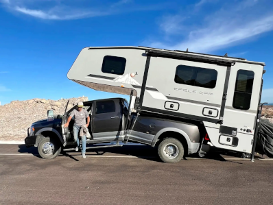 People make mistakes even with their love of the gas hogs like in this real example. The frame cracked in two because the owner used curb weight limits on a regular cab truck when he should have used GCWR on his crew-cab model. This a common mistake because auto-makers list vehicles by curb weight and claim IMHO an exaggerated figure on how
much can be carried or towed. This leads to people thinking that if the vehicle can tow 14000 lbs an 8000 lb camper is ok.
People make mistakes even with their love of the gas hogs like in this real example. The frame cracked in two because the owner used curb weight limits on a regular cab truck when he should have used GCWR on his crew-cab model. This a common mistake because auto-makers list vehicles by curb weight and claim IMHO an exaggerated figure on how
much can be carried or towed. This leads to people thinking that if the vehicle can tow 14000 lbs an 8000 lb camper is ok.
I will be presenting real figures so you the reader can make educated decisions on converting your ride to an EV. Some of the choices to be made are: Purpose (commuter, light work, recreational, heavy work), Range (60km,180km,320km,600km), and more…
In this issue, I focus on North American models although if you can find correct information on foreign model like Toyota, Nisan, Volvo, and many others, they too might be possible. In the conversion of trucks, most are 2wd with the motor mounted back at the rear differential. An inline gear box matches the motor to the differential. The engine compartment can be changed into a storage
bay. For trucks with 4wd, the motor is mounted up front replacing the engine and couples to a modified transmission. The transmission in this case will have just a single gear for both forward and reverse. On 4wd there wouldn’t be storage or much of it up front. Replaceable Gcell batteries of 42A, 84A, or 144A will be fit under
the truck and between the frame rails. The entire pack has 2 switchable battery banks with 8 replaceable Gcells per bank. While you drive on one bank the other may be solar charged and while parked both can be solar charged. Gcells are quite manageable at 34 lbs, 68 lbs, and 116 lbs. Sizes are 10”x10”x6”, 10”x10”x12”, and 10”x30”x6” which are comparable to the old lead acid types.
Not everyone is the same:
Businesses need vehicles with capacity and range to fit their needs. Some place the oness on owner / operators like couriers, taxi drivers, food and prescription delivery, and transports. Others shoulder the burden with vehicles of their own.
Many people are in hard times and saddled with loans on their current ride. A ride that in 6 years will be worth 50% or less of what they paid for it. In 11 years won't be worth anything.
Others also in hard times are fighting to make ends meet while nursing their fully paid for ride. A ride that eventually must be replaced and when that time comes may be worth nothing.
New entrants to the market are at the mercy of credit bureaus and lending institutions. In many cases the option is to buy an old junker for cash or go through a loan shark paying outrageous interest.
Going electric
Has become just as mind boggling as keeping a roof over your head. I hope to shed light on the topic to help.
The pages that follow address these
choices.
Chapter 2 The Grand Plan
My grand plan began as a plan to convert my motorhome to an EV-Motorhome, augment this with a Solar-Electric tricycle for short commutes, and obtain a vehicle to convert into a Solar-electric vehicle. The intent was to fully document these ventures for others who may wish the same course of action.
Then suddenly came NEWS of the Canadian Government's climate actions plans. I was doing my part to honor my mother's wish that I make my Motorhome into an EV and pass on my knowledge. It's no longer about me, I am part of a bigger picture. A picture that will see all of North America being net zero by 2050.
Net zero by 2050 means all forms of power, heating, transportation will be from renewable resources and devoid of carbon production. Canada was one member of 150 countries back 1958 that promised to end coal production and use by 2000, end use of climate damaging carbon emissions by factories, transportation sector, homes by 2030 and in so doing save our planet.
On a federal level, the government is offering people whom wish to save money on their home operations incentives such as rebates on :
- Change out hot water tanks (on gas) to electric instant hot water
- Cover the cost of Solar panels for their homes in 10 select regeons if they cover the installation costs
- Carbon levy rebates to low income households
- Installation of heat pumps
Locally we had a local government that wanted to honor Canada's agreement to the world and end coal by 2030, put more resources into green energy and stop subsidizing petrochemical but the people voted them out in favor of a government that promised to increase coal production and use, give more money to rich oil barons, and ask the people to petition for an end to go green and save the planet.
The auto-makers know that EV vehicles will replace the ICE by 2040. Both USA and Canadian governments have made this clear. Even the EU & China have moved this way already. Political opposition parties have always been a thorn to progress that is why virtually nothing has been done for 66 years. Heck it only took 69 years from the first airplane to putting a man on the moon. I am a problem solver at heart, instead of saying it can't be done, let's say let's find the way to get it done.
We have 16 years and the clock is ticking, 24 million vehicles need to be converted in Canada and 440 Million in the USA. The alternative is that 464 million vehicles become junkyard trash with no market for them. The count goes up on average by 3% per year! The auto-makers are in their glory right now, they see that they have 500,000,000 potential sales in the next 16 years with no regard to the same number of trashed vehicles worth nothing.
To address these concerns: (red=bad green = hoped)
- Federal Government:
- 24 million owners must replace their vehicles
- 24 Million vehicles become scrap which is environmentally disastrous
- National power grid demand up by 200 million KW per week
- Tax free savings plan for EV conversion or purchase
- Grants or low interest loans for low income people to convert their ride, exchange their ride, or purchase EV
- Vehicle Conversion Regulations (inspection, modification, etc.)
- New vehicle Battery standards
- Provincial Government:
- Stop subsidizing petrochemical
- Stop fighting against the federal government
- Stop coal production and use
- Put more effert into green technology
- Offer incentives to atract new EV busineses to locate locally
- Municipal Government:
- find a way to get involved
- Lending Institutions and banks:
- Tax free savings plan for EV conversion or purchase
- Be more supportive of green technology
- Businesses:
- Gas stations will have deminishing sales and must become charge stations.
- Lead acid battery makers and re-builders will have new market by making Gcells for EV. Owners can replace worn Gcells just like they do lead acid batteries.
- Auto sales lots will have to change
Currently they give higher trade in value to ICE vehicles and not much for EV because they don't understand a simple motor that makes no noise and a engine that is noisy, polluting, with 1000's of parts. As ICE is phased out vehicle value on ICE will drop to 0 trade-in with-in 11 years.
- Insurance providers have to change
This business of righting off EV vehicles just because they use battery instead of gas or diesel has to change. They right off 30,000 to 80,000 dolars of battery because no industry is established to check or repair them.
- New Battery Builders / rebuilders business
will need staff to make Gcells
- New Solar panel Businesses focused on Vehicles
will need staff to make custom panels
- Auto makers will need to change from 1 giant pack to 2 smaller packs called banks with each bank being made from user replaceable Gcells.
- Auto Recycle and wrecking yards
You current have the remnants of 60 or more years of wrecked automobiles which you break down into parts for resale and scrap the rest as metal and plastic waste. Over the next 16 years the market for your parts will become zero and all those wrecked and stacked EV's will just keep increasing.
You need to partner with battery rebuilders,
You need to partner with Conversion shops that need you motors inverters and charge ports.
Businesses will be less overwhelmed if vehicles are converted instead of scrapped. Converted vehicles will still need parts so market for the parts remain.
- New conversion shops will be needed
24 Million vehicles to be inspected (inspectors needed)
Auto mechanics will be needed to remove ICE parts for recycle
Wrecked EV can source motors, inverters, battery packs, etc for conversion.
- Some one needs to take my crude designs of Universal dash controler, Battery technology, and solar plans and build our better future.
- General Public:
- Low income owners need way to save for EV
- Quads, snow mobiles, motorbikes, atv's that you wish keep will need conversion too
- Class A, B, C motor coaches will need to be converted to EV
Now in this documentation I will outline how any
truck can also be solar-electric.
Armed with these plans people will benefit from choices to meet their needs when we go green by 2040.
Chapter 03 Travel for free with an EV Truck
It's
high time to move away from the ICE (internal combustion engine) and all that goes along with it. No Engine tune-ups, No Oil changes, No belts to break, No fuel going bad, No spark plugs, No injectors, No power robbing EGR, ECS, Catalytic converter. No archaic FICM, ICS and above all no pollution or hydrocarbon emissions. Just a nice simple
motor and inverter designed to last 1 million miles. Yes you will still have tires that wear, Hubs to repack, Steering parts to maintain, Brakes to redo but the brakes may last 500,000 miles instead of 20,000 miles.
Unlike the auto-makers who are in business to sell new models designed to require a lot of ongoing maintenance, I am going down this path to help vehicle owners keep
money in their pockets, help the planet by NOT creating more waste and pollution. As an EV owner of a converted ICE vehicle you are really exchanging $0.17/mile in fuel (based upon 30mpg @ $5/gal) for battery power $0.08/mile if you recharge at home using 120v AC outlet (based upon 8000 lb vehicle 50KW battery $0.17 /KW ). Yes you have 16
Gcells making your battery pack but instead of having to replace a whole pack every 10 to 15 years like what auto-makers want, you can locate the Gcells that aren’t performing well and replace the ones that are weak far cheaper. With solar recharge you can cut cost per mile to under $0.03/mile. You have control over your costs. If you travel the average of 12,000 miles a year, fuel would cost $0.17 x 12,000 = $2040 and as electric you could spend only $0.03 x 12,000 = $360. In 10 years you have $16,800 + interest and by 15 years $25,200 + interest to cover the Gcells. Battery prices are steadily decreasing in price. What costs $16,000 today is expected to be $5,000 in 5 years!
My Mom summed it up right when she said "this is the final straw. You know electronics, you know computers, you have made so many things so you are mechanical, SO WHY
HAVE WE STILL NOT GOT AN ELECTRIC VEHICLE."
Table 1 Vehicle Classes
 The auto Industry uses curb weight to classify vehicles. They do this because using an average for all models in the class makes sense. The auto-makers do this also to skew the figures for their various models. If they have model ‘A’ with actual curb weight of 3512 lbs and model ‘B’ is 3545 lbs, there isn’t much difference 33 lbs. Model ‘A’ may have a GVWR of 4600 lbs so it can have 1088 lbs of people and cargo but model ‘B’ has a GVWR of 4200 lbs. Model ‘B’ is 33 lbs heavier in curb weight but can only have 655 lbs of people and cargo. The GVWR always identifies the maximum load the structure can support. If you tow or plan to tow a trailer GCWR replaces GVWR because that figure has the maximum structure capability of both the vehicle and trailer. If both models ‘A’ and ‘B’ have a GCWR of 9000 lbs then vehicle model ‘A’ can pull a trailer with contents to a maximum of 9000-4600=4500lbs. Model ‘B’ has a maximum trailer and content weight of 9000-4200=4800lbs. But, and there is always a but, the final restriction on using a trailer is the hitch weight ratio. If the towed trailer has a hitch weight of 900 lbs and the vehicle’s hitch weight maximum is 1000 lbs you are good to go but if the vehicle’s
hitch weight is 500 lbs then you can’t pull that trailer. Some times, the GCWR has two limits 7000/9000 to tell you that a towed trailer without brakes would be 2500 lbs on vehicle ‘A’ and the full 4500 lbs if it has brakes. This is because as you pull a trailer it stretches and compresses the frame during acceleration and braking. THIS ALL PERTAINS TO BOTH ICE AND EV VEHICLES!
The auto Industry uses curb weight to classify vehicles. They do this because using an average for all models in the class makes sense. The auto-makers do this also to skew the figures for their various models. If they have model ‘A’ with actual curb weight of 3512 lbs and model ‘B’ is 3545 lbs, there isn’t much difference 33 lbs. Model ‘A’ may have a GVWR of 4600 lbs so it can have 1088 lbs of people and cargo but model ‘B’ has a GVWR of 4200 lbs. Model ‘B’ is 33 lbs heavier in curb weight but can only have 655 lbs of people and cargo. The GVWR always identifies the maximum load the structure can support. If you tow or plan to tow a trailer GCWR replaces GVWR because that figure has the maximum structure capability of both the vehicle and trailer. If both models ‘A’ and ‘B’ have a GCWR of 9000 lbs then vehicle model ‘A’ can pull a trailer with contents to a maximum of 9000-4600=4500lbs. Model ‘B’ has a maximum trailer and content weight of 9000-4200=4800lbs. But, and there is always a but, the final restriction on using a trailer is the hitch weight ratio. If the towed trailer has a hitch weight of 900 lbs and the vehicle’s hitch weight maximum is 1000 lbs you are good to go but if the vehicle’s
hitch weight is 500 lbs then you can’t pull that trailer. Some times, the GCWR has two limits 7000/9000 to tell you that a towed trailer without brakes would be 2500 lbs on vehicle ‘A’ and the full 4500 lbs if it has brakes. This is because as you pull a trailer it stretches and compresses the frame during acceleration and braking. THIS ALL PERTAINS TO BOTH ICE AND EV VEHICLES!
To deal
with converting an ICE into an EV we can use the curb weight to calculate how much weight we are removing by deleting the ICE stuff (engine, Transmission, catalytic, muffler, exhaust, gas, gas tank, engine support systems) and how much we are adding back with (motor, inverter, charge port, solar array). With luck there is enough left
to put the battery pack. See below…
Table 2 Vehicle Conversion
Vehicle class
|
Curb
Weight
|
ICE
removed
|
EV
added
|
Batteries
|
Net
change
|
|
|
Compact
|
2919
|
-574.20
|
169
|
537.6
|
3051.4
|
-132.40
|
|
Midsize
car
|
3361
|
-691.20
|
198
|
537.6
|
3405.4
|
-44.40
|
|
Large
car
|
3882
|
-782.80
|
227
|
537.6
|
3863.8
|
18.20
|
|
Compact
truck
|
3590
|
-743.60
|
189
|
537.6
|
3573
|
17.00
|
|
Midsize
truck
|
4404
|
-884.20
|
218
|
1075.6
|
5479.6
|
-410.60
|
|
Large
truck
|
5603
|
-1013.00
|
247
|
1075.2
|
5912.2
|
-309.20
|
|
Class
C
|
14000
|
-1194.00
|
334
|
1075.2
|
14215.2
|
-215.20
|
|
Class
A
|
18000
|
-2699.00
|
711
|
1843.2
|
17855.2
|
144.80
|
There are 3 sizes of Gcells 42A, 84A, and 144A. The weight of the battery Pack is 537.6 lbs, 1075.2 lbs and 1843.2lbs respectively. Each Pack has 16 Gcells that are individually replaceable so as to keep costs down for the user. These are average figures based upon vehicle class.
Table 3 Vehicle GVWR
Vehicle class
|
GVWR
|
PAYLOAD
|
TRAILER
|
GCWR
|
|
Compact |
4000
|
1081
|
2498
|
6498
|
|
Midsize
car
|
4565
|
1204
|
3434
|
7999
|
|
Large
car
|
5177
|
1295
|
4692
|
9869
|
|
Compact
truck
|
5763
|
2173
|
3997
|
8760
|
|
Midsize
truck
|
7576
|
3172
|
8924
|
14500
|
|
Large
truck
|
9724
|
5121
|
14000
|
20724
|
|
Class
C
|
14000
|
INCL
|
5000
|
19000
|
|
Class
A
|
18000
|
INCL
|
6000
|
24500
|
In the above, The average GVWR of a class = curb weight + payload. Trucks include SUV type vehicles. The compact truck includes mini-vans, smaller suv’s, and small trucks like the ford Currier. The Midsize truck includes regular cab, extended cab, and crew cab of half ton pick-ups and even some ¾ ton pick-ups. Large truck includes ¾ ton and larger types With the GVWR and GCWR we can approximate range of travel with and without a trailer. If the pack weight is 1075.6 lbs it has 84A Gcells in two banks per pack so pack amps is 168A. All Packs are 384v so our
Kwatts = (V *A)/1000 = (384*168)/1000 = 64.512KW. Now take the GVWR/10000 to calculate KW/mile so if we take a midsize truck 7576/10000 = 0.758 kw per mile and using KW/0.758 = 85.11 miles to a charge. Pulling a trailer KW/1.45 = 44.49 miles. This isn’t too impressive but that is fully loaded to the max. Same truck but only carrying the driver at 200 lbs is 64.512/0.448 = 144 miles. The average person drives 12000 miles a year according to the insurance bureau of Canada so you get 4.5 days per charge. Solar charging can replenish up to 0.9kw of the 8kw used while you worked or visited. You get home and plug in and are fully recharged 7 hours. Gas would have cost you $5 and electricity cost you $2.38. A month of commuting to work using gas $100 and using electricity raised your electric
bill $47.60.
If you bank the $2.62 that you would have spent on gas + oil changes you will have the money to replace the batteries that may fail. Keep in mind that battery cells making up a pack degrade at different rates. The prius, focus, and every other EV currently available use one huge pack. When a cell degrades the whole pack is replaced and they just scrap the pack. Did you know that when a Tesla pack that was end of life was taken apart and the cells tested, less than 4% could have been replaced to return the pack to ~100%. We use Gcells which are individually replaceable and can be rebuilt. So if one Gcell is giving trouble you only need replace it. In fact a properly equipped battery shop could take the Gcell apart and replace the worn cells. You see as batteries age they take less charge. Charging stops when the weakest battery says it is charged.
So you have your EV and 9 years in to using it you notice you used to get 144 miles to a charge and now get 100 miles. 40 miles on bank 1 and 60 miles on bank 2. Load testing the Gcells you see 2 in bank 1 and 1 in bank 2 are far weaker than the rest. So you replace them and find now you get 136 miles from the pack. If you had of continued without changing out weak Gcells by year 12 you might be down to only 40 miles to a charge or less. Point is that if cost of the whole pack is $32,000 and 3 of 16 were weak you got almost full range back for $6000 instead of $32,000. You may even be able to do a kind of pack tune-up. Move all the strongest Gcells into I bank and replace the weakest ones to make the second bank good.
Another angle is for the people with short funds availability, they can begin doing one bank of batteries and have a short range of use (full pack is 2 banks $16800 with range of 144 miles, 1 bank is $8400 with range of
72 miles). When you can afford the additional bank you add it for full range.
In table 2 above you may have noticed the ‘net change’ value was higher than the curb weight in some cases. This is due to compensating for battery weight by in effect reducing payload weight listed in table 3. We aren’t looking to modify the overall GVWR because that value defines the structural limits of the frame.
Table 4
Vehicle Range
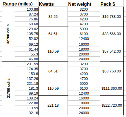 Because my focus is on affordability not only to convert but also to maintain, the choice was made to build Gcells from 32700 type cells. While they are larger and heavier than 21700 type cells they are less expensive.
Using the Gcell concept you can make 1 bank of the pack ~$8400 for 42A Gcells and run with half range. Add the second bank later for full range. A full pack weighs 544 lbs for $16,788 and a 42A pack using 21700 cells is 188lbs for $26,000. At the left I show we can double the range by upgrading to 84A Gcells and because they are lighter but way more expensive.
100Miles = 166kms
As you see the heavier your net weight (curb weight + batteries + people + cargo), the shorter your maximum range becomes. I have included both 32700 type Gcells and 21700 type Gcells. In the listing. There is really no point in using 40A 21700 cells @ $26,000 to achieve the same range as using 42A 32700 Gcells for $16,788 so instead I up the first category to be 80A 21700 Gcells but you get double the range for 3 times the initial cost. All Gcells in a bank must be the same amperage. In general you can have bank 1 and bank 2 both the same or can have bank 1 and bank 2 at different Ah. If bank 1 & 2 ar 42A then Pack is 84A. If bank 1 is 84A and bank 2 is 42A the pack is 126A. You technically if space and weight limits permit, even wire a bank in parallel such that bank 1 has 84A Gcells, bank2 has 2 banks attached in parallel of 84A+42A. Under such a situation when on bank 1 your range = 126 miles but on bank 2 you get 190 miles. During charge cycles the charge times would be appropriately longer.
So here comes another wrinkle. You generally commute to and from work and other activities using your car or truck with no issue but long trips or going on vacation with your trailer you just can’t make it. A piggyback port might be the answer. With a piggyback port an external battery pack loaded into your trunk, truck-box, or in your trailer might just give the edge. Yes you are reducing payload weight by the weight of the pack so it is a judgment call.
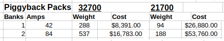 32700 Gcells are 10”x10”x6” and 34 lbs ea. and 21700 Gcells are 6”x6”x6” and 10 lbs ea. So a single bank can be made as small as 10”x40”x12” or 12”x24”x6” bsed upon type of Gcell.
You would only carry the Piggyback bank or pack when you need the extra range. So your truck gets 144 miles from it’s 168A pack with one occupant but now you are going 180 miles (300km) with the family to visit Edmonton from Calgary. Your payload just increased by 400 lbs. The piggyback bank is added to your truck box and now you have 210A Pack. You now have 80.4KW and 0.448 + 0.06 = 0.508kw/m so your range is now 159 miles (264.5km). Okay so my example may need a stopover in Red deer to recharge because we are still 31 miles short. But we did manage to extend the range with added payload weight (family). If it was just you going on the trip you could just make it there with the piggyback bank. It wasn’t that long ago that gas and diesel vehicles had such short ranges that people carried jerry cans of fuel so they could make a trip. In time engine performance was improved, new lighter frames and bodies improved range.
Adding a Piggyback Bank or Pack to a trailer can also be of benefit. Lets take the family on vacation with the trailer to camp. Our truck GVWR = 7500 lbs of this we are using 5080 lbs (family+in truck bed piggyback 42A). We attach trailer (5000 lbs loaded) + another piggyback (84A 578 lbs). GCWR = 14500 lbs and we are using 5080 + 5578 = 10,658 lbs. Our kw/mile = 1.065kw/mile. Our total pack amps has increased from 168A to 294A. Our pack KW has increased from 64KW to 112.89KW so our range is 112.9/1.065 = 106 miles (176km) with family, supplies, and camper. Recharge at campsite for trip home.
Should you suffer a Battery cell dying, your unit will not be stranded without power, as the other bank will provide limited power till you can fix the issue.
1. Why would you do this Well, frankly for a number of reasons. YMMV. In my journey to being a full time RV er, I don't travel much; but when I do, cost of fuel for distance traveled is an issue. Here is my go to list of reasons to convert:
• Fuel Tank size : 80gal(288 Ltr) at $4.68/gal(1.20/Ltr) = $374.40/Tank ** Cost per mile $1.28 if all goes well
• Distance/Tank : 480miles (800km)
• Electric charge: 200A * 120v = 24000watts / 1000 = 24kwh * $0.15 = $3.60 /116km ** Cost per mile cut to $0.05 WOW factor
• More environmentally friendly (no harmful carbon emissions)
• No oil changes
• No Mechanics
• No tows
• Having an older fully paid for vehicle converted for hopefully about $37800 which is by far, 50% cheaper than a new gas hog.
• Over the lifespan (15yrs) of a typical gas hog
◦ Unit cost $30,000
◦ Usage costs :
▪ @20000km/yr $3500 Maintenance of $3450. YMMV.
It's only $84,650 over 15 years
▪ In the end you get to replace your unit and do it all again.
• But EV has a better approach.
▪Same $30,000 vehicle,
▪charging costs of 0 to $540 per year,
▪conversion costs $37800 grand total of $74,900
▪In the end of 15yrs you can replace the batteries from the money you saved not buying fuel or doing oil changes and engine repairs.
• Most drive trains are rated for 350,000 miles mainly due to engine and associated systems. Take that ICE (internal combustion engine) and all that goes with it out of the equation and replace that with an EV motor, controller, inverter, batteries rated for over a million miles and your now talking progress.
2. Why you should not do this:
• Local gas stations won't like you.
• Gas companies also won't like you.
• The municipalities may worry about what your unit will place on it's power system. (few understand that 30A 120v AC can not deliver more than that).
• Costs are prohibitive.
• You like paying high repair costs
• You have more money than you need anyway.
• Car dealerships won't be your friend either:
◦ they want to move new models not have people choose to stay with the same old model.
◦ As long as you are running on gas or diesel they know how to talk the talk and convince you into the nice new unit and know how to resell your unit.
◦ If it's an EV how do they talk you into a new unit and how do they rate your old unit to resell it.
• You'll here claims that you are hurting the economy and putting people out of work because you aren't choosing to be broke. awh!
3. What's the first thing you need to consider? Weight :
• You are removing 28lbs of gas tank plus 260lbs of fuel if full,
• about 675 lbs of motor,
• 40lbs of exhaust
• for about 1000 lbs.
• Then you are adding 120 lbs of electric motor,
• Inverter and controller for about another 20 lbs.
Hmm, not bad saving 860 lbs. But, and there is always a but, you need batteries and a lot of them. Lithium ion cells configured into 384v banks @ 82Ah weigh 544 lbs compared to 32x 12v lead-acid batteries of
85Ah at 2720 lbs that's why electric cars use them.
5 yrs ago the cost to do one these conversions spiked at about $80,000. Today it runs starting about $16,800 and in five years is expected to be about $5,000 or less.
Where do you put all those
batteries?!!
How much will they weigh?!!
Can my unit handle the weight?!!
Are all good and necessary questions.
To address these lets look at where to put them.
- In car conversion, limitations of weight and space means that in order to handle the batteries you
must give up space, under the rear seat, in the trunk, under the engine compartment hood. And due to weight limits you may not have enough to go very far on a charge.
- Trucks (pick-ups, tractor trailer units) can handle more weight but still may not be enough space for the batteries.
- Buses and other large frame units, have the clear advantage. The frames can handle the weight, space under the frame and where the engine used to be is ample space.
Beyond
just Motor, Inverter, Controller and Batteries
There are things to note about the differences between an ICE (internal combustion Engine) and an EV (Electric Vehicle):
Are the Brakes Manual, Hydraulic, Boosted hydraulic, Vacuum, Electric, Air?
Hope you planned to keep the radiator because you will need to cool the Inverter and motor.
Will your windshield washers work?
What about window defroster, cabin heat?
Emergency contingencies
Licensing, Insurance and regulations?
Brakes:
The Boosted Hydraulic tend to use a
vacuum from the ICE motor to assist in braking. You have just
discarded the motor so need to find an electric replacement for the
vacuum supply
Cooling:
The motor under load gets hotter the faster you travel. Believe me
you have a lot of load at 1 to 2 tonnes. The Inverter too goes
through a lot of load pains as it calls for more power. The original
radiator, with a fan and appropriate water pump will need to
circulate water through or around both the motor and Inverter
Wash and Wipe:
To my knowledge all vehicles use an electric pump run on demand.
Likewise the wipers are already electric. So for our conversion all
we need is to provide 12v battery power for these systems. That same
battery power can run the radiator fan and water circulation system.
That means we need to tap 12v from the 48v battery packs.
Defrost and Heat:
While rear window defroster is electric so we are ok at the back.
We might be able to tap into the cooling line for the motor and
Inverter and use a set of salvaged electric ceramic space heaters to
create a means of both defrosting the windows and providing cabin
heat.
In an Emergency:
Because EV battery packs are carefully monitored during charge or discharge you won’t have to worry about this.
For our lowly EV there are just too many misconceptions usually brought on those feeling threatened like auto salespersons, mechanics, people reacting to news and drawing wrong conclusions.
There are hundreds of reports about cell phone batteries and computer batteries
catching fire and being so dangerous because they are lithium. This is true but, and there is always a but, There are hundreds of types of lithium battery. The kinds used in cell phones are rapid charge without either of ecm (electric charge maintenance) or also known as
BCM (Battery charge monitoring) and cooling. The kind used in EV must be managed by a charge system with BMS and are of a more stable form of Battery than a cell phone can have. Temperature is regulated both during charge and normal discharge.
In any accident vehicles have what is known as an inertia switch intended to cut power to the unit and diesel or propane vehicles have a master fuel shutoff as well. For those looking to convert a vehicle
to EV, the powers that be have made the following ruling, "An EV of any type must have an inertia switch that immediately cuts power to the motor in the event of a collision. There must also be a master Battery cutoff with clear notification where it is and how to access the batteries for safe disconnection".
In my design, an Inertia switch kills the power to the batteries until reset. A master shutoff is located inside the driver seat area, with notices inside and out where it is. And each bank of Batteries will have a Bank shutoff. I tend to enclose the Banks such that no-one including me
can have access to the dangerously high voltages and currents of the battery banks.
The laws:
The legalities are changing daily it seems. As more people turn to evehicles, the provinces and states are re-writing the books. As of this writing I learned that all that required in Alberta is to register the vehicle as an evehicle. It licenses just in the normal sense. No change to drivers licensing rules. The insurance industry is a little behind the times. True they
need to know that the evehicle conversion is done right and posses no threat to people property or roadways. For this they ask you to provide a proof of compliance from a vehicle inspection outlet.
At the inspection outlet you can expect them to check things like what have you
modified in the structure of the frame, axles, brakes, Emergency Brake, and how have you mounted and secured the motor. Have the battery packs been built to tight transportation safety standards. If you don't pass, expect big problems in the future. As stated above you must provide an Emergency shutoff with clear notices as to how to disconnect Batteries. And you must have an inertia switch. These things inspectors can fail you on.
When I first started considering my earlier motorhome project:
I came armed with over 40 years of Electronics experience, Computer science experience, Computer programming experience and some Power electrical experience. Still I listened to those from many walks of life and perspectives for insight on things I
may not have thought of. We are now at the point where the gearheads fought hard to discourage me from going down this path. It's plane Idiocracy. You know if there is something in my long life I have learned is that it is filled with people who can't or just won't think out of the box. I am
going to quote lyrics from a Harry Chapin song here that fits the bill of my point.
The little boy went first day of school, He got some crayons and started to draw
He put colors all over the paper, For colors was what he
saw
And the teacher said.. What you doin' young man
I'm paintin' flowers he said
She said, It's not the time for art young man
And anyway flowers are green and red
There's a time for everything young man, And a way it should be done
You've got to show concern for everyone else, For you're not the only one
And she said: Flowers are red young man, Green leaves are
green
There's no need to see flowers any other way, Than the way
they always have been seen
But the little boy said: There are so many colors in the rainbow
So many colors in the morning sun, So many colors in the flower and I see every one
Well the teacher said
... Well long story short the boy was punished and later in life he was at a new school with happy people who painted flowers in all colors and all the boy could do was gruffly say
Flowers are red, green leaves are green, there is no need to see them any other way than the way they always have been seen.
Here is the point.
- I understand that people who are making their living in the fossil fuel industry don't want to see anything that might take that away.
- Those in product sales like Automotive sales outlets, RV sales outlets don't want a vehicle that lives forever
- Mechanics and automotive parts suppliers also see the drive to go to electric vehicles as a big mistake because that will hurt their livelihood if people don't have vehicles that will break down.
I
don't think I or anybody that I ever associated with wants anybody to
loose their jobs or livelihood. People make up facts or false stories
to discredit EV as the worst idea to ever come along and this just a
sign of short sightedness. The same mechanics that tried to
discourage me from going EV are proud of the fact that they defeated
their EGR or catalytic converter to get better gas mileage or more
power. Or flaunted how they add nitro to their mix to make a mean
racing machine. But I am crazy to find a way that saves money and is
legal.
Should I be apologizing because...
Round trip for my gas hog took $20
fuel before conversion but same distance after conversion will
likely cost $3.60 electricity, and if the commute is a daily thing,
it would cost me $7.67 per day towards eventual battery replacement.
So instead of spending $20 for a daily trip it costs me $11.27 and
over half of that is put in savings.
I no longer need oil changes every
3 months or 5km
My brakes can last over 500,000
miles instead of only 20,000
My motor can go at least a million
miles before I need do anything but the gas hog is going to be
screaming for seals, belts, hoses, plugs, additives, and much more
at least 5 times over that same period
My EV causes a little bit of
carbon emissions during the generation of electricity to charge me
but your gas hog creates enough deadly emissions that if you run it
in an enclosed space you kill everyone in that space from carbon
monoxide poisoning. And also that carbon emission used to charge me
would still be generated for home heating, cooking, etc. even if I
didn't charge an EV.
Yes I got to go home to charge or
find a charge spot elsewhere on my travels and it can take 4 to 13
hours to get charged which is different than your gas hog that can
be filled up almost at any street corner. But a hundred years ago
people who could afford cars had to hope their local station didn't
run out of gas because stations were not that plentiful. It all
takes time.
On a cold rainy day, I can drive home and plug in my EV go in
side and stay dry. But you got a gas hog so you got to stand in the
rain and get wet and cold to serve your master "the gas hog".
On a daily compute of 24 miles round trip operational costs of
$95,000 for a regular gas conveyance is a mere $23,370 over 5 years
because the cost of the electric includes $16,800 of electric
batteries replacement @ $7.67 per day banked towards the need.
It is my hope that after you read the following pages you will too
see the basis for the information I have summarized above.
Chapter 04 An EV Truck: The Chassis
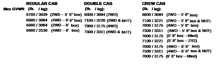
A look at the chassis of trucks. We will be looking at 3 makers and 3 cab styles each.
The Chevy / GMC series
There are 11 types of truck with differing roof space for solar panels and frame dimensions that affect GVWR, payload, and curb weight. Remember the GVWR defines the maximum weight allowed by the
factory that built the truck. If towing is involved GCWR = GVWR + GTWR where the GTWR defines the maximum weight of towed trailer. The trailer will have a GWR that must be less than or equal the GTWR of the truck. The truck and trailer will also have a hitch weight. The hitch weight of the truck must be higher than the hitch load of the trailer.
Cab styles change the curb weight involved so you must use the correct curb weight, GVWR, GCWR for the vehicle you wish to convert.
 A weigh scale can be used to measure weights of engine and
transmission etc. removed from the vehicle and weights of
motor/inverter added to determine what is available for battery Packs, and solar. Solar are 29lbs on average and provide 1 to 2 amps each with 1 to 3 panels per roof type (regular, extended, or crew ) cab. Using the frame layout below we see a lot of variation in frame height above ground level. Dimension G is 10” above ground on all models and is lowest point on the frames. Ignoring the wheel wells
the highest points are F and I being 13 and 17 & ¾ respectively. Using H & I we have about 6” depth to the frame. So G – 3” = 7” true height clearance. Mounting a protective plate to the bottom of the frame at point E and extending back length of R and attaching to the rear frame at that point gives us 6” at the front increasing to 10 ¾” and again increasing to 12 7/8” at the back. R varies from 46” to 129” by model. All this defines space for batteries between the frames. Frame spacing is 28” so at the front
we have 6”x28”x ? ” then ~10”x 28” x ? “ then 12” x 28”
x ? “ at the back. You need to determine the values for the (?) by measurement. If the first (?) is 10” then you have room for 2 Gcells on flat followed by 7 rows of 2 Gcells standing up to 17 rows of 2 Gcells. So the CA105 and KA105 has room for 16 Gcells, the Vans have room for 12 rows of 2 Gcells and most pick-ups have room for 17 rows of 2 Gcells (4 banks or 2 Packs) of room. The pick-ups have room for 2 packs of 84A or 1 pack of 168A or 1 pack of 288A if weight
permits.
A weigh scale can be used to measure weights of engine and
transmission etc. removed from the vehicle and weights of
motor/inverter added to determine what is available for battery Packs, and solar. Solar are 29lbs on average and provide 1 to 2 amps each with 1 to 3 panels per roof type (regular, extended, or crew ) cab. Using the frame layout below we see a lot of variation in frame height above ground level. Dimension G is 10” above ground on all models and is lowest point on the frames. Ignoring the wheel wells
the highest points are F and I being 13 and 17 & ¾ respectively. Using H & I we have about 6” depth to the frame. So G – 3” = 7” true height clearance. Mounting a protective plate to the bottom of the frame at point E and extending back length of R and attaching to the rear frame at that point gives us 6” at the front increasing to 10 ¾” and again increasing to 12 7/8” at the back. R varies from 46” to 129” by model. All this defines space for batteries between the frames. Frame spacing is 28” so at the front
we have 6”x28”x ? ” then ~10”x 28” x ? “ then 12” x 28”
x ? “ at the back. You need to determine the values for the (?) by measurement. If the first (?) is 10” then you have room for 2 Gcells on flat followed by 7 rows of 2 Gcells standing up to 17 rows of 2 Gcells. So the CA105 and KA105 has room for 16 Gcells, the Vans have room for 12 rows of 2 Gcells and most pick-ups have room for 17 rows of 2 Gcells (4 banks or 2 Packs) of room. The pick-ups have room for 2 packs of 84A or 1 pack of 168A or 1 pack of 288A if weight
permits.
Chevy GVWR specs
Model CA314 Double cab GVWR 6800 lbs 2WD selected
for conversion.
Chevy wheelbase & ground clearance
 wheelbase 147.4 in.
ground clearance 7.8 in.
Chevy Payload specs
 5.3L 1920 lb payload
curb weight 4920 lbs
The Dodge RAM series
There are 16 types of truck with differing roof space for solar panels and frame dimensions that affect GVWR, payload, and curb weight. Remember the GVWR defines the maximum weight allowed by the factory that built the truck. If towing is involved GCWR = GVWR + GTWR where the GTWR defines the maximum weight of towed trailer. The
trailer will have a GWR that must be less than or equal the GTWR of the truck. The truck and trailer will also have a hitch weight. The hitch weight of the truck must be higher than the hitch load of the trailer.
Cab styles change the curb weight involved so you must use the correct curb weight, GVWR, GCWR for the vehicle you wish to convert. A weigh scale can be used to measure weights of engine and transmission etc. removed from the vehicle and weights of motor/inverter added to determine what is available for battery Packs, and solar. Solar are 29lbs on average and provide 1 to 2 amps each with 1 to 3 panels per roof type (regular, extended, or crew )
cab. Using the frame layout below we see a lot
 of variations in the frame and they don’t give ground clearance. We are interested the frame spacing from the 3rd cross member to the 5th cross member for this is where we likely can place batteries. The frame seams to be 6” to 7” depth x 2” to 3” width. Frame spacing about 36”
 Dimensions and weights for the Ram 1500, the 2500 and 3500 were not found.
The Ford chassis series
There are 12 types of truck with differing roof space for solar panels and frame dimensions that affect GVWR, payload, and curb weight. Remember the GVWR defines the maximum weight allowed by the factory that built the truck. If towing is involved GCWR = GVWR + GTWR where the GTWR defines the maximum weight of towed trailer. The
trailer will have a GWR that must be less than or equal the GTWR of the truck. The truck and trailer will also have a hitch weight. The hitch weight of the truck must be higher than the hitch load of the trailer.
Cab styles change the curb weight involved so you must use the correct curb weight, GVWR, GCWR for the vehicle you wish to convert. A weigh scale can be used to measure weights of engine and transmission etc. removed from the vehicle and weights of motor/inverter added to determine what is available for battery Packs, and solar. Solar are 29lbs on average and provide 1 to 2 amps each with 1 to 3 panels per roof type (regular, extended, or crew )
cab. Using the frame layout below we see a fairly consistent frame 34” width but the distance from F to C

 mounts is missing where we need the ground clearance value and length. All we know is frame depth is 6” to 7” which can support Gcells on flat and frame width can hold 3 Gcells across so as long as F to C is at least 5 feet we can hold 16 x 42A Gcells, If road clearance is at
least 13” we can do 16 x 84A Gcells in 5 feet and we can do 6 x 144A Gcells. or 12 x 144A if clearance is at least 13”. I can guess with 22” wheels we would be guaranteed 11” clearance.
mounts is missing where we need the ground clearance value and length. All we know is frame depth is 6” to 7” which can support Gcells on flat and frame width can hold 3 Gcells across so as long as F to C is at least 5 feet we can hold 16 x 42A Gcells, If road clearance is at
least 13” we can do 16 x 84A Gcells in 5 feet and we can do 6 x 144A Gcells. or 12 x 144A if clearance is at least 13”. I can guess with 22” wheels we would be guaranteed 11” clearance.
The wheel base values
 The GVWR of the models

Specs for 17” wheels

Specs for 18” wheels
*** There are also another chart with specs for 18” duleys.>
Using what I learned from the motor home conversion, If we have 3 basic Gcell Types all being 48v for easy charging and compactness, we can do any size of vehicle. The smallest Gcell is 42Ah, followed by 84Ah and finally 144Ah. Where a 12v lead-acid battery is 85 lbs, the Lithium ones would be 34 lbs, 68 lbs and 105 lbs respectively. With
12v batteries at about 9”x7”x10” the Gcell▪s are 10”x10”x6”, 10”x10”x12” and 10”x30”x6”. So it is possible to source Gcells at local stores like we do for lead acid cells and old Gcells can be recycled for rebuild just like lead acid are done now.
Chapter 05 EV Truck: Drive Train
Drive train investigation
The end goal is to be able to move a 3400 lb mass on command. This relies upon the motor, gearbox, Inverter, and cooling technologies. We know that work creates heat. So if we expend energy to drive a motor fast,
it will heat up because it is under load. Supplying that energy is an Inverter that changes Battery power measured in DC to alternating power called AC. The inverter therefore also will be working hard.
Ultimately we want to move 2 tonnes (4000lbs) from 0 to 120kph (0 to 72mph) and we would
like to maintain this for 200kms (120miles). The laws of motion do not change just because we are driving the motion by a different method. So the distance traveled by the rotation of a 14" diameter tire will always be 3.14 (pi) x 14 (d) 43.96 inches until the tire wears down to it's minimum diameter of 13.21 inches which means it only travels 41.48 inches.
Mileage does not change either. There is 5280 feet in a mile and 12 inches to a foot. That's 63,360 inches to a mile. From this we can tell how many rotations of the tire are needed to cover the distance. (63,360
/ 43.96)= 1441.31 r/m. The differential uses a ratio of how many turns of the drive shaft it takes per rotation of the tire. We need to know this ratio as it will tell us how fast the gearbox output shaft must spin to make 1 rotation. Multiply that by the number of rotations per mile and we have the first part of the equation.
From the above we now can work out rotations needed to go a specific distance and then work out the maximum time we want to take to make that distance. So if our differential is 5:1 then we know the drive shaft spins 5 times to turn the wheel 1 turn and 5 x 1441.31 = gearbox turns to go 1 mile = 7206.55 r/m. Rotations are counted in rounds per minute (rpm). There are 60 minutes to an hour. So if we want to go 1 mile per hour, we need to divide 7206.55 by 60 minutes
to get the rpm. Which in this case is 120.1 rpm. To do the top speed of 72mph our gearbox will be rotating the driveshaft at 120.1 x 72 = 8647.86 rpm.

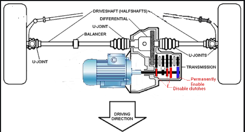 The preceding applies to a rear wheel drive but, and there is always a but, the Car is front wheel drive. It still has a differential but the differential is part of the transmission not connected to the
transmission using a drive shaft. With FWD our CV axles mate with the differential gear inside the transmission. The differential gear mates with an output gear on a secondary shaft. The secondary shaft has 2 to 4 clutch gears. A clutch gear when unpressurized free spins. Force hydraulic pressure into the clutch and the outer gear transfers rotation into the inner gear on the output shaft.
The preceding applies to a rear wheel drive but, and there is always a but, the Car is front wheel drive. It still has a differential but the differential is part of the transmission not connected to the
transmission using a drive shaft. With FWD our CV axles mate with the differential gear inside the transmission. The differential gear mates with an output gear on a secondary shaft. The secondary shaft has 2 to 4 clutch gears. A clutch gear when unpressurized free spins. Force hydraulic pressure into the clutch and the outer gear transfers rotation into the inner gear on the output shaft.
A series of solenoids are used to redirect hydraulic fluid to the appropriate clutch gear. Only 1 clutch engages at a time. All the clutch gear outer gears mate with different size gears on the main shaft. In this manor, when a specific clutch engages, it's outer gear transfers the new ratio to the secondary shaft. The Main shaft mates with a flywheel clutch gear that when presurized transfers rotation
from a torque converter to the main shaft. The torque converter mates with the engine output shaft. Part of the torque converter and Flywheel clutch has a hydraulic fluid pump that is used to pump the hydraulic fluid to the necessary components.
At top speed of 66mph, driveshaft rpm is 2907.5rpm. At local highway speeds here of 100kph to 110kph (60mph to 66mph) we need a motor that can sustain an rpm of 3000. Most motors run 500 to 3500rpm as upper limits with 1500 being a go to standard. This would mean we need a gear ratio of our gearbox to be 6:1 @ 500rpm and 2:1 @ 1500rpm and 1:1 @ 3000rpm. But from the source "electric cars are for girls" they say Most AC electric motors run 230v AC @ 60 Hz and a top speed of 1750rpm. They also say that to create 230V AC from a DC source you need 340V DC from your Battery pack. Not to be thrown some curve, it's time to do more investigation. I tried to find some concrete facts about motors, torque, and weight classes they can safely handle but none could be found. So time for different approach we will review TV programs from "Jay Leno's Garage and web cast from EV west to try and get more info.
Jay Leno's Garage did 2 EV Bus Episodes. One was for Econoliner in California and the other was a repurposed Transit bus. Both busses were about 18000 lbs without passengers and 38000 lbs when full of passengers. In comparison to my first project (an EV Motorhome), My fully loaded motorhome comes in at 17,500 lbs and 24,500 when towing a car behind it. My Motorhome is therefore lighter. The Busses have a kwh/m of 1.8 to 3.8 depending on load, where my Motorhome is 1.75 to 2.4 depending on load, and a Car is 0.34. Both busses use more than 360v @600 Amps = 234Kw and where the repurposed bus provides that it can travel at highway speeds of 50mph for 100 miles to a charge, the Econoliner travels in the city with many start stops at an average speed of 9mph over an 18mile route with fast recharge enroute and runs 24 hours a day. The values for the repurposed bus suggest it is making the trip at far less than full since they have 234kw and to do 100 miles would take 380kw if full of passengers. In the episodes, they mention HP is about 170 to 200 and that the real killer is torque. Because electric motors have instantanious torque it tends to destroy conventional transmissions based upon multiple gear ratios so EV's are better off with fixed gear styles. And lastly that an expected decrease of brake wear of 50% was remarkably exceeded such that brakes should last > 500,000 miles over the ICE at 20,000 miles.
The EV-West podcast basically itemized how a DC electric motor is much larger than an AC motor of the same drive potential. While DC motors are plentiful and cheaper, both in cost of the motor and in cost to control them, they have serious limitations. Firstly, the maximum vehicle weight of 3000 lbs from a single motor and ganging two motors
to increase load capabilities is counter productive. The motor weight itself is heavier than an AC motor. Two DC motors is 1 & 2/3rds heavier than an AC motor and typically 30" long compared to an AC motor that is 15" to 18" long. DC motors run much hotter then their AC counterpart. Heat is so high that long distance at higher speeds is almost impossible without a custom transmission.
Ok so here is what I learned from this:
- DC motors won't work they have to be AC drive
- Weight/10000 = kwh/mile
- Interior amenities are run from regular batteries and recharged by an inverter.
- HP is between 170 and 200, Torque at about 1200 ft-lbs
- 50 mph. is not a problem and with the right gearing 66mph is doable
- With regen braking brakes may last 25 times longer than on ICE
- A small 15" x 20" electric AC motor drives the axles through a gear box connected to the differential. The motor is run by an inverter and controller.
- braking is regenerative
- They may have 1 battery pack for a total of ~360 volts. That means the battery pack need to add up to 360+v and lithium ion cells which they are also using are 3.2v each. That means 1 pack contain a minimum of 113 cells in series. Then they have 230.4 kWh in the spec. v x A = w so 230400 / 384 must equal the A rating. Which is
600A. So this bus is probably using 462 cells in parallel if using
18650 cells for a total of 55,440 cells.
In chapter 12 we will go into depth on the batteries. We will cover types of battery and the effect on quantity, organized grouping, Pack Voltages, Current, Wattage and a number of other factors.
On the bright side it does confirm what"electric cars are for girls"said about AC motors needing over 340v DC to get 230v AC for the motor. Both bus conversions talking about ~360v in Battery power. With high voltage source and stepping it down by 1.669 to get 230v AC, the current demanded by the AC motor is 1.669 less at the source. As a result, An AC motor demanding 10A @ 230v means the source actually only needs supply 5.99A. This is the run current. At start, the first 1/60th of a second (based upon 60Hz) has surge current about 25 times higher for that 1/2 second. So our 10A motor can be expected to draw 250A for 1/2 second then as the rotor of the motor begins to turn the current drops over the next 6.5 seconds to under 60A then in full rotation settles at the 10A. This of course assumes
the motor is being told to run at maximum rotational speed. What happens at the motor is reflected equally at the source. The source will see 150A surge for 1/60th of a second then 6.5 seconds of 36A and then the run current of 6A. This is similar to what happens on an ICE when the starter engages. The ICE Battery has a rating of 800 to 1500 cold cranking amps. As you turn the key to start the battery must supply 800Amps plus thru a 2/0 cable to the starter and 60 to 80 amps to the spark plugs. Once the engine is running, an alternator recharges the battery. If the alternator fails or the belt breaks, the battery supplies the 60 to 80 amps until the 85Ah battery is depleted. Then everything stops.
So moving on...
The Drive Inverter sits up front with the motor so it's three 2 gauge cables can adequately supply the motor. Under the chassis to the back we have a lighter 4 gauge cable to the charge port and batteries. The cables are overkill as far as run current goes. They are specific to handle the surge currents.
Our Truck conversion replaces the 675 lbs engine with a 190 lbs motor & inverter. The rear wheel drive transmission is replaced with a shortened driveshaft and a gearbox The fuel tank is only 25 lbs empty and 207 lbs full. The batteries are going to take 585 lbs at least. Under full occupancy, passengers and cargo are qualified at 1980 lbs to meet the GVWR of 6800 lbs. Again we want solar charging which might add as much as 90 lbs. So our battery needs are 0.68kwh/m.
The cells are a difficult concept because it refers both to a cell being a tiny cylindrical AA type battery and also to the groups of them
forming the whole. A prismatic cell is made from 100's of individual AA type looking batteries also called cells.
Motors
Three types of motor for EV's. We have the old low voltage type DC motor, The newer tech AC 3 phase, and the OEM AC 3 phase. All three can move the Car but each has it's own set of problems.
DC Motor
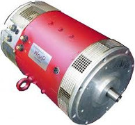 Typically run from 12v lead acid cells, it is abundantly available, low in terms of cost, and great low end torque. At higher speeds, it has virtually no acceleration. It works fine at low speed short distances but can overheat easily under heavy load, higher speeds, or long distances. The controller is simple and regulates the speed only.There is no regenerative braking (free wheels) and needs a transmission to accomplish speed range and reverse features. Heavier motors
AC 3 phase Motor
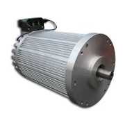 The go to solution for most EV conversions. Can attain higher speeds from higher voltages, Single gear ratio can do full range of motion with forward and reverse. handles higher loads with higher current packs, not near as bad heat generation, A more complex controller handles the speed and direction. Top end torque and passing power can be compensated for by the controller through a combination of voltage, frequency, and current. Motors are far lighter and smaller. Regenerative braking is possible. Few suppliers and larger costs.
AC 3 phase OEM Motor
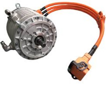 Hard to find except salvaged from wrecks, these are the goto for people that want to incorporate a custom solution into a similarly sized conversion. That is to say if you want to put a motor into a 3000 lb vehicle of roughly the same style as the motor from a wreck of a 3000 lb vehicle you can probably do it. The motors will be high voltage, high current, water or oil cooled, and have a special controller/inverter that checks, rotation, current draw, temperature, and other dynamics.
The one underlying thing that is emerging is that unlike ICE cars where demand for their engines is low, demand for the fuel left in the tank is non-existent, the electrics have high demand for motors, controllers, and Battery packs. This is because 1) they all are expensive, and 2) they last for years even decades. Being virtually a maintenance free system is quite different than their ICE counterpart which has thousands of moving wear prone parts.
The selection process
Many factors come into play in this process. Most focus on Speed, Acceleration, Distance, Charging, but those come after the computational work is done. For the motor, there are the factors of which type, how much voltage does it need, what is it's operational range (how many continuous rpms), how much current will it demand, what kind of load can it handle and for how long.
Then we have the drive coupling which can be gearbox, direct drive, transmission , and the coupling of the motor to the rear differential either directly or through a transmission/gearbox.
All this then has to be managed by the controller which must match the motor gearbox combo, and has certain demands it places on the required energy source (batteries).
Motor Starting Currents
Typically, during the initial half cycle, the inrush
current is often higher than 25 times the normal full load current. After the first half-cycle the motor begins to rotate and the starting current subsides to 4 to 8 times the normal current for several seconds.
How do you calculate the maximum current of a motor?
https://goodcalculators.com/motor-fla-calculator/
Motor Full Load Amperage Calculator
Number of Phases: 3
Motor Rated Voltage: V 230v
Motor Rating: 5 hp
Motor Power Factor: 0.91
Motor Efficiency: 85%
Results
Three Phase Motor Full Load Amperage (FLA): 11.96 A
Number of Phases: 3
Motor Rated Voltage: V 230v
Motor Rating: 4 kw
Motor Power Factor: 0.91
Motor Efficiency: 85%
Results
Three Phase Motor Full Load Amperage (FLA): 11.03 A
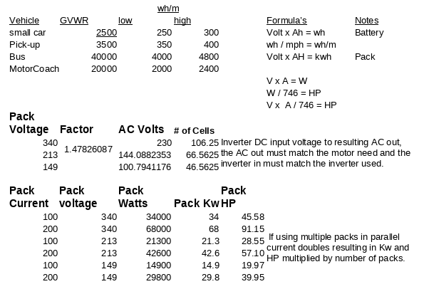
As the label suggests, wh/m is how many watts of power it takes to move a mile at a given speed.
If you use 250 wh/m @ 20mph = 250*20 = 5000w but if you use 250 wh/m @ 50mph = 250*50 = 12500w. They are both right. This is because at 20mph the motor does less work than at 50 mph.
So our 6800 lb Truck is going to require 680wh/m. But I picked something else from that video. The lecturer also made a point that it isn't just vehicle and contents but it also includes air drag, rolling resistance, and towed trailers.
An Inverter takes an Input voltage and converts that to AC 3 phase voltage. The motor you wish to drive from the inverter has to match the inverter output so to drive a 144v motor you need an inverter with 144v AC output. Likewise, a 230v AC motor requires an inverter with 230v AC output. This limits choices since Battery pack voltage = Inverter input DC and Inverter output AC = Motor voltage.
AC Induction motor basics:
Ac motors are the most common motor used in applications because they are AC and readily available. They run quietly and run a very long time and are economical.
All AC motors have same basic components:
1. A stator
2. A rotor.
The stator is the stationary coil that creates the magnetic field. This field reacts with the rotor bar to produce rotation. In 3 Phase, the stator sets
up a current and a magnetic field. The magnetic field causes a
rotation due to the 120 degree Phase offset. The current induced in the rotor sets up it's own magnetic field.
An important thing to remember about 3 Phase is they are offset 120 degrees apart and are self starting.
Slip: Slip is the difference between synchronous speed and actual speed of the motor. Induction motors rely on the slip to induce current in the rotor and the amount of slip changes as the load on the motor changes.
In order to change the
speed of an induction motor the frequency must be changed. This is accomplished with a motor control and the most common is a variable frequency drive or VFD. Without a VFD the motor speed is fixed by the equation 120 * Frequency / number of poles.
120 * 60Hz/2 = 3600rpm
120 * 60Hz/4 = 1800rpm
120 * 10Hz/2 = 600rpm
120 * 200Hz/2 = 12000rpm
So as we see here, the VFD control part of the inverter varies the frequency. In the first two examples there is no variance. so the motor always runs at full speed which is governed solely by the number of poles. Not what we want for an EV because we want to adjust the speed based upon the accelerator pedal.
So in the next two examples our accelerator pedal starts off at 0 and the motor is 120*0/2 = 0rpm. Then we push the accelerator down a bit and get 10Hz which spins the motor at 600rpm and we move. Then we push the pedal to the floor and the motor gets 200hz and the vehicle takes off like a rocket.
Two things things to consider is running speed and starting torque.
1. Running speed: this is determined by power supply frequency , the number of poles and the slip of the motor due to load. The specs will show the torque of the motor.
2. The starting torque is the chief limitation of the AC motor. If the motor must start with a load on consult the motor manufacturer.
Compared to single Phase motors the 3 Phase motor has a higher power density, greater starting torque, and more efficient than the single phase motors. They start on their own.
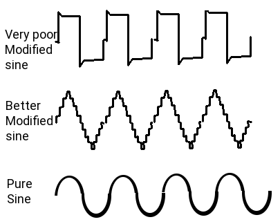 Lets add another cog in the design. We can have Modified sine wave inverter controller or we can pure sine wave inverter controller. The Modified Sine wave is cheap and does a poor job as it creates a shakey sine wave made up of almost square waves. These cause a lot of noise interferance effecting everything around. The pure sine wave (like you have in your house 120v AC lines) is a clean smooth sine wave with very little to no ripple. Pure sine wave inversion is far more expensive. Where the cheap inverter may be $30 to $90 the pure sine wave ones may be $350 to $19000. Also, the cheap one will damage any form of digital electronics like Laptops, clocks, radios, TV, and the noise harmonics can interfere with medical equipment even pace-makers!
As a general rule you select the battery voltage and amperage first, then select the motor that provides the drive range potential and adjust the battery packs to meet the motor needs. Then look for an inverter or build an inverter that satisfies the source input to the required output. We have the Battery plan at 384v DC @ 168A and have found siemens and motovario that supplies 230/400 motors in a large assortment of abilities. The 230/400 rating in general says it runs from 230v AC or from up to 400v DC under PWM or VFD or both.
The Siemens GP 1LE10 IEC-LV-Motor 1E2 seems to be a good match with rpms from 50rpm to 5000rpm. When you get to chapter 12 you will note that when they state the current draw it is based on initial instantaneous current at point of acceleration and not the run current. If the current was the run current maximum vehicle range at 46KW would be less than 2 miles. and we know that if we use 0.44 KWh/m which at 60mph would be 26.4kw in that hour. Current draw would not be 119A = < 2m range but in fact would be 5.98A
I told you this is a big topic or maybe I'm just wordy. We still have yet cover working with HP, Torque values, drag co-efficient, Kwh, Inverters, Charging systems, Distribution systems, Cockpit control and dash display systems, and ways to replicate electrically what was done using the ICE and it's mechanical systems. Then we can move on to actually doing the conversion.
Chapter 06 EV Inverters and controllers
Torque vs Kw
- Torque (lb.in) = 63,025 x Power (HP) / Speed (RPM)
- Power (HP) = Torque (lb.in) x Speed (RPM) / 63,025
- Torque (N.m) = 9.5488 x Power (kW) / Speed (RPM)
- Power (kW) = Torque (N.m) x Speed (RPM) / 9.5488
- Torque ft-lb = NM * 0.73756
- Torque NM = 8.86 * in-lb
Inverters
These are work horses of the electric vehicle. The motor inverters job is to convert the supplied power from the batteries to the motor in the
correct voltage, current, and frequency to drive the motor at a specific speed of rotation. The house inverters job is to convert the supplied power into pure sine wave 60Hz at the correct current for the coach living area on a motor home. A Car however does not need a house inverter.
On the driveline side of things, we have Battery condition monitoring and real time Battery capacity control, with voltage taps for 12.8v, 48v to run the needed systems. The traction motor, runs from direct inversion of 384v using VFD and PWM..
Inverter/Converter Tandem Units
An inverter/converter is, as the name implies, one single unit that houses both an inverter and a converter. These are the devices that are used by EVs to manage their electric drive systems. Along with a built-in charge controller, the inverter/converter supplies current to the battery pack for recharging during regenerative braking, and it also provides electricity to the motor/generator for vehicle propulsion. EVs use relatively low-voltage DC batteries (about 210 volts) to keep the physical size down, but they also generally use highly efficient high voltage (about 650 volts) AC motor/generators. The inverter/converter unit choreographs how these divergent voltages and current types work together.
Because of the use of transformers and semiconductors (and the accompanying resistance encountered), enormous amounts of heat are emitted by these devices. Adequate cooling and ventilation are paramount to keeping the components operational. For this reason, inverter/converter installations in vehicles have their own dedicated cooling systems, complete with pumps and radiators.
The basic EV
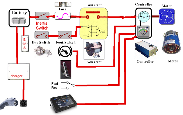 The diagram here is over simplified. It works as a working model for operation of an EV. If you used this model, yes you would have electric drive but at full speed all the time and once you are out of power everything stops. So we need to enhance the drawing.
You notice it is basically the same with the missing components now shown. The Inertia Switch stops everything in the event of an accident, The BMS protects the batteries from over charge and over draw, The recharger and port to restore the batteries, Accelerator part of the pedal to regulate speed, the dash to monitor speed and results, and the forward and reverse switch to choose direction of travel.
Additional to these systems, are the automotive systems for lights, braking, a/c, radio, cooling and steering. All of which are not shown on this depiction.
Ideally there should be cutoff switches between the battery banks
The contactor
This a
High voltage High current solenoid. It is controlled through a low voltage side operated by the key switch/foot switch. When you press slightly on the accelerator, the switch engages and if the
key is on, power flows to the controller through the contactor.
Inertia switch
Is a high current high voltage device that cuts power under abrupt impact.
It must be reset for power to resume.
Main Fuse
Has to be rated for the maximum Voltage and current and is designed to blow
if limits are exceeded.
Key Switch
Is the master on/off of the car.
Foot Switch Accelerator
Your dynamic speed control. The switch part enables the contactor to supply power and the Accelerator part says how much power to supply.
The Charge Port
This has both the supply lines to the charger a interlock switch to tell the charger external charge is securely attached. It is possible for there to be 2 or three charge connections depending upon design. You could have 230V AC @50A, 120 @ 30A AC, 115v @ 15A AC even some like 460V 600A.
|
Dash Display
Of coarse you want a fancy dash display that tells you how much charge you
have, estimated distance left, Pack condition, Speed and for the hot rod types, your rpm/1000. That last item is no longer required as you aren't needing to know at what rev you need to shift.
Manual transmissions are not found anymore in main stream life and EV's don't even have one most of the time.
Controller
Ah! the heart and brains of this outfit. The controller also known as the Inverter, after the function that it does. In the realm of DC motors these do not exist. But for AC motors they are the most necessary part. Types
range from the very trivial control to highly sophisticated ones. Basically, they take an input voltage range to produce an AC output range of voltage. Voltage controls the speed, well kinda.
In a flat inverter it controls the speed, but in a structured inverter, changing the output frequency can also be used to increase the speed. Current from the pack of batteries provides the torque drive.
Depending on the motor chosen for a given project, it may already come with a matching controller. You can use the supplied controller if one is given, or can also design and build your own. Most OEM's build
their own to their exacting specifications. But the design of such is a monumental task involving IGBT's to control high voltages and currents, fast switching and sensing devices and the like.
|
|
BMS
Essential to the health of the batteries is the Batteries Management System. It's job is to identify cells that are not as charged as others and balance things. It looks at temperature, State of charge, amount of charge or discharge in an effort to keep all cells in prime condition.
Charger
There are a wide range chargers and
charger designs. The charger must optimize the input power (AC) into (DC) known as rectifying it. Then charging the batteries from this rectified output. A good charging system will not allow the batteries to be over charged and will in fact shut off when they reach full charge. With Lithium Phosphate, you can not drain them more than 80% and can not charge more than 95%. To do so would damage the cells. Also take care considering fast charging. Charging at 4.2v per cell
is typical of BMS monitored and controlled systems but, and there is always a but, 4.2v will degrade the cells life. A smart choice is to charge at a maximum of 4v which can extend a cells life by more than 25%. Current actually does the charging. If cells are rated for 1A or 6A for example they should not ever be charged faster than that. This is known as the batteries 1C rating. fast charging charges at 2C, 3C, 4C. Some liFePo4 cells can tolerate 2C but not all. Even fewer can
tolerate 3C and none can tolerate 4C.
So consider this, you have a Pack that is 8 Gcells in series so you have 384v and your pack current is 600A and you are going to charge from an AC home outlet. So you have 120v @ 15A. You have an ideal Inverter charger that is very efficient and @ 384v has 5A for charging. This will do great and charge the pack over the next 5 days. Each cell is
happy because it gets 0.2 amps slow charge. But you get to a fast charge station 480v 300A fast charge and give it a wirl. The on board inverter converts 480v to 384v and gives it to the batteries. The battery packs are very angry with you. If the individual cells are 18650 they can handle 1 maybe 1.5A if they are 1.1A cells you are charging at 3C. if they 1.5A cells you are at 2C. If they are 32700 cells they are ok because they can deal with 6A.
The PWM Pure Sine Drive Inverter
The Pure sine wave inversion on the surface does a clean AC wave output to the motor. It gets it's cue from the Accelerator Potbox as to what the demanded speed of rotation is to be. It then needs to read the direction switch (FWD/REV) and use this to determine the frequency to deliver to the AC motor. IF 60Hz is the full on normal run speed of the motor at say 3500rpm, and you are asking for 200rpm then the pulse given to the motor 17% of 60 cycle per second. if I did the math right the pulse would have been .17 seconds.
Chapter 07 EV Truck Theory wrap up
Thus far we have examined the reason for going the EV truck route. You buy a new truck and drive it off the lot and loose 30% of it's value right off. After a few years you are lucky if you get 10% of what you paid for it. During your ownership you will have paid for your lifestyle with hard cash for fuel, oil changes, typical ICE failure problems that amount to major mechanical bills, tows, and expensive parts. In the end you spend roughly $50,000 for the vehicle, upwards of $4000 a year for upkeep, another $2000 to $6000 a year for traveling, and if you hang on to it for 5 years that's in excess of $80,000 and you might get $5,000 trade in. In the end you are out of pocket $75,000 for 5 years (15,000 a year). Your next 5 years you can expect the same.
Based upon research, the truck you own or are currently financing might cost you $30,000 for conversion, spent another $500 to $1000 a year for operation if you are unlucky and was charged for power. So your first 5 years cost you $38,000 and instead of trading in you go the next 5 years for $5000. Being frugal, you put away money in the bank as if you were running a gas hog and have $20,000 that you can use to at the end of the second 5 years to replace the batteries that need replacing. Your yearly cost of ownership averaged over 10 years is $4,300 and the vehicle owes you nothing and you are debt free. Without conversion you have diminishing trade-in value and payments on another 50,000 plus a yearly cost of 6,000 or so.
We examined the chassis and discovered we can remove 490 lbs from the old ICE system. We have now got roughly 8 cu ft of space for our EV Batteries. But have a constraint on how much weight we can add in batteries. In speaking of the batteries we have 4 basic types of battery topography that we can use. Three of the 4 topographies allow us to match and control quality of components for the highest in use life. Removing the complexity of the ICE has reduced us to having a maintenance free motor good for 1 million or more miles, a traction drive inverter, a cockpit control system and 2 Banks of batteries for which we know each and every part of the system. If a cell dies we are left with a still running vehicle but the ICE owner can have thousands of possible failure causes in his system. Check engine light doesn't tell you much does it?
Looking into our drive train we discovered that our unit is 1/8th the weight of a Motorhome and smaller in size. The Kwh/m was determined at 1/10th the GVCW and total KW = V*A, Electric HP is much less in requirements than an ICE needs and if we prevent shortened battery life by charging at too high a voltage or current we can extend our batteries useful life.
We dove into the basic theory of AC motors and outlined how AC motors work and why they are a good choice. How to use them in a variable speed set-up rather than to just full on drive to their maximum and keep them there.
Finally, we discussed the inverters and converters that we will be needing and
constraints we need when talking about the different purposes. How using a single 384v battery source can satisfy providing for 12v systems, 5v systems, High voltage systems for drive operation.
I think we are now ready to go to the next step and define the systems for real.
Chapter 08 EV car Basic System
The Truck will retain almost none of the electrical systems it once had. We will keep the wiring to the lights but install new lower powered LED lights. Keep the fuse box but repurpose it. Keep the stearing column and all it's controls. The existing system is basically the inertia switch main contactor and the brake and e-brake pedals and the new system (inside the brown borders).
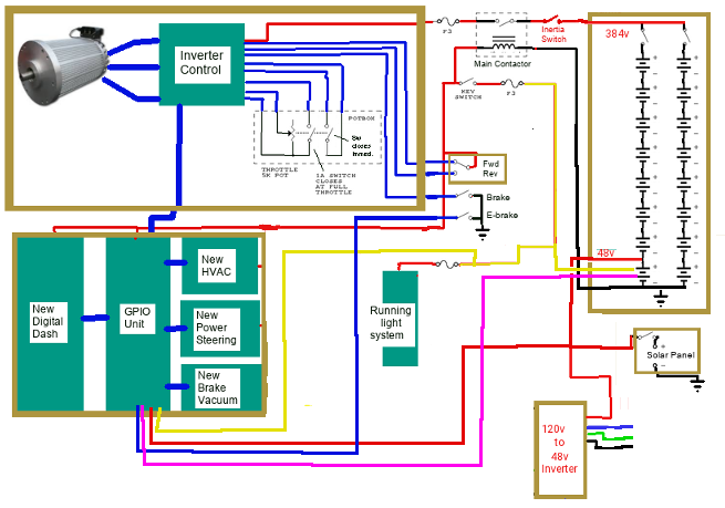 So moving left to right top to bottom we have:
- *New Drive Motor, Drive Inverter,Accelerator Pedal ***it replaces the gas ICE engine and all that went with it.
- Main contactor & inertia switch, Driver control, *New Fwd/rev switch, Brake pedals ***adding a FWD/REV switch.
- *New 16x 48v blocks making 2x banks at 384v, ***replaces the Gas fuel tank.
- *New 48v, 12v taps, *New 57v Charger, *New 480 watt 57v 4A Solar array or better
- *New Dash Display, computer, GPIO, HVAC, Pwr Steer, Brake vacuum ***Cockpit control system & implements replacement systems for HVAC, Steering, Brake vacuum.
- Running lights ***Kept as is.
- 120v Shore charger.
Wiring and feature pre planning
The concept here is to have an all purpose universal automotive controller and computer that can accommodate all vehicle classes from the sub-compact to the large scenic cruiser buses and Motor homes. To accomplish this the dash display has a credit card sized computer on it's back and this computer wires to a base board just behind it. The function of the base board is to supply power to the function boards, pass information to and from the computer to the various function boards, link the radio, GPS and phone into the system, and establish charge/discharge monitoring. Above the base board is 3 output modules, 2 input modules, and one analog module.
Lets start with the Raspberry Pi 3b computer. It has a 40 pin GPIO connector and we have 16 connections from the computer in use. The 16 wires pass to the 16 pin computer connector on the base board. 4 of the 16 wires supply the power, 2 operate as an I2C communication to the function boards. 4 supply notification of input changes, one supplies real time speed of motion changes, and 4 are informing the computer about battery discharge and charge status.
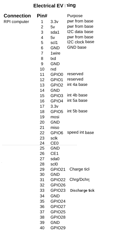 Now on the base board we have a power connector, followed by an ignition switch connector. The ignition switch turns on the system and once started it cannot be shut down until the computer says it's OK. Next we have the charge controller connector that wires to the rear charge port. Then we have a speed sensor connection. The speed sensor wires to a magnetic or optic sensor on the motor shaft. An I2C connector connects to 3 modules for radio, GPS, and Phone. Lastly, there are two connectors to the feature boards. One is 11 pins and handles all inputs to the system, the other handles all outputs and is 14 pins.
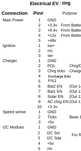
There are 3 output modules that are at addresses 0x20,0x21,and 0x22. There are 2 x 8bit channels per module.

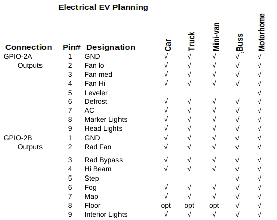
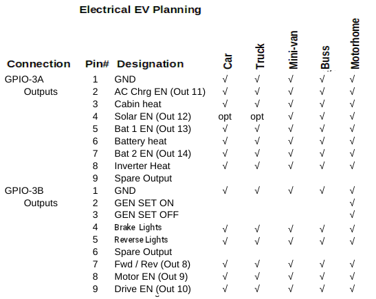
Board one is GPIO1 with channel A being mirror control and channel B being window control. Where there are provisions for two mirrors, there is provisions for left/Right front and left/right rear windows.
The second module mounts on top of first one and except for address is identical to the first. You will note that depending on the vehicle class not all bits in the channels are used. Channel one handles fan speed, defrost, AC, turning on/off the lights and in the case of motor home the leveling jack power. The second channel controls the rad fan, and rad bypass to help control motor cooling, more lights, and in the case of a motor home, the entry step.
The last output module again is at a different address but this time has marks like (Out 11) that identify output states that either go to the ADC board for motor control or to the base board for charge control. Channel A handles charge Enables and cabin, battery, and Inverter heating (for cold weather). Channel B has provision for a Gen Set on a motor home, and motor related Enables. and that's it for outputs.
Drive-En has special meaning. First this signal in software prepares the vehicle to be driven. The control signal passes to the traction inverter to turn it on and it also enables the brake vacuum pump, power steering pump and h20 pumps so they are ready as soon as there is a call to move the vehicle.
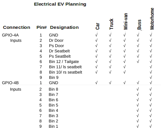
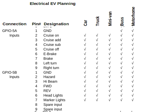
Board 4 starts the input side of things. Channel A informs the computer of the status of doors, seat belts and bin doors. Channel B deals entirely with bin doors.
Board 5 is the last input board in terms of digital inputs. It wires to the cockpit switches for Cruise, brake and E-Brake, left turn, right turn, Hazard, hi-beam, headlight, marker lights, and the fwd or reverse switches. If the gear shift is in neutral or park it is neither fwd or reverse.
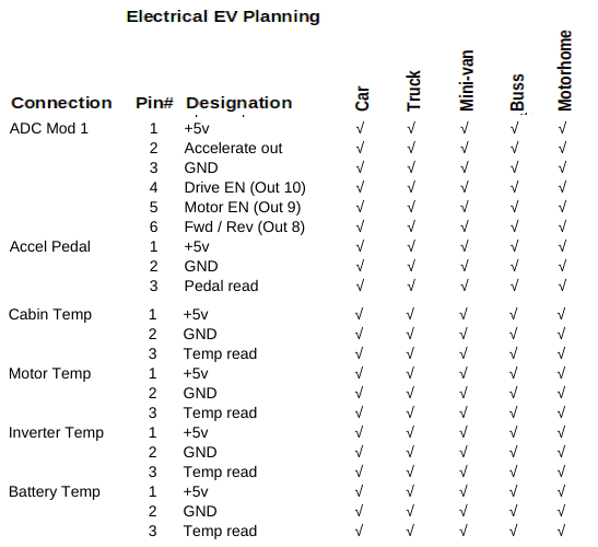
The final module is the ADC module with reads the accelerator pedal, the battery voltage and the temps on one side and controls the motor Inverter on the other side.
Canopy Systems
The cooling, steering, braking systems and lighting management resides up front in the canopy along with the Motor and Inverter control. As designed, we have Motor Control (Drive-En, Motor-En, RPM value) coming from the ADC board. We also monitor Inverter and Motor temp from the ADC board. We can control the Rad fan and Rad bypass using GPIO-2 outputs and can also heat the Inverter and Motor using GPIO-3 outputs. The base PCB collects rpm ticks from the sensor on the motor shaft.
GPIO-2 supplies Left-turn, Right-turn, Markers, headlight, Hi-Beam, and Fog lights. These signals are designed to operate 48v 0.02A LED light systems. If the plan is to use 12v incadencent bulbs, 10A relays will be needed. The steering pump, brake vacuum pump and water pump must connect to 12v using Drive-En signal so that operation is on when intending to move the vehicle. The headlight and high beam must use a relay. If motorhome application, the leveler output also needs a relay for the leveler pump. The Brake lights and reverse lights and trailer lights, while not part of the canopy systems will be in the canopy. We added an output to the above specs for sending signals to turn on and off brake lights and reverse lights. In an ICE design water pump, brake vacuum, and pwr steering are the result of the Engine running and in our case will be the result of Drive-En signal since the motor only turns when moving.
Cockpit Systems
In the cockpit with the driver will be the brake (and switch), E-Brake (and switch), Key switch, a Forward / Reverse switch, and the Potbox (accelerator). None of the high Voltage or High current comes into the vehicle. The dash computer monitors everything. The ignition is locked to on even if the key is removed. If an incorrect password is entered 3 times the computer will issue a shutdown. If the vehicle is in park and the operator selects shutdown it will also shutdown. We need to lock the ignition on until the computer says it's ok to turn off the system. At back we have charge control and Batteries and on the roof the solar arrays. Here to we need more signals. To charge the 48v battery blocks we have a Charge-En but now also need 8x48v blocks in series for 384v and in parallel to charge them. We can do this with a switcher board.
Items not yet incorporated in the design include keyless entry, cylon eye and electric door locks. Keyless entry and door locks will not be incorporated. Keyless entry needs the computer to be on 24/7 which is a power drain. Adding door locks requires an additional 2 to 4 signals. The cylon roaming eye is a novelty add-on. An anti-theft security system also would need to be an independant Add-on since we don't want to drain our batteries needlessly.
In an ICE the PCM (power control module) runs from the 12v battery 24/7 and typically draws 0.2 to 0.5 amps continuously. This has been a problem for years as a 65Ah battery with this constant drain can be depleted in as little as 130 hours of not being started. The PCM handles locking doors, unlocking doors, keyless entry, courtesy lights, and security systems. Being an EV we also have a problem since we can't start the vehicle to recharge the battery we would need to charge from solar or some land based power outlet.
Chapter 09 EV Truck Convert: Cockpit and electronics
The new Cockpit:
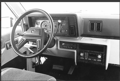 becomes ...

The mock-up picture at the top of the page gives the basic idea. With a digital dash, a touch display that is easier to see replaces the mundain grey on grey instrument cluster. The center section is removed as the radio and heating/cooling is handled electronically. Essentially, the entire Dash instrument cluster can be run and tested as a self contained system. We will replace the accelerator with a pot-box foot operated potentiometer, and we leave the brake pedal and E-Brake pedals as is. We lose hundreds of wires to give a nice clean and clear compartment. So for starters we will build the Dash instrument cluster as follows:
Digital Dash
We want to make a New Digital Dash for a vehicle. So what sort of things should this Dash have. For ease of viewing it should have at least a 10" HDMI displays and full computer control. Obviously it needs to have adjustable brightness for bright daylight and dark night driving. Being 10" displays they will be 8" wide and 6" tall and sit back from the driver. It should control most if not all driving seat adjustments, so it needs Radio control with volume, station, and balance, Heating and A/C adjustment, Mirror adjustment, Pre driving system checks, Back-up camera with rear view capability, possibly a front view dash cam, and be fully Electric Vehicle capable. Optional would be GPS navigation, Bluetooth connectivity for hands free phone use. That's a pretty tall order but lets see what we can do.
Choosing to have full computer control is most likely to use a Raspberry Pi 3b+ as it has a lot of functionality and is small (credit card sized). A USB mini keyboard gives us the ability to make direct system changes should the need arise. Our Pi computer would mount to the back of the display and light sensors mounted into the frame surrounding the displays would give us the ability to control display brightness automatically. Forward facing dash cam is no problem as it can mount to the back and plug conveniently into Raspberry Pi.
I2C is a two wire communication protocol that can access and control roughly 128 devices with many of them handling many different functions. So as not to overload the storage capabilities of the Pi, we will use an external usb harddrive for all footage from webcam and Back-up/rear view camera's. Now we will look at how we can implement all the features by the PI computer.
Universal EV conversion
Lets take a look at it from an
operators standpoint. We need to know our speed and whether it is Kph or Mph. The old way was to have a cable from the transmission to the speedometer. The speedometer updated a mechanical odometer in Mph only. A moving needle rotated around to point to tiny numbers. Newer versions used a sensor and moving coil meter in much the same way. And the newest of vehicles have custom dash with speed readout and digital odometer.
Our dash display is a 10 inch touch screen. In the center is a speed readout with numbers around the perimeter. As speed increases the number background turns from Grey to green. two buttons below the speedo select Kph or Mph and automatically adjust the speed numbers and readout to match.
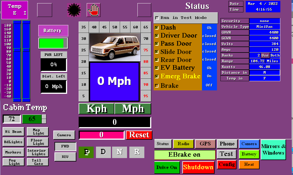 Above the speedo is left turn and right
turn indicators and the current state of the headlights (
on/off/hbeam) and whether cruise is on or off. A Trip odometer and trip reset is below the odometer. Being an electric Vehicle we don't use a gear shift in the usual manor. It's all Electronic. When Ebrake is ON you are in Park. When off you are in neutral. When stopped you can use a switch on the dash to select FWD/REV or the touch screen to switch from FWD or REV. Being an EV means we need to know the state of the Battery and the Inverter temps and Motor temps. Top left shows this.
Under that is the current cabin temp and desired cabin temp. And below that we have buttons to control lights using the touch screen.
Above the speedo is left turn and right
turn indicators and the current state of the headlights (
on/off/hbeam) and whether cruise is on or off. A Trip odometer and trip reset is below the odometer. Being an electric Vehicle we don't use a gear shift in the usual manor. It's all Electronic. When Ebrake is ON you are in Park. When off you are in neutral. When stopped you can use a switch on the dash to select FWD/REV or the touch screen to switch from FWD or REV. Being an EV means we need to know the state of the Battery and the Inverter temps and Motor temps. Top left shows this.
Under that is the current cabin temp and desired cabin temp. And below that we have buttons to control lights using the touch screen.
To the right is the main
menu. It allows you to select different features using the buttons at the bottom, Right now the status display is showing results of the system test. It verifies that it is OK to use the vehicle. One might ask why do we need to verify it is OK to use the vehicle. The answer is simple. The system checks that the dash control system is working, Seat belts are buckled, and the doors closed and eBrake applied before it will allow the motor to function. It is more informative than a check engine light and buzzers. Later you will see how it plays into doing self repairs. For now let's assume it all is OK and so we select Drive On.
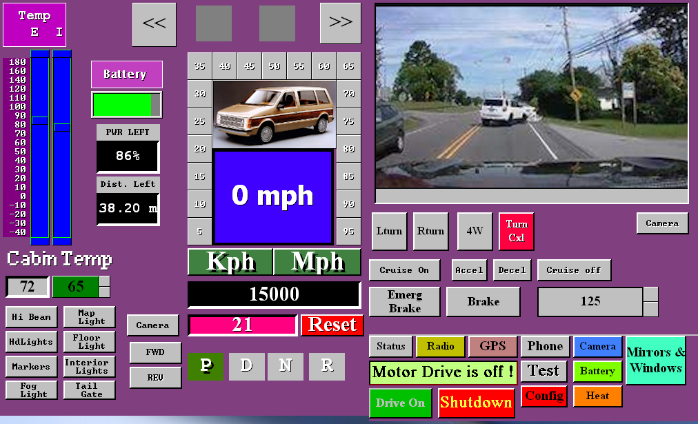 The right side changes to the drive screen. At the top is the Dash cam/Backup cam display. Using the Camera button below the display you can view the Dash cam/Backup cam/Info displays. There are also touch buttons to turn on or off Turn signals, Hazard flash, Brakes, and Cruise control. While you still have all these in the car, you may use either the car provided ones or the touch screen ones. In test mode, you can use the Accelerator at the bottom without actually operating the motor.
There is a Credit card sized computer on the back of the 10 inch Display. It costs an amazing $45 or less and is the heart and brains of the Vehicle. It takes automotive controls and user actions to control the whole vehicle through a simple single board controller I have designed. But more on that later.
Power first. We need a Battery system that has a certain voltage, specific Amp capacity, which based upon the formula V*A=W we can determine watts of the battery. Using the GVWR or GCWR we can determine the distance we can go. W/1000 = kw, and GVWR/10000 = kWh or kilowatts to move a weight per hour on flat even ground. For my Motor home it was 17500lbs/10000 = 1.75kwh per mile. A car as above is 4000/10000=0.4kwh/m. To deal in KMs take 20*m/12=km.
So for my Motor home I planned 2 banks of battery at 384v @144A = 55.25kw per bank. 2 * 55.25 = 110.5kw and so @ 1.75kwh/m I should be able to go 65 miles. I used 2 banks because if a bank goes bad you need the ability to keep running and 2 bank @144A = 288A and each bank is lighter. For the Truck we hope to use 2 banks of 84A each = 384v @168A = 64.5kw, 64.5/0.68=94 miles to a charge.
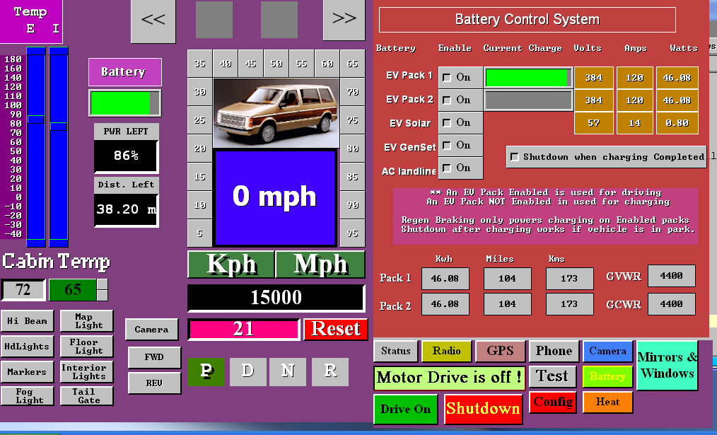 Charge in and out of the battery is measured in coulombs. 3600coulombs = 1A. So the computer reads the amps per second going into the battery or out of the battery system. It can update in real time the amount of battery left and how much farther you can go. Solar panels on the roof charge the system when there is enough sunlight. For the Motor home it had 57v @ 20Ah charge and for a mini van it can have 57v @ 4Ah of charge. This means a Car would take 8.6 hours. But and there is always a but, both have onboard charging from standard house current so from 120vAC @ 15A = ~37A so the Car improves to 2.35 hours. Changing the charger to run from 230vAC cuts the charge time in half. Tesla charge stations are rapid but risk charging so fast that the batteries can become stressed and fail early.
Not to fret, most people travel less than 50km in a day and if we go with figures used by the insurance bureaus to compute insurance, 20,000km/y = 54km/day = 33m/day = 40% use or 2.5 hours charge time needed per day.
For the battery screen we can use battery pack 1 or 2 or both for use in driving. If not using both, the non-enabled one can be solar charged while you drive. Enabling solar charge works if there is enough sunlight. And of course there is 120v AC charge when parked. Selecting shutdown when charging is complete only works on a parked vehicle so you can set to charge while your shopping or at work and the system will shutdown unattended. Ideally, you would disable both batteries for driving and choose Shutdown when complete which disables all vehicle operations during the charge cycle. The values shown on the screen actually come from the config screen. They change as conditions change.
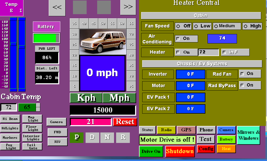 Next up is the heater control screen. It allows changing for comfort and checking on the health of systems.
Comfort wise you can set fan speed, AC on or off set your desired temperature and choose between degrees in C or F. You can view the temps in the battery packs, motor, inverter. In cold weather the EV systems need heat for optimum functionality until their self generated heat gets too hot then the cooling systems come on to cool them down until they reach minimum ideal temperature.
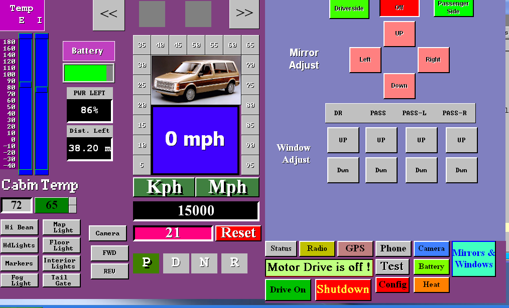 Self explanatory here. You press a button to move the mirror to the desired state. Likewise you can open and close 4 different windows.
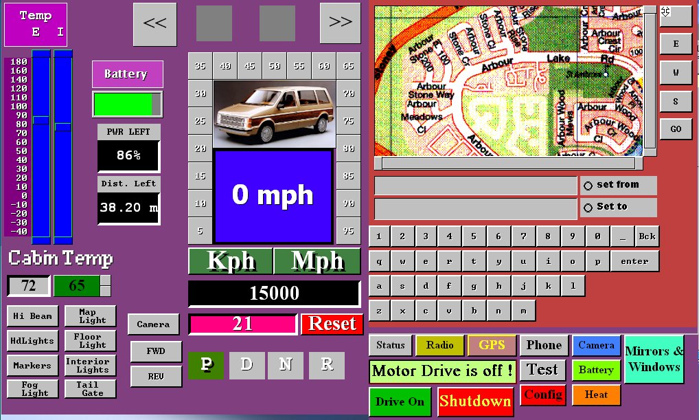 Here is a computer control of a Navcon GPS system at the top is the selected road map with map adjustment below. Under that is where you state your starting address and ending address using the provided keys at the bottom. The map shows your start point and end point when your current position allows them to show. Your current position always shows center unless you slide the map using N E W S keys.
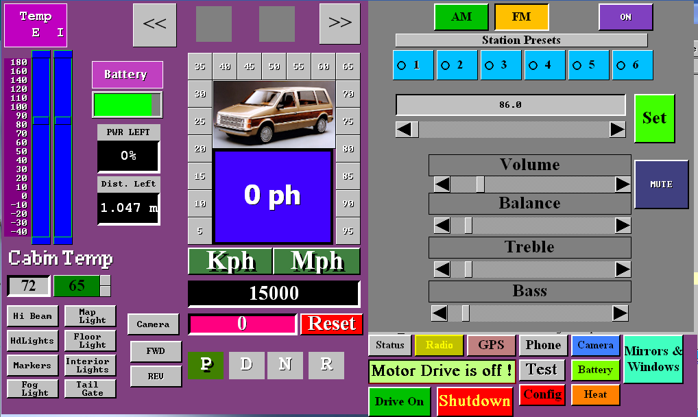
No presumption about there being a radio or not. Using a built in radio module and amplifier operated by this touch screen display, all you add is speakers which usually exist in any donor car being converted.
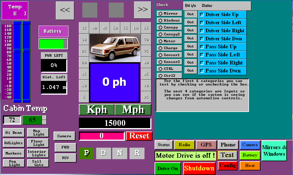 Imagine if you will, on your current vehicle, you have a check engine light, battery/alternator light, temperature light and sometimes a little door open indicator. If something goes wrong you need to go to a garage and pay for them to use a OBDCII to read cryptic error codes and reset them after fixing the problem.
This EV Dash has built in TEST and Report facility. The report facility just tells what the current detected states are. The Test facility here allows you to see 10 categories on the left with currently the window up/down set showing. It is a work in progress as I refine software to match the actual electronics.
By turning on and off the checkboxes you can confirm that the desired action is being done like moving the mirror left or right or up or down. Turning on or off the park lights, headlights, or seeing that when you press on the brake pedal the automotive control boards sees it. You are having trouble with cruise coming on when you ask for it. So you come here select CTRL (control) and see if the cruise on indicator is on or off. Press Cruise on the steering wheel and see if it shows you pressed the button. If there was nothing happening, check the other cruise related buttons or turn signals or hazard and if they are all dead the cable is likely unplugged. If only one is not working it is likely a broken wire or bad switch.
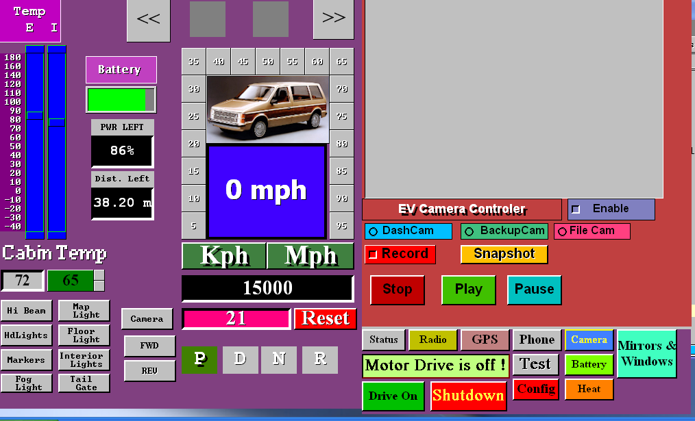 Then we have the camera screen to be used only when stopped. If you want to use it while driving, you can’t because that is a huge safety issue.
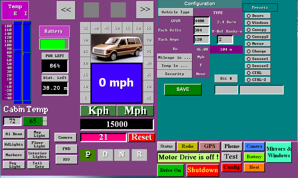 Two more screens are present but not yet functioning. One is the phone and the other is the Config screen. phone would connect to your phone by bluetouth and config allows all the presets to be set.
Electrical Systems
The electrical systems of an EV conversion encompass several interconnected things. At the helm is the computer controller which in this case is a Raspberry Pi 3b credit card sized computer. This computer connects by 16 wires to a base PCB. The base PCB also obtains power from the battery packs, and has connections for ignition switch, charge control, RPM tick sensor, I2C accessories, and the input, output, and ADC bits arrays. There is an on board I2C level shifter for comunication. The inputs and ADC bits are provided on a 11 pin header and the outputs on a 14 pin header. As such the first part of the system is the computer and the base distribution system.
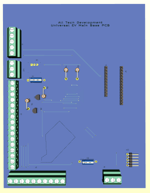 To the left is the base PCB. Below are the input and output modules that sit above the base.
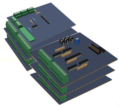 There are two input modules and the ADC module in the first stack and three output modules in the second stack. All connections to the modules are at the face edge to the automotive functions they go to. Two headers are on each of these boards. One goes to the previous board and one to the next. So base 11pin connects to input board 1. Input board 1 (second connector) goes to board 2. Board 2 (second connector) goes to ADC board. On the output boards they inter-connect in a similar fashion.
In such a manor, we can have the entire electronics distribution system in a box about 9" x 6" x 4.5". This makes up the second part of the system. In the engine canopy we have Motor, PWM Inverter, canopy controller, and sense passthrough. The Charge controller mounted at the back of the vehicle which manages 120 AC charge and Solar charge, and finally the batteries with BMS and switching charge control.
Raspberry Pi 3b computer
This tiny but powerful little
computer has 4 usb 2.0, I2C, SPI, RxTx comunication, Ethernet, a 40pin GPIO connection and HDMI is where we will be most concerned with.
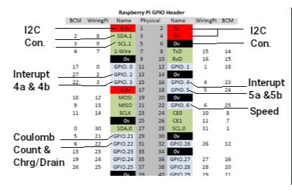
Because we added 2 banks of battery, we needed to add a second set of Coulomb Count & Chrg/Drain leaving just 5 GPIO unassigned. A front facing CCM camera connects to the CCM port to provide a dashcam and the rear backup camera talks by bluetooth.
The Raspberry Pi 3b 40 pin GPIO connector is a very powerful tool in my design. While not all the pins can be used and several are duplicates, there are 17 available and we are only using 7 to 9. The breakdown is as follows:
- 1,17 = +3.3v
- 2,4 = +5v
- 5,9,14,20,25,30,34,39 = GND
- 3,5,27,28 = I2C#1 &
I2C#2 we are using only I2C#1 @ 3,5
- 7,19,21,23,24,26 = SPI1 & SPI2
- 13,15 = int4a int4b
- 16,18 = int5a int5b
- 22 = rpm sense
- 29,31 = charge / discharge counting
- 8,10 = Rxd Txd
- 11,12,32,35,36,37,38,40 = GPIO unused
The RPI is powered by the Base PCB that is handling all
comunication to the various systems. I2C provides communication to the various systems with pins 13, 15, 16, 18, 22, 29 used as interupts for input changes (int4a int4b int5a int5b), rpm sense, and charge/discharge ticks. pin 31 tells the direction (+)=charge (-)=discharge. During programming the EV system the first of 4 USB ports attaches a keyboard. A second USB port is used for the back camera recording to a flashdrive. The HDMI attaches to the display and a 3rd USB provides touch screen functionality. The DashCam connects to the CCM camera connection. The rear camera is still being worked on.
Base module
Observing the images below, we can see the base top view, left edge view, and front edge view. Left side back is the power connection with GND, +3.2v, +6.4v, +12v, and +48v. Moving forward we have the ignition switch which turns on the whole system. Ideally the ignition once activated only turns off under computer control. If shut off before the vehicle is safe to shut down, it holds power on until given a shutdown command. Our next connection goes to the Raspberry Pi 3b computer. The last view has the charge controller connector and the RPM sense. Far right is the I2C carry on connector pointing off the right side. This connector is used to add GPS, Bluetooth, and AM/FM Radio to the system.
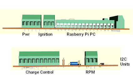
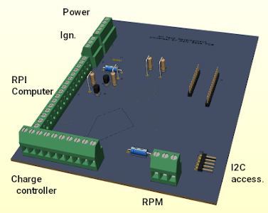
PCB prints and schematics are available in a separate service booklet.
GPIO - INPUT modules
The input modules have 16 inputs per module. The first module is at 0x23 and the second one is at 0x24. Each module has a single mcp23017 GPIO-expander chip, with selectable addressing. All connectors have pin 1 designated as the ground pin. The Input boards have a 4 pin connection on the side that provides GND, +5v, +12v, and +48v just in case the need arises. The first input module (0x23) handles seatbelts, doors, and bins. If a door or bin is open that input is grounded. If a seatbelt is unbuckled it is
also grounded.
The second input board connects to the steering wheel cruise control switches, the E-Brake switch, the Brake switch, the left turn, right turn, hazard switches on the column, hbeam, Fwd, Rev, headlight and marker light switches. The switches are actually repurposed to simply toggle between +5v (off) and Ground (on) to tell the computer what the operator has selected. The output board does the actual activating of the feature based upon user manual controls or touch screen selected operation.
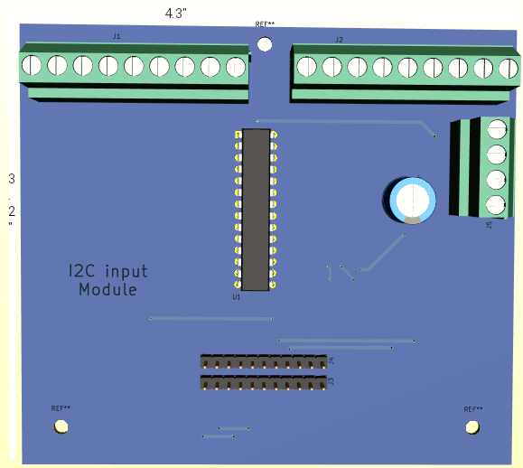
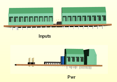
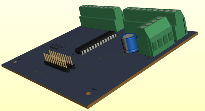
ADC module
The top board on the first stack handles ADC operations. These operations are handled by two IC's. Address 0x28 is the accelerator output to the Motor controller. and address 0x48 is the one that reads the Battery voltage level, Temperatures of the motor, the Inverter, the Batteries, and the cabin. It also reads the accelerator pedal. This gives the computer the means to have both manual and cruise control, and keep the operator informed of the temperatures, and charge state in real time.
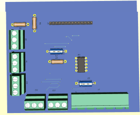
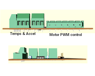
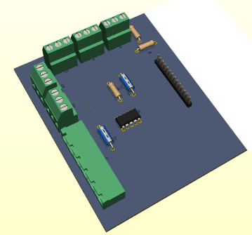
A DS3502 (0x28 address) 7bit digital potentiometer presents the desired speed value to the motor controller. This value is either the value obtained from the accelerator pedal reading or the value set when cruise is enabled. Let us say that 8000 rpm is full speed from the motor and results in 66mph. This potentiometer has 128 increments so when the value is 0 (the first increment), motor rpm = 0 and speed = 0mph. When the value increases to 1, rpm increases to 62.5rpm and speed = 0.51mph. This is of course governed by 3 factors provided by the computer. These factors are DriveEn which powers up the Invertor, MotorEn which allows the motor drive to function, and lastly Fwd/Rev which determines whether to move forward or reverse.
The ADS7830 8 channel Analog to digital converter, supplies the computer with the battery voltage in the range of 336v to 384v, 4 Temperatures in the range of -60 to 200 degrees F for Motor, Battery, Cabin, Inverter and the read accelerator value 0v to 5v. Each value is in 1024 increments such that battery voltage is in 0.375v increments, Temperatures are in 0.2539 degrees F, and accelerator is 0.00488v = 1/8th of 0.51mph per increment. The computer basically just divides the accelerator value by 8 such that any value below 0.039 = 0.
GPIO - Output modules
The output modules are far more complex than the input modules. While they still use the mcp23017 chip, with selectable address 0x20, 0x21, and 0x22, they also have optic isolators and pull-up resistors. The expander chips have limited ability to drive heavy loads so the isolators provide both heavy load capability and increased voltage to feature capability.
For example, the automotive
mirror up-down-left-right motors run when 12v is across the windings. The computer commands using 0v or 5v which won't do. So the opto isolator allows the computer to control using 0-5v and the opto drive to use 0-12v. In essence, we get control using solid state rather than relay driven circuits.
So board 1 is Mirror and Windows. Board 2 is climate control, leveling, and lights. Board 3 is Generator, Drive heating, charging and enabling. There is provision on the board for running the interior fan at 3 speeds for board 2. For board 3 there is provision for a DIP switch to pass Enable signals back to the Base board and subsequently the computer. A Car doesn't use all the outputs. They are there for the Motorhome which needs Leveler control, Entry Step extend and retract, generator start/stop, and so forth. I suppose a Car with a handi-cap Entry Platform could use the leveler or entry step to extend or retract a ramp or lift.
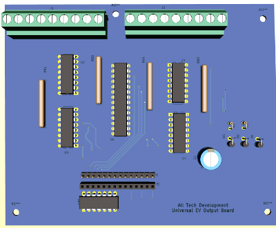
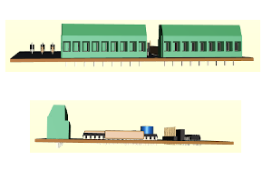
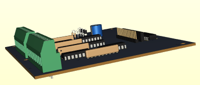
The output boards are 5.2" wide and 4.4" deep. As it stands, the use of LED lights for markers, brakes, reverse, and signals can be easily accommodated without extra provisions. Headlights are the ones that will need an extra relay. Interior lights, fog lights, maps lights and floor lights can also be LED so don't pose a problem.
EV Connections
Starting with the Dash, Remove the instrument cluster and modify the dash for the 10" HDMI touch display. Mount the raspberry pi computer to the back of the display. Connect the HDMI cable to the display and raspberry PI. Locate and wire the ignition switch to the base PCB and connect the cable from the raspberry pi 40 pin connector to the base pcb. At this point supplying 6.4v of power to the power connector will allow programming the raspberry pi and testing the raspberry pi comes on with the ignition switch.
Connect input boards and output boards as indicated. The whole system can be tested at this point. You are looking for input changes to cause interrupts and touch screen actions like turning on and off lights, fan, AC, etc. to result in output state changes. For example see if a pulse shows at the window up/dwn when you try to open or close a window.
My intended frame work consists of 'L' shaped frame that the display mounts to with the raspberry Pi mounted to the back of the display. The base PCB mounts to the flat part of the frame and connects the to the raspberry Pi 40 pin connector. A 'Z' style frame mounts to the back of the first frame such that the input and output boards can mount to it. At this point you need to deside if you want connections to face back or forward and mount the boards. The two ribbon cables from the base PCB need to feed from behind the Z-frame if the i/o connections face forward, or can pass to the boards from the front if connections face the rear of the assembly.
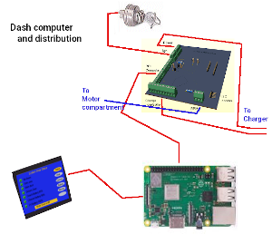
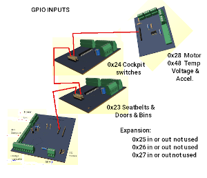
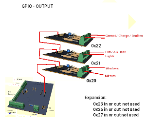
There are 110 wire connections going to the various systems of the EVehicle from the input and output boards. My preference is to wire from the boards to a plate with barrier strips on it organized into purposes. Like put two five contact barriers. Wire the 9 pin mirror wires two the two barriers. Now two cables of 5 wires can go to the drivers door and passenger door to connect the mirrors. The same goes for window up and down. Use four three contact barriers supplied by the 9 pin window connector. A 16 contact barrier will suffice for the seat/door/bin inputs.
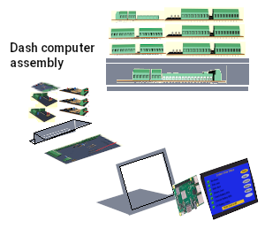
 Three different sizes of display to fit any vehicle.
Systems after this point at not in the cockpit they reside in the canopy, back of vehicle or at various light sockets
EV Charger
The charge controller takes
direction from the dash computer and the AC charge port. The computer provides 4 enables (battery pack 1, battery pack 2, Solar, and AC charge). At the AC charge port there is a microswitch that is activated by inserting the plug into the port. When AC shore power is plugged in, it converts 120v AC to 60v AC and if the computer has issued a 'charge-enable' signal passes that AC voltage on to a full wave bridge rectifier to produce 57v DC for charging. As long as the AC charge cable is plugged in normal vehicle operation is prohibited.
Roof top solar panels supply
power when there is sufficient sunlight also to the charging system. It can also be enabled/disabled from the computer. The 2 battery pack enables determine which battery pack(s) to use.
It has two coulomb counters. One monitors charging at 57v and the other monitors 384v discharging and regen charging. The charger also handles switching 48v blocks into series for run mode and parallel for charge mode.
Engine compartment (Canopy):
We don't have a clunky engine and transmission so what we are left with are, a wire cable from the battery 384v supply, and a lighter power cable with +48v, +12v, +6.4v, and ground. This lighter cable then splits with one part going to the dash computer and the other to the board depicted below. A 20 pin connector from the computer then wires to this board.
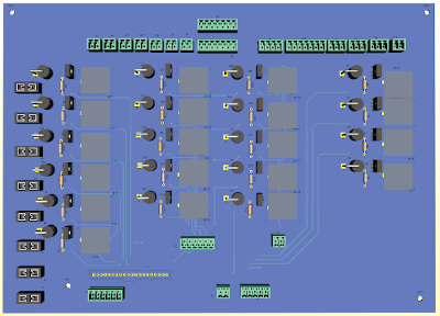
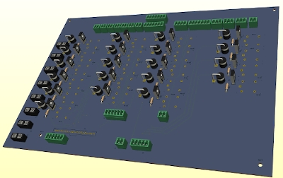
Down the left side are 8 fuse holders, then 6 relays with their driver circuits. These handle the Rad Fan, Coolant Pump, Coolant bypass, Brake vaccuum, Power steering, Inverter heat, Motor Heat. Moving to the right is 5 more relays with drivers that handle The vehicles lighting needs if you are using Incandescent bulbs. If you are instead using LEDs (recommended), these relays and their circuits can be left out. Then to the right of that are 5 more relay circuits for towing a trailer. They are also not needed if you don't want trailer towing. The last 4 relay circuits are needed for the headlights, Hi-Beams, Fog lights and leveler jack if a motor home application.
EV PWM Motor Inverter & Motor
The inverter uses the 384v and Ground from the main battery and control from the ADC board. The control is a combination of 2 temperature sensors, a speed (RPM) sensor, a digital speed request, a direction request and 2 enables. The motor enable activates the Inverter placing it in either run or standby. The drive enable turns on the inverter circuit. So with the inverter turned on (drive enable), the inverter goes to standby and presets motional direction to either FWD or REV then begins sampling the digital speed and motor enable. Upon seeing motor enable the inverter generates the PWM and or VFD at the 3 phase motor field wires and motion begins at the requested level.
Chapter 10 EV Truck Software
As you can appreciate, there was a lot going on in the motor home. We are now dealing with a Truck. We no longer need 2 computers but it still needs the combinational drive and accessory one. We will make use of software structure to gain advantage in the control of the EV.
The Operating System
The Raspberry Pi uses an ARM processor running a varient of the Linux operating system. It has all the physical features needed, USB, HDMI, GPIO, I2C, 32GB memory and runs Linux as the OS. Ideally, we could use a PC with Linux to develope the app then cross compile x86 to Arm64 to make the final app for the RPI. The most efficient is assembly langauge and produces the smallest and fastest code possible. Python, C and C++ but there is very little documentation on using it with GUI's like opengl and qt or gtk. At the other extreme we have xBasic that is powerful and easy to implement and writes the assembly code for us. We can use 'C' routines for GPIO and I2C operations and it handles Event Driven Programming (EDP) of a GUI with ease. Unfortunately, xBasic won't run on modern Linux because of Dll hell. It works fine in windows based OS but without GPIO and I2C features.
With Glade we can make a great UI but is very slow as there is no drag and drop widgets. As a work around I made a program in xBasic called MakXml.exe for windows. It can take our fancy UI designs and coding in xBasic and create the Glade UI file or a qt UI file for the GUI stuff and then build a basic structured python or 'C' binding. Once done, Glade can load the file and fine tune it with much more ease.
With qtdesigner or qtcreator, we also have a great way to make the UI. It is drag and drop like xBasic but has a huge amount of settings to play with for each widget. It is even a slower process to do from scratch. But I have MakXml.exe that greatly simplifies duplicating the xBasic displays as qt-ui files.
The two GUI approaches (glade|qt) handle the interfaces quite differently, glade uses callbacks like xBasic does where event signals are passed to windows then to grids then to children (widgets) on the grid till it is handled. Qt uses Event Sockets and slots where an event is passed to all widgets weather they are windows, grids, or children that are connected to the socket/slot of the event. So for glade/gtk/xBasic, the window has one main process routine that gets all events, another handler (callback) is called if defined and gets the event(s) which it may or may not handle. Unhandled events come back to the main window handler for final handling. For Qt a click() event may have a list of widgets connected to slots. Each widget checks to see if the click was meant for it and handles it if it was.
For dry test purposes there is a PC work around. It’s a USB GPIO expander that can run under python3 for windows, MacOS, Linux.
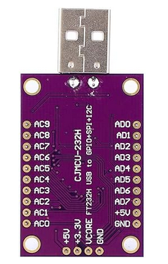
CJMCU-FT232H is a single channel USB 2.0 Hi-Speed (480Mb/s) to UART/FIFO IC. It has the capability of being configured in a variety of industry standard serial or parallel interfaces.
Feature:
- Single channel USB to serial / parallel ports with a variety of configurations.
- Entire USB protocol handled on the chip. No USB specific firmware programming required.
- USB 2.0 Hi-Speed (480Mbits/Second) and Full Speed (12Mbits/Second) compatible.
- Multi-Protocol Synchronous Serial Engine (MPSSE) to simplify synchronous serial protocol (USB to JTAG, I2C, SPI (MASTER) or bit-bang) design.
- UART transfer data rate up to 12Mbaud. (RS232 Data Rate limited by external level shifter).
- USB to asynchronous 245 FIFO mode for transfer data rate up to 8 Mbyte/Sec.
- USB to synchronous 245 parallel FIFO mode for transfers upto 40 Mbytes/Sec
- Supports a proprietary half duplex FT1248 interface with a configurable width, bi-directional data bus (1, 2, 4 or 8 bits wide).
- CPU-style FIFO interface mode simplifies CPU interface design.
- Fast serial interface option.
- FTDI's royalty-free Virtual Com Port (VCP) and Direct (D2XX) drivers eliminate the requirement for USB driver development in most cases.
- Adjustable receive buffer timeout.
D0 to D3 are used to configure I2C or SPI in MPSSE mode.
In addition to the serial protocol pins above, the MPSSE mode allows you to control other pins as general purpose digital inputs or outputs. These are great for controlling chip select, reset, or other lines on chips. You can even use the GPIO to read switches, blink LEDs, and more!
The pins which are controllable as GPIO in MPSSE mode are D4 to D7 and C0 to C7 ,for a total of 12 GPIO pins. These pins can be configured individually as digital inputs or outputs.
- 3,5 = I2C communication D0+D1,D2
- 13,15 = int4a int4b D4,D5
- 16,18 = int5a int5b D6,D7
- 22 = rpm sense C0
- 29,31 = charge / discharge counting C1,C2,C3,C4
So we have 7 pins needed (9 if using 2 Coulomb counters) to test the software GPIO control and 2 pins for I2C communication.
Adafruit Blinka: a CircuitPython Compatibility Library
Enter Adafruit Blinka. Blinka is a software library that emulates the parts of CircuitPython that control hardware. Blinka provides non-CircuitPython implementations for board, busio, digitalio,
and other native CircuitPython modules. You can then write Python code that looks like CircuitPython and uses CircuitPython libraries, without having CircuitPython underneath.
There are multiple ways to use Blinka:
- Linux based Single Board Computers, for example a Raspberry Pi
- Desktop Computers + specialized USB adapters
- Boards running MicroPython
Desktop Computers
On Windows, macOS, or Linux desktop or laptop ("host") computers, you can use special USB adapter boards that that provide hardware pins you can control. These boards include MCP221A and FT232H breakout boards, and Raspberry Pi Pico boards running the u2if software. These boards connect via regular USB to your host computer, and let you do GPIO, I2C, SPI, and other hardware operations.
The I2C interface connects to the base board and the base board connects to 2 input boards, 3 output boards, 1 ADC board, 1 fm radio, and 1 GPS modules.
To use I2C with the Adafruit Python GPIO library and the FT232H board you'll need to
setup your circuit in a special way. In particular you'll need to tie the D1 and D2 pins
together with a jumper wire. One of the pins will be read by the F232H as an input, and
the other pin will be used as an output. When tied together both these pins form the SDA
or data line for I2C. The D0 pin alone will be the SCL clock line for I2C.The second thing you'll need to do with your circuit is add explicit pull-up resistors from SDA & SCL on the FT232H up to 3.3 or 5 volts. This is necessary because the FT232H does not have pull-up resistors built in to these lines as it is a very general purpose chip. I recommend using 4.7 kilo-ohm resistors as these pull-ups.
To summarize, for using I2C you need to setup your hardware as follows:
- Connect FT232H D1 and D2 together with a jumper wire. This combined connection is the I2C SDA data line.
- Add a 4.7 kilo-ohm resistor from the I2C SDA data line (pins D1 and D2 above)up to FT232H 5V.
- Add a 4.7 kilo-ohm resistor from FT232H D0 up to FT232H 5V. This pin D0 is the I2C SCL clock line
Software screens were developed in Xbasic for testing screen functionality, converted to Python code using xbasic2Python. At this point, the USB GPIO adapter was plugged into to PC and wired to the Dash base board. Adafruit blinka library was added to the PC. Running the python code makes it possible to test all vehicle operations from the PC.
I found this to be the fastest way to do RAD (rapid application development). Once the code works perfectly on a PC, we copy the python code to the RPI computer and change the include library statement from “include blinka” to “include circuitpython” and adjust the GPIO reference pins to match connection of the base PCB to match the RPI pins. Save the new program to the RPI and make a back-up of it so we have it.
The digital dash control center can now be duplicated as many times as we want for as many EV car conversions as we want to do. During tests, a simple PWM inverter to a small AC motor is used but in the actual conversion we connect to the real Inverter and Motor.
Coding dilemma
We are doing a EV Truck application. The last thing we need to have is the inadvertent hiding or closing of the application while driving! To this end our main windows(s) must not have window frame, control frame, titlebar, or statusbar found in a normal GUI program. Mouse/Trackball/touchpad and keyboard are No-No's while driving so control is by dash switches, steering column controls, Brake pedal, accelerator, and E-Brake. These operator controls use the GPIO/I2C and are also select-able from the touchscreen of the dash display. xBasic, opengl, qt support frame-less/control-less/title=less windows but such might not be possible with gtk/glade.
Let's start with the basics:
We have physical user controls that are normally used in using a truck. We also want to marry these controls to function from software. Then we want to add our own bells and whistles like Radio, GPS, Hands free calling, Self testing and maybe more.
Ignition key Our Ignition key is replaced by a momentary switch that triggers the computer to on mode. Turning off the system is under computer control when the system is safe to shut down.
Other changes The
following other controls are handled differently than on the regular ICE type vehicle that uses idiot lights, and cables or sensors such as:
- Left-turn , Right turn and Hazard
These just pull a normal held high (5v) line to ground to signal the computer to tell it to show the turn signal as a flashing indicator instead of flashing a bulb on the instrument cluster.
The built in electronic flasher powers the front and rear lights
- Brake
Here again the computer illuminates brake when the brake is pressed. Normal brake function of the ICE operates the brake.
- E-Brake
Likewise here the ebrake is illuminated when the ebrake is on. It too functions without modification.
- Cruise
When cruise is active the display shows it is on. It shuts off if the brake is applied and normal accelerator action takes over.
- Fwd-Rev-Neutral-Park
The gear shift is not used. It is replaced with 2 momentary buttons FWD and REV. The switches don't work while the vehicle is in motion
- Wash - Wipe
Is one thing that doesn't get any computer involvement. It passes direct to the wash wipe control unit unchanged.
- Fan off - low - med - high
Will be handled by the computer. No user control buttons or switches will exist.
- Defrost - Vent
This also gets handled by the computer. No user controls exist.
- Heat level
As dose this
- A/C level
And this
So we now know which things need to be handled directly from our dash display. Everything else needs handling by the support routines and it's GPIO based automotive control circuits.
The EV is marriage between 5 systems
that function independently and also must work together. It gets this information from a series of special cards that connected with the automotive systems and the Drive Inverter.
There is one more note to make before we go into software development. In our final design, when the computer comes on to initialize, it monitors the one User interface we will have. This is a 12 button onscreen keypad or a RFID card reader. To enable driving software you must enter the multi-digit code or use the RFID card. There is one code for programming mode and one for run mode. 3 failed attempts shuts off the system. To turn the system back on you must repress the ignition start button.
Some structure changes
Having to reach the displays to make changes using touch screen technology, is fine for testing but in real driving it is poor design. So we have a marriage between onscreen touch and manual controls (signal lights, gear shift, hazard flash, Headlights, cruise and brakes). The dash display (instrument cluster) has desired cabin temp, Kph/Mph select, Headlights/running lights/hi-beam, Cruise, Back-up display and drive selection to be handled.
How the system does things in software is covered in a separate document
Chapter 11 Out with the Old in with the New
In this chapter we will go over the three areas of concern. The front canopy or engine compartment, the rear fuel tank area, and the interior dash and rear seat changes. We will be discussing and showing the removal of things that are no longer required. Then we will discuss and show the implementation of things needed to be added.
The canopy is the containing compartment for the engine, transmission, starter, water pump, air conditioning pump, steering pump, Air intake, battery, carburetor, exhaust manifold, and alternator that we will be removing. We will be keeping the Radiator, Fans, Windshield washer and reservoir, Radiator overflow, Electrical distribution, Power brake system, Power steering system, and from the axles to the front drive wheels. We are adding the electric motor, Power Drive inverter, And electric pumps for water, steering, air conditioning, and brake vacuum.
Engine Removal
I am not a mechanic so I will begin by saying there are so many changes that have been made since I worked on cars and trucks years ago. The engine and everything associated wont be reused with the following exceptions. Don’t disconnect the AC lines just remove from the engine and set aside as we can add an electric motor and belt to run the AC. Keep the power steering pump for similar re-purpose. The ficm, icm, EGR, Exhaust pipes, Catalytic, Muffler, Tail pipe are no longer needed.
From a video on the topic of removing the engine from a chev 2500 Silverado, we start with the new owner of this truck bought as salvage. The engine was blown and the previous owner had already removed and discarded everything above the intake manifold. The new owner said he was very happy with this because it eliminated hours of tedious work. An engine removal job is complicated due to stuff in the way and hard to reach clips, bolts, and screws.


After draining all fluids he raced around disconnecting stuff from the top and finally removed the intake manifold. From the clock on the wall it took him 3 hours.


Another 4.5 hours saw him removing the starter, undoing torque converter bolts and moving the engine around to get at hard to reach stuff.


Next he started raising the motor, careful not to bang it into anything. He had to deflate the tires to finally clear the vehicle.


600 lbs of useless iron filled with 8 explosive chanbers, pistons, pushrods, camshafts, is fanally out of the vehicle. How ever did we make it through the last 100 years


The engine compartment is basically empty. We can remove the transmission, drive shaft, rest of the exhaust system and turn this space into a storage space.
The drive shaft will be shortened, a small gear box will go between the electric motor and drive shaft all located back by the differential.
Transmission removal
This video taken from the perspective of removing a transmission with motor still in place.


First off I gather he said exhaust will be in the way so remove it. Remember to disconnect the battery before touching the transmission.


After the Y pipe for exhaust is removed, locate and remove the 3 plugs on the passenger side of the vehicle


The start-Neutral switch must be removed next and unseated from the bracket.


Remove the drive shaft from the rear differential.


Before you take the shaft end from the transmission place a container to collect the transmission fluid.


This vehicle has seen plenty of oil leaks. The engine removal video didn't show this step that he had to do to get the motor out. 3 bolts hold the starter into place. The engine must be manually turned to access 3 torque converter bolts


Loosen two bell housing bolts and transmission cross support frame bolts.


Support the transmission and work the vaccum lines off from the top


Work your way around undoing the bell housing bolts leaving the botom two for last. two at the top will have bracket and ground straps on them that must be removed.
 I am so glad nothing like this engine or transmission is going back into this unit. Here we show what it will look like if the engine was not removed


Motor length goes down from 4 ft to 14 inches! Motor width is 12 instead of about 3 ft x 2 ft.
To give an idea of how a transmission might be altered. We need to change the multiple gear ratios and valve body and torque converter as follows. Delete torque converter. Main shaft will no longer have hydraulic activated gears and instead will have a single gear that does forward and reverse without need for clutches.
In the above fwd example the Transaxle once removed is modified to remove the torque converter valve body and gears. Instead of clutch / gear combinations we seek a fixed gear which drives in both directions because the motor actually rotates both directions.
Fuel Port removal


We can reuse the fuel port on most vehicles and add our electric charge outlet. Remove 3 screws to remove the old fuel filler add our AC shore charge port here. It is basically a flat plate with a plug socket in it and a micro switch designed to trigger when the shore power cable is inserted.
Fuel tank removal
Step one is to drain the fuel tank as much as possible. A siphon pump does a good job.


The fuel tank has a plastic cover over it. It has a mount in the front corner.


At the back and other side are clips to hold it in place.


Once the clips are released, it may be taken out of the way.

Fuel filler line and vent lines go up over the frame with line clips that can only be accessed by disconnecting the filler at the fuel door. So remove the gas cap and normally you would plug the fill line so nothing gets into the tank, but since the tank is being eliminated you can just remove 3 screws holding the filler in place.
With the filler removed you can eliminate the line to the tank.


Disconnect the vapor canister lower line and the upper fuel line and install straps to support the tank and and stand to lower the tank once mounts have been removed.


I know the pictures are terrible. As you can see there is plenty of line to make disconnection easier.
We wont be needing the fuel tank, fuel pump in the tank, vapor canister, vent line, and fuel lines. .

And finally lower the tank down, remove and discard. We are removing the tank as this re-leaves us of a great deal of weight.
Dash instrument cluster removal
There are so many models of every imaginable configuration so here I will explain how the steps go for just one vehicle.


For the silverado 2500, dash removal starts with lowering the steering wheel down. Start the vehicle and move the gear shift to the lowest point and shut off the ignition. Then gently pry up the dash trim starting top right corner.


Now move from the right across the top to the left releasing the trim from the clips. Fold down a bit to release the lower clips and lift it away.


You now have a clear shot to remove the Instrument cluster, radio, and heating control. Four screw each are securing the instrument cluster, and Radio/heating cluster.


After removing the screws the unit can be tilted out to disconnect it


In a conversion, The Universal EV dash display 7" type will likely fit right in the space with a fancy wood grain panel shaped to the instrument cluster form.
 The dashboard wiring likely will serve no purpose.
Canopy systems
The Canopy systems are those systems that reside under the front canopy hood. They basically are the replacement of key systems lost by removing the ICE engine. We will need:
- a Power steering pump (12v)
- a Brake vacuum pump (12v)
- a Radiator Fan (12v)
- 2 Rad flow valves (12v)
- A/C 12v compressor
- 2 Temp sensors (1 for cabin , 1 for Motor/inverter)
- and water pump (12v)
In addition, we are retaining of course the:
- Headlights
- Signals
- Wiper motor, Washer pump
- Horn
- Washer resavior
- Radiator surge tank
and need to have a full hvac plan for the cabin cockpit.
Installing the New systems
My proto-type dash unit is 10”x8”x6” with a 10” display on it’s face. While mine used descrete components a production model would use smt’s to reduce size to 10”x8”x4”. Other possibilities for the Universal dash would be a 7” display 5.5”x6”x4”, or a 4.3” display 3”x4”x4”
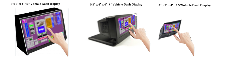 The units are self contained such that they can be removed and fully tested with a PC or left in place and tested in the vehicle. There are no cryptic numeric codes like the ICE vehicles have. All inputs and outputs can be tested on screen. Each unit contains 1 computer, 2 input modules, 3 output modules, 1 ADC module, 1 radio, 1 amplifier, 1 gps, 1 dashcam, 1 mother board. Depending on the size of the
instrument cluster of the vehicle will determine which display would be best. You should want to limit modifications to the dash as much as possible. The existing radio, heating control and info center will likely not be needed.
The units are self contained such that they can be removed and fully tested with a PC or left in place and tested in the vehicle. There are no cryptic numeric codes like the ICE vehicles have. All inputs and outputs can be tested on screen. Each unit contains 1 computer, 2 input modules, 3 output modules, 1 ADC module, 1 radio, 1 amplifier, 1 gps, 1 dashcam, 1 mother board. Depending on the size of the
instrument cluster of the vehicle will determine which display would be best. You should want to limit modifications to the dash as much as possible. The existing radio, heating control and info center will likely not be needed.
Chapter 12 will cover the battery construct and installation. Chapter 13 will cover the traction inverter and traction motor along with the transmission modification Chapter 14 covers the solar charging, and the charging system. So that leaves us with the HVAC system for heating and cooling. Doing the canopy controller, and doing up the new pumps for brake vacuum,
and power steering.
New systems in the canopy
We can leave the lighting and windshield wash/wipe system alone. First off remove the Battery of the lead acid type. The fuse and distribution block will likely be redone to better suit our needs. Currently the lights are all 12v incandescent which draw a huge amount of power. In the old ICE system the alternator supplied heating, lights, cooling, battery recharge and the engine timing spark/injector spark. And you may have noticed that at an idle lights would dim especially if you were using defrosters. We can certainly keep doing things this way but if we change all lights to LED strings, the marker lights change from 4 x 6A bulbs to 1 series string of 40 LEDs with 10 at each corner of the vehicle with a draw of .02A. The Turn signals go from 2x 6A bulbs per side to a 40 LED string with 20 at the front and 20 at the back per side and again draw 0.02A per side. Brakes, License and Reverse lights also follow this pattern. Net result we have better lighting of these features and instead of 66A if all are on at once to just 0.22A. The Fog lights and Headlights will have to stay as is and we just need to have a small relay board to convert the digital control from the computer into high power 12v for these bulbs.
Then we are adding these 3 systems:
Them's the Brakes
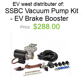
The Easiest way to get brakes working on an EV conversion is to replicate the Vacuum pressure that used to be supplied by the ICE motor. While it is true that regenerative breaking will slow you and stop you over time, it can even prolong the life of your seldom used padded brakes, but you still need power assisted hydraulic brakes for fast stops, emergency stops, traffic navigation, and holding you still at lights and on hills.
|
New Steering pump
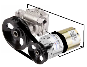
The next thing you need is power steering after deleting the ICE motor which had your power steering pump. Hopefully you saved the pump off the motor so you can make a EV equivalent. You will need a pulley, a belt, and a 12V motor to drive the pump pulley.
|
Electric Water pump
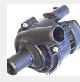
There are four places where water circulation is important. These are of coarse to heat or cool components and to heat or cool you. So, in the grand scheme of things, If we use a radiator and fan like we
had in the ICE vehicle, and pass water glycol mix through an electric water pump (replacement for ICE engine), we can supply heat to the cabin for us, and cooling and heating to the batteries, Inverter, and Electric drive.
|
|
Working on HVAC
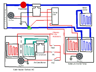 For heating and cooling, we will pass the Radiator Water outlet line to a 12v pump and 2 electric valves. If the Motor, Inverters, and Batteries are too hot, the associated valve opens and the fan engages
to cycle the solution through the Radiator for cooling. In the cabin, I guess I could have routed a take off from the radiator to pass through the inside heating vents but chose instead to use a two speed fan and a choice of heat on through ceramic heater, or AC on through a 12v compressor of refrigerant.
For heating and cooling, we will pass the Radiator Water outlet line to a 12v pump and 2 electric valves. If the Motor, Inverters, and Batteries are too hot, the associated valve opens and the fan engages
to cycle the solution through the Radiator for cooling. In the cabin, I guess I could have routed a take off from the radiator to pass through the inside heating vents but chose instead to use a two speed fan and a choice of heat on through ceramic heater, or AC on through a 12v compressor of refrigerant.
As seen here, While the motor, Inverter, batteries are below 50 degrees F, the radiator fan is off, the bypass value is bypassing the radiator and the coolant pump is off. Once temps rise to above 50 degrees F the pump comes on and when temps climb above 170 degree F the valve opens to redirect full coolant flow through the radiator and the fan engages.
It's important that the Batteries and Inverter remain in the operational range during Driving and charging so if they are too cold an auxiliary ceramic heater and fan comes on to raise the temperature, If too hot the fan comes on to cool them.
Out with the old
The ICE engine tended to run at about 210 to 215 degrees F and had a thermostat to keep temps close to that. Inside we commuters would scramble to try and keep things for us at 72 degrees F. So the thermostat would stay closed until the temp of the engine had raised to above the thermostat temp then it would open and the fan would force air through the radiator to cool the liquid circulating through the coolant system. The engine was happy as long as the coolant kept it at a constant temp. Inside our windshield was frosted, and our teeth chattered. Eventually there would be heat coming through the ventilation enough to clear the windows and start to warm us up. In Summer, a different story
happens. The engine starts out already warm enough and gets concerned about how not to get too hot so the thermostat opens earlier to
circulate and keeps things cool for the motor. Inside we call for the air conditioner to do it's part. A valve opens in the air conditioner to allow refrigerant to circulate and a blower passes the cooled air into the cabin.
In with the new
The electric Motor and Inverter likes to maintain a steady 150 to 180 degrees F. So in winter or cold weather, you want to keep the thermostat closed and circulation to a minimum both inside and through the motor and batteries. You may even want to help the motor and inverter sustain minimum of 50 degrees F by heating the solution. Then as the coolant raises to above 170/180, kick in the thermostat (open it) to let fan draw air and cool the coolant. The coolant then circulates through the batteries, Inverter, and Motor. For the cabin, you want positive hot air flow over the
windshield to defrost it and heat the interior by tapping off heat from the motor coolant system, and electric ceramic heat to assist, In summer, you want to open a valve to a refrigerant system to circulate past a blower that sends cooler air into the cabin.
Power center
For your truck I anticipate a similar lack of planning that was found in the motor home and every vehicle I have owned. The auto industry is well known for making
cables (harnesses) for a huge number of features covering many models of vehicle and several styles in each model. As a result, in any
model-style series you will find many cables terminated with a spade lug going nowhere. None of the cables are usually labeled except maybe at the fuse block or control module.
The motor home had 3 fuse blocks, a wash/wiper module, a ficm (fuel
injector control module), an ICM (ignition control module), an ECM (emission control module), a PCM main control box, an instrument
cluster and roughly 400 wires that went from various modules but went nowhere else. You will find much the same but, and there is always a
but, being that it is being made an EV-Truck, we can delete the ficm, ICM, ECM, PCM control box, instrument cluster, and all non-essential
wires with no need to give them any thought. This will also include oil sensors, timing sensors, temp sensors, emission sensors as well.
Your new Dash controller will have connectors for: 1 mirror control, 1 window control, 2 for seat-belt/door/bin sense, 2 for automotive output control, 2 for signal, brakes, Cruise, 1 for
charge, 1 for power, 2 speaker wires and 1 for canopy control.
EV Battery and motors from wrecks


Here we have a battery pack from a Toyota Prius. The box has an upper and lower half glued together. Because it had no venting it really smelled bad once opened and needed to sit for a few days to let it air out. Even though it is one huge pack it is split into 5 sections.The pack actually made up the floor of the car. The high end was under the rear seat.


There is a mase of high tension wires interconnecting the sections with the main power connection in orange at the front. The pack is 200v at 500A and being open is very dangerous. With rubber high voltage gloves on you remove the high tension wires.


With all wires removed the sections can be lifted out and are safe. Testing the pack sections revieled 4 of 5 were still at 97% and the 5th (big long one) was at 80%. Each section is sealed so to make use of this pack each must be broken open, deconstructed, and reconstructed. A new container fitting the new vehicle will hold the reconstructed pack.
Now for the 144V AC motor
Motors are larger as the AC voltage reduces. Having a 200v pack means you can't run a 230V AC motor which is half the size of this one.


As the story goes, this guy obtained a motor inverter and trans axle assembly from Toyota prius to fit into his car that no longer had a engine or transaxle. In image 2 he dry fit the unit in and took some measurements.


Removed the motor, made some brackets for the motor and transaxle support and put the motor back in place.


Attached the brackets and the motor is installed. connected up the cv axles and this conversion is ready for the rest of the EV conversion.
 Total time start finish including making brackets under 2.5 hours. No bashed knuckles, cursing, 1000's of hard to reach spots or grease grime and oil coated parts like an ICE removal had.
Chapter 12 EV Battery Bank system
Choice of cell types
Batteries lie as the source of energy to power the EV. The type and configuration of the Batteries determine the potential of project design. Below are the specs for the four common lithium cell types. While all four can be combined to make the Banks or packs, the cell size and availability are the determining factors to project success.
In this chapter the term cell or battery refers to the individual cells like items 1,2 and 4. Gcells will refer to the 3rd type below as a
Gcell that is really a group of type 1,2, or 4 arranged into a single larger device. A Bank is a group of Gcells and a Pack is a group of Banks.
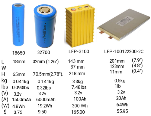
The 18650 was the original cell of choice for EV at 18mm x 65mm providing 800 to 1500mah. $5 to $12
The 21750 is the new choice at 21mm x 75mm with 5000mah $16
The 32750 is my preference 32mm x 75mm at 6000mah. $10 is the cheapest cost of the 3 and although it is bigger and heavier, when your talking about 1000’s of cells to make a pack it is significant.
Consider this:
To make a 384v 144A bank with 2 banks to a pack we need 120 rows in series by 144/cell Amps in parallel per bank with banks then placed in parallel.
- 18650 cells = 2 x (120 x 96) = 23,040 cells $276,480 2142 lbs
- 21750 cells = 2 x (120 x 29) = 6912 cells $110,592 691 lbs
- 32750 cells = 2 x (120 x 24) = 5760 cells $57,600 1843 lbs
Factors to consider in converting a vehicle into an EV is really weight vs cost vs range in miles. Gas tank sizes vary so we will just use 20gal so fuel weight is 120 lbs + tank at 18 lbs, engine and transmission 400 to 700 lbs so we will use 550 lbs, exhaust system 80 lbs, lead acid battery 85 lbs. So when we convert a vehicle we are reducing curb weight by 863 lbs. We further remove about 10 lbs of dash equipment like instrument cluster, & radio. Then we add back the motor, inverter, and digital control center 180 lbs. So we are 683 lbs lighter in curb weight at this point. If we use 2) above we are only 8 lbs heavier by adding battery pack but our conversion cost climb by $2000 plus $110,000 plus labor. Using 3) above we are 988
lbs heavier but conversion costs are $59,600 plus labor.
Curb weight does not include driver, passengers, cargo on cars and trucks so we can’t use curb weight to define range. On a Truck as outlined here, curb weight was 4920 lbs and the GVWR is listed at 6800 lbs. So this tells us 1980 lbs is recommended weight of people and contents. 4 x 220 lb adults leaves 1100 lbs of cargo using 2) above, and we are 140 lbs for cargo, using 3) above. Miles of travel is = Kw/(GVWR/10,000) with Kw = V x A so with 384V x 288A = 110.592Kw. Total distance in miles = 110.6/0.443 = 495
miles between charges. The average person travels under 12,000 miles a year according to the insurance bureau of Canada. That is 32.8 miles per day so you could travel for 15 days between charges but being that you can plug in to 120v AC each day, the 19.2A used for the day would take a mere 4 hours to recharge. So for daily commuters in a Car we could reduce Pack Amps from 288 to 80 with recharge every 4 days.
To make a 384v 40A bank with 2 banks to a pack we need 120 rows in series by 40/cell Amps in parallel per bank with banks then placed in parallel.
- 21750 cells = 2 x (120 x 8) = 1920 cells $30,720 192 lbs
- 32750 cells = 2 x (120 x 7) = 1680 cells $16,800 537 lbs
What this has done is reduced # of cells, reduced costs and reduced the weight. The GVWR was 4430 lbs before conversion and using 2) above became 4438 after but now has 593 lbs available for cargo. The same for 3) above where we were 28 lbs over weight without people and contents, is now has 228 lbs available for cargo while carrying 4 adults.
Our proposed battery packs for Cars and suv’s for commuters would be 2 banks of 8 Gcells, Each Gcell would be 15 series rows x 7 cells in parallel. Each Gcell would be 48v @ 42Ah and Gcell weight would be about 34 lbs and cost $1050.00 . Range between charges would be 70 miles with 4 hours charge time per day if driven 32 miles a day. Charging costs $2.39 a day compared to ICE at $6.07 a day if 30mpg. Savings over 15 years $20,148 - $16,800 for new batteries = $3,348.00 for vacation! (does not include interest on savings).
People needing higher ranges could pair up packs in parallel such that banks become 2 banks of 2 bank packs (4 banks wired with 2 connected together as one).
- 32750 cells = 4 x (120 x 7) = 3360 cells $33,600 1074 lbs range 140 miles
- 32750 cells = 6 x (120 x 7) = 5040 cells $50,400 1611 lbs range 210 miles
The problem of doing this is that the weight is too much for small cars and mini-vans. MIdsize cars and light trucks might be able to handle 1) above, but only full size cars and ¾ ton Trucks or larger can do 2) above.
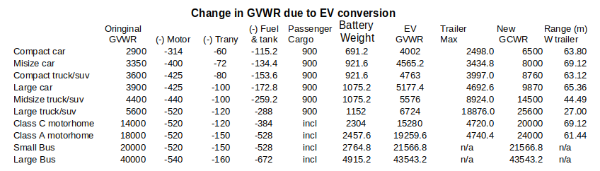 Remember that the auto industry wrongly specifies GVWR by curb weight which excludes passengers and cargo. The Car curb weight was 3460 but had a GVWR of 4430. The GCWR of the Car allowed for a trailer of 3000 lbs so technically, because it’s GCWR listed at 7400 lbs we could attach a 3000 lb trailer with capacity for 2100 lbs and use 537 lbs of that to add additional battery banks. Thusly, bank-A now has the onboard bank and the satellite bank-A in parallel and doubles Amps to 80A. Bank-B now does the same and our range almost doubles during run. Our GCWR now comes into play. With GVWR of 4430 + 3000 for the trailer we are now at 7430 GCWR we have now got 61.44Kw so 61.44/0.743 = 82 miles instead of 70 miles if the trailer is full. We gained more range by adding battery banks but lost range because cargo space increased by 1600 lbs or more. If the trailer costs $1,400 and battery banks cost $16,000 our range increase of 10 miles cost us $17,400. On the other hand, if the trailer only has the battery banks, GCWR is 5867 and 61.44/o.5837 = 104.72 miles.
Battery Pack health
Cells decline and fail at different rates. As cells in use go through life they start taking less charge as they age. In a ‘one pack does all>’
this can mean that if rate of decline results in say 10% of original distance the answer is to replace the whole pack for $16,800 for example. But because we are using Banks, If only 1 bank has declined rapidly, we can replace the bank $8,400. Our banks are 8 Gcells that are individually replaceable so narrowing it down to a Gcell now results in $1050 as cost of repair. The user can now replace their own battery Gcells just like we do when our lead acid wet cells need replacing. An $85 wet cell is 80 lbs and sits on store shelves. With standardization we can have stores stock our 34 lb Lithium cells on the shelves for $1050 each. Environmentally, we are moving away from harmful lead acid in favor of recyclable lithium ion.
Just like with lead acid where we turn in the battery for core charge so it can be rebuilt, the gcells can be rebuilt. Open the Gcell and extract the micro-cells (4 x 12v micro-cells) = 1 x 48v Gcell. Disassemble the micro-cells (tapping strips go for cycling), cells in good shape maybe reused, poor and bad cells go to final recovery. Gcells get rebuilt from new cells and new tapping wire. Reusable cells may go into games, laptops, flashlites etc where shorter lifespan is not so critical.
Because we have almost all cars, truck, suv’s using 12v systems and the 4 x 12v micro-cells make our Mini-packs (Gcells) we need to bring the 12v junction out as a 3rd terminal on each Gcell so it may be used in the first position of each bank.
Resale and recovery value
People have two options maybe more when it comes to vehicle recovery value. The Motor, Inverter, Electronics, and Battery Pack are totally salvageable from a wreck or worn out car. It is unlikely that the insurance will offer you much. That 2000 malibu which the insurance writes off at $2200 as a gas vehicle will likely still be $2200 as an EV even though you have $17,000 invested and only used up 1 of 15 years life.
The true value is $15,866 + $1000 for value of body. A better choice is to buy it back as salvage $50 remove the Motor, Inverter, electronics, and Battery Banks for reuse in your next vehicle or resell them and scrap the rest. On the other hand you want a new or different car. The auto lots are not your friend. They understand ICE, that looses $2000 the minute
you leave the lot. An MRSP of 30,000 = 30,000 – mileage/10 – 2000 so if car is over 280,000 miles it has trade value of 0. Another vehicle with same MRSP with 80,000 miles might be worth $20,000 trade-in if not too old and in great condition. This is because ICE has lifespan of 300,000 miles but an EV has lifespan of 1,000,000 miles on EV part and 300,000 miles on the body. If you decide to sell privately you will need to show records proving how long the batteries were in use which includes odometer at battery change and current odometer.
The whole industry is in for a shake-up if all vehicles have to be electric by 2040. 5 million vehicles in north America will have a value of 0 in 2040 unless they are electric. A look at the ford lightning F150 vs F150 gas reveals, $51,000 vs $38,000 ($9,000 is value of ICE parts) so $32,000 is their claim to EV over the $29,000 chassis. The specs aside from some bells and whistles claim 10,000 lb towing on the EV vs 14,000 towing on the ICE which is 1100 lbs more than my research showed. Range was stated at 230 miles to 300 miles vs 450 to 550 miles but they leave off the Kw of power so I have a hard time calculating true Battery Pack specs. $32,000 suggest a 4 bank equivalent = 160A and presuming they are using 384v standard that says 61.44Kw, they don’t give the GVWR or GCWR but if we use my figures 5580 lbs that says 61.44/0.558 = 110 miles not 230 to 300. To attain their figures we need 350A of battery. 8400 cells @5A 21700 cells at $3.81 each which is possible if buying in bulk like an auto maker does. For our concept we would have 35 cells in parallel x 15 cells in series per Gcell, and 8 Gcells in series per bank with two banks. While I am doing this from DIY standpoint I have to go with consumer costs of $16 per 21700 cells but auto makers and a conversion shop could buy cells in bulk as can battery Gcell makers and source cells at about $4 per 21700 cell to ultimately reduce conversion costs, and weight, and bank sizes.
- 21700 at DIY consumer price $16 ea, $1680 per Gcell 9.45 lbs $26680 per pack total wt 151 lbs
Gcell size 5.5”x5.5”x6”
- 21700 at wholesale price $4 ea, $420 per Gcell 9.45 lbs $6720 per pack total pack wt 151 lbs
- 32700 at DIY consumer price $10 ea., $1080 per Gcell 34 lbs $17280 per pack total wt 544 lbs
Gcell size 10”x10”x6”
- 32700 at wholesale price $2.50 ea. $262 per Gcell 34 lbs $4200 per pack total wt 544 lbs.
To enclose such a Gcell you want it to be safe for operators, ventilated, short proof (conductivity safe),and reasonably light. In the above scenario, in each case we get 40 to 42A Gcells which are smaller than a standard 12v lead acid battery and far lighter with no harmful acid in it. By the time you add $3500 in motor, Inverter, and Dash computer and charger-switcher a vehicle conversion shop can likely convert a car for $10,220 + Labor. No matter how you slice it, 16x 6” cubes for battery or 16x 10” cubes brings great promise and cost effectiveness to converting regular vehicles to EV.
The safest Packs are those with:
- Plastic or fiberglass structure so
that people can be kept away from extreme energy supply..
- No Exposed High voltage or high current connections
Gcells would have 3 screw terminals [+48v.+12v, Neg) So not that much different than a lead acid with 2
terminals (+12v, Neg). The Gcell is 42Ah and the lead-acid is 65 to 85Ah.
For very practical reasons, each bank needs temperature monitoring and control, Voltage Balancing, Charge balancing, State of Charge, State of health, and functional control. BMS is the go to method of protecting the battery banks. It isn't as straight forward as they lead you to believe. Yes the BMS protects the Battery from over voltage, over current, over temp during charging and shuts the whole process down if it encounters any such condition. It can jump in if there is a short circuit so as not to damage the battery. Under live operation, BMS is both good and bad. It tries to balance all batteries to be at the same voltage either passively or actively. But voltage does not have much to do with it compared to SOC, SOH When one cell reaches full charge BMS stops charging all cells it is in control of.
Making custom Gcells from cells
The cells that are used to make up Battery packs come in 3 basic styles and a multitude of Amperages and qualities. China produces the least expensive but also the poorest quality cells around.
Our target will be high quality 32700 liFepo4 cells rated for 6A per cell.
Gcells are commonly made of blocks of 2x5, 3x5, 4x5, 5x5 or combinations of them. If you need 12v then you need 4 series cell-blocks. For 24v you would have 8 series cell-blocks and for 48v you would have 15 series cell-blocks. Note cells are 3.2v and a 12v battery is generally a 12.6v to 12.8v battery. By the time you make it to 48v, 16 blocks would make 52v not 48v. But 15 cells works out to 48v precisely.
Each time you combine another cell in parallel the current goes up by the cells current value. Always keep cells with-in each Gcell of the same type and rating. A 48v 200Ah Gcell Battery would take 15 series cells x 34cells at 6Ah in parallel.
This design seems more feasible with 4 micro-cell blocks in an 10” x 10” x 6”. Add a 16 pin connector with pins 1 to 15 going to each (-) and pin 16 going to +48v and we have BMS ability.
1 bank would be 10” x 10” x 48”
So it's time to look at the equipment you will most probably need to make battery packs.
- Multi meter : Volts / Amps / Ohms measurements
- Soldering Iron 35watt or better.
- Spot Welder : to interconnect batteries.
- Glue gun : secure Batteries into enclosures
- Heat gun : wrap connections to make them safe.
- 3DPrinter : make custom enclosures.
And the supplies you will need to make battery Packs
- nickel strips : interconnect cells.
- plastic 1x2, 1x3, 1x4, 1x5 battery forms
- weld rods
- 1.75mm 3d filament (multiple colors avail.) 3d print enclosures.
- Gimp / FreeCad / 3D print software.
Until you have all the equipment in place there is little need to start on the project.
The Spot welder is the first and most important thing needed to make battery packs. Heat from soldering irons can damage the batteries fast so avoid doing that!
Make a simple battery pack
 You have some up front decisions to make about the pack you are about to make.
- Will the pack block be Parallel cells only or Series/Parallel?
Parallel only pack blocks all the batteries of all rows have the Negative all connected to each other and all the positives likewise. Current is sum of all cells
additively.
Series / Parallel pack Blocks each row connect cells in parallel but columns are connected in series.
- Will the pack have internal BMS?
With BMS each series cell is monitored and balanced. End user does not get any visual report of cell conditions.
- Will the pack have internal Cell logging with alarm.
Cell logging provides a voltage readout
display that cycles through each of the connected series packs. The alarm goes off if a pack drops below minimum set voltage.
- Will the cells have temperature monitoring built-in
- Will the packs be centrally recharged or individually recharged.
- Will there be active coulomb counting for strict capacity measurement.
<
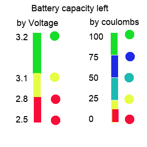 < Capacity methods
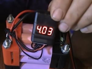 Cell loggers check voltages and Coulomb counters check Amps
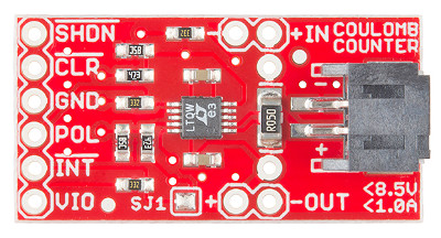
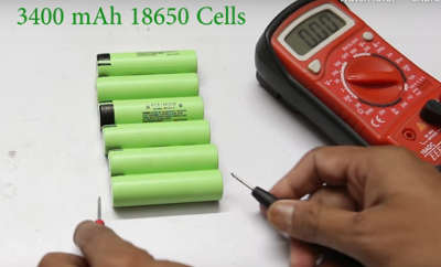 Fully charge all batteries and let them rest for a least 5 minutes then measure them so that you make sure each row has identical voltage. Ideally you also need to chart internal resistance and here is how.
Internal resistance
Make a spreadsheet for your cells. For each cell measure the open voltage and record it. Pick a resistor and record it's read value. Put the resistor across the cell ends and measure the voltage across the known resistance. Record this next to the battery it refers to. V=IR so I=V/R. With the now known voltage across the resistor and known resistance we can calculate I. And knowing I, we can use (Vopen -Vload) / I = Rinternal. So for each cell record the Rinternal. Any cell with a high internal resistance will not work well in a Gcell. Are you sure you can trust a Gcell was tested properly and balanced properly before you got it?
Before you begin making the packs it is important to closely measure the voltage of each cell and group them such that all cells per Gcell read the same. All cells in a parallel bank will gravitate towards the weakest cell's voltage. This makes it difficult for the BMS to level out the batteries consistently.
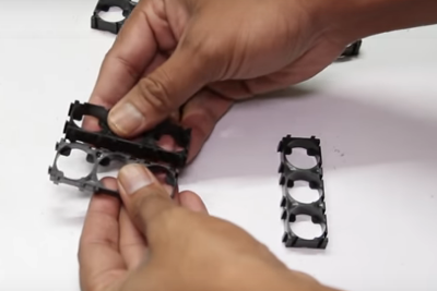
 Build your forms to accommodate the Gcell arrangement. In our case for a 10” x 10” x 6” Gcell we can go with 8 cells x 7 cells x 2 forms and 7 cells x 7 cells x 2 forms. For 32700 cells the forms are 1x2 or 1x3. If we connect 2) 1x3 and 1) 1x2 end to end and do 7 rows of that we have 1 form made. We repeat form 2, then connect 2) 1x2 and 1) 1x3 end to end and 7 rows of that we have form 3 made and repeat for form 4. Observe polarities ! All 7 columns in a row must be all (+) down or all (+) up. Row 1,3, 6, 8 should be (-) down, with Row 2, 4, 5, 7 being (+) down.
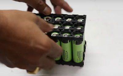
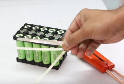 Once all cells are in place secure the top frame. We now need to cut tapping strips in Preparation to wire the cells. Remember these cells are fully charged.

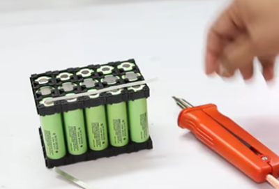 We will connect all (+) in each row together (Parallel) and connect short Tapping strips between (+) and next rows (-). Row 1 (-) also gets all 7 columns connected. Each (-) row gets a Tapping strip with a wire on for the BMS and row 1 (-) get heavy wire to (-) terminal, Row 5 (-) gets heavy wire to (+12v), Row 8 (+) goes heavy wire to Row 9 (-), and row 15 (+) goes heavy wire to +48v
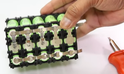 This example shows (+) row with all columns connected in parallel and in series with next row. In this example row 1 (-) is (- pole), row 1 (+) has (+3.2v) . Row 2 (+) connect all (+) together and all (+) wire to row 3(-). And row 3 (+) all connect together and a wire to (+9.6v) as this is a 9.6v Gcell with a 3,2v tap.
To split or not to split
When it comes to high voltage battery there becomes a very difficult problem. We have 15 cells in series and 7 cells in parallel to make 48v. The BMS needs to monitor each series cell row to balance them. Then we take these 48v gcell blocks and connect them in series to create the 384v bank and then connect two identical banks to make the 384v pack. Our most economical charge source is 57v such that we can charge direct from solar and / or convert 120v AC to 57v DC and charge from a shore line. Converting 57v to 420v DC to charge a 384v DC pack is extremely expensive and quite loss prone. Manually disconnecting 48v blocks so they can be charged individually is time consuming and potentially hazardous. So I needed another approach. the 48v blocks are in series during vehicle run operation but, and there is always a but, what if we electronically convert the series blocks into parallel to charge them.
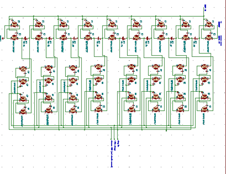 High power mosfets like the irf540 N-channel can handle the high voltage and current in the arrangement but, and there is always a but, it take 2 mosfets to replicate a switchover due to properties of the diode body of the mosfet. Two mosfets are used between each battery block and between the first and last battery block and the +384v and traction ground. Then there comes connecting the (+) and (-) of each battery block to the charger. The mosfets use 4 to switch the cells into parallel. This description is for only one bank. We need to do this on both banks. So we have 48 mosfets per bank. Ouch! thats 96 $1.36 Mosfets = $130.56 to do the switching. To save us from a PCB size nightmare and wiring nightmare, we can connect 6 Mosfets to each 48v block along with the BMS so that now we have 16 wires confined
with-in each block for BMS and a simple (+) and (-) (En) (Chrge) (chrg+) (chrg-) passing from block to block. Special note:During RUN system ground = Run ground and charge ground is disconnected. During charge, system ground = first 48v block ground, Run ground is disconnected and charge ground connects to all block (-).
High power mosfets like the irf540 N-channel can handle the high voltage and current in the arrangement but, and there is always a but, it take 2 mosfets to replicate a switchover due to properties of the diode body of the mosfet. Two mosfets are used between each battery block and between the first and last battery block and the +384v and traction ground. Then there comes connecting the (+) and (-) of each battery block to the charger. The mosfets use 4 to switch the cells into parallel. This description is for only one bank. We need to do this on both banks. So we have 48 mosfets per bank. Ouch! thats 96 $1.36 Mosfets = $130.56 to do the switching. To save us from a PCB size nightmare and wiring nightmare, we can connect 6 Mosfets to each 48v block along with the BMS so that now we have 16 wires confined
with-in each block for BMS and a simple (+) and (-) (En) (Chrge) (chrg+) (chrg-) passing from block to block. Special note:During RUN system ground = Run ground and charge ground is disconnected. During charge, system ground = first 48v block ground, Run ground is disconnected and charge ground connects to all block (-).
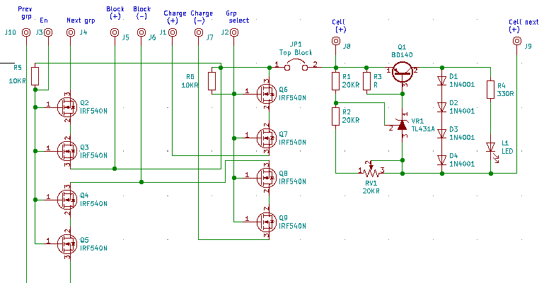 Ignoring the right hand side of the schematic, (BMS part), we have the new 48v switching circuit that will be at each 48v block. Prev-grp applies only to the first 48v group and it connects to RUN GND. Q4 and Q5 are used to connect or disconnect RUN GND to Block (-). On allother 48v blocks Prev-grp Q4 and Q5 aren't used. En chooses connect or disconnect blocks. Block (+) and (-) connect across the 48v block terminals. Chrg (+) (-) are the charging source and they connect across the block terminals when grp-sel is active. Block (-) connects to Next-grp of the previous block.
So back at the computer, it is told to charge the cells by the operator (you). It sees it has 94,000 ticks (5958 ticks per amp) or 15A left. It knows the pack is 120A or 714,960 ticks when full. So it selects Charge Enable and unselects Drive Enable. At the battery pack, all Mosfets between groups of 48v stop conducting. All Group gcells connect to charger in parallel on both banks. Each time .00017A goes into the battery group, 1 tick occurs and so the computer adds 1 to the ticks. When the ticks add up to 714960, the computer unselects Charge Enable and selects Drive Enable. Back at the batteries, all gcells return to series and are disconnected from the charger. When all is done the computer looks to see if the operator selected shutdown when charged or not. If shutdown then turn off everything otherwise switch to main screen and wait.
Since the topic of high currents of the battery packs has been mentioned often, we need to address it. Lets say our Battery source is 384v @ 168A like we have. From the research on handling high voltage and current they make a very valid point. It is highly dangerous to have a power source over 100A continuous and in many jurisdictions it is even criminal. Most people own a car of some sort. It has a battery that is usually 65Ah or higher and this battery also has another rating 800 to 1500 CCA which refers to cold cranking Amps. Since the CCA is used only during the starting, it is deemed non-continuous and safe. Our 168A pack follows the same guideline. During the 1/120th of a second at motor start it draws 250A but then draws beteen 0 and 10A depending on load and speed. It's kinda like if we directed all water from Niagra falls into your shower at home. Use of the whole all at once would drown you but using a tricle is enough and great. The DIY sites abound and talk of 600A to 1000A systems. They are talking about the current used over the whole range to travel not the typical current draw at a moment in time. If it were over a moment in time the maximum range would be maybe 2 miles. It is over the whole range. so if you have 56 mile range, and it uses 560A to do that range, you are using 10A per mile. and if you are doing 60mph then you are using 10A per minute. Looking at AC induction motors, they are normally listed by wattage not by current.
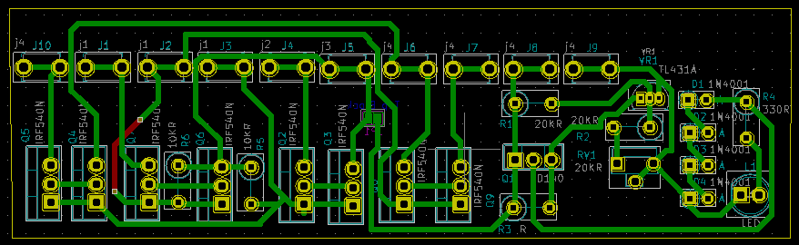
Switcher circuit for 48v Gcell. Cell row 15 BMS at the right with BMS cell rows 1 to 14 BMS boards not shown.
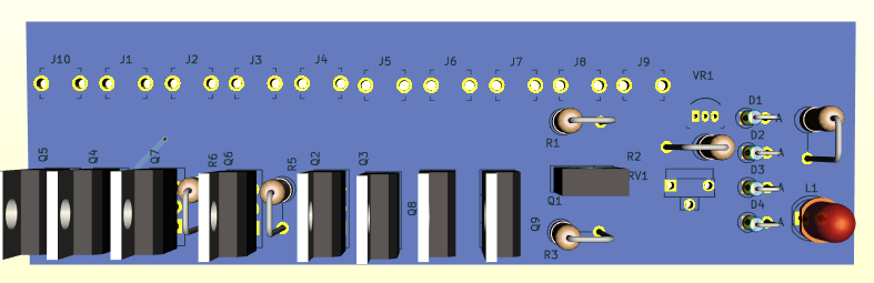
Component side of the switcher. There will be 7 x dual row BMMS replicating the right side BMS
Chapter 13 EV Drive system & Inverters
When I tried to find and evaluate Drive
motors during the first project, The EV Motorhome, my efforts were stalled by the fact that there was so many terms and formulas needed to calculate the need. Also suppliers were a major hurdle. TMG4 out of montreal canada only sells to municipalities and fully qualified OEM vehicle mechanical shops. Siemens has motors if you know the right specs for your need. Then I came across Motovario out of Italy that supplies markets all over the world and publish a huge build to order catalog explaining the specs mainly for their motors but
applicable to motors in general from many sources.
From their catalog, I skipped past the first two sections of the first chapter defining the European regulation and conformity specs. If we were going into production instead of just trying to do a one off to prove the concept this would be more important. Here is the structure
of their motors:
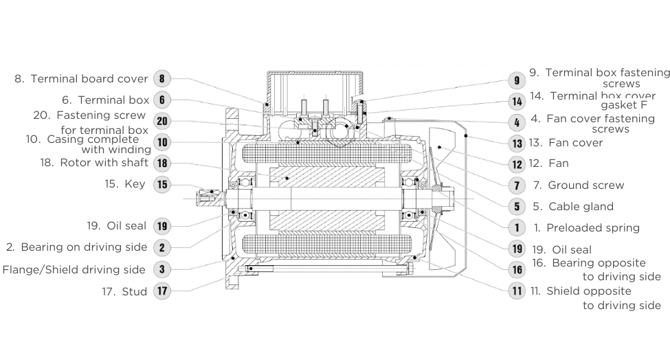 The motors can be flange mounted or base mounted or both. Design variations include high attitude applications, condensation remedies, forced cooling, and load stress due to vertical and horizontal mounting and / or direct drive or belt drive offsets to name a few.
The flange basically conforms to the diameter of the motor without the terminal block and base mounts. So the B5 flange type (no flange mounts) ranges from the smallest 120mm (4.724") to the largest 350mm (13.77"). The B14 flange (with mounts) ranges from the smallest 80mm (3.15") to the largest 200mm (7.87").
MOTOVARIA Catalog of Motors.
1.3 SYMBOLS AND FORMULAS
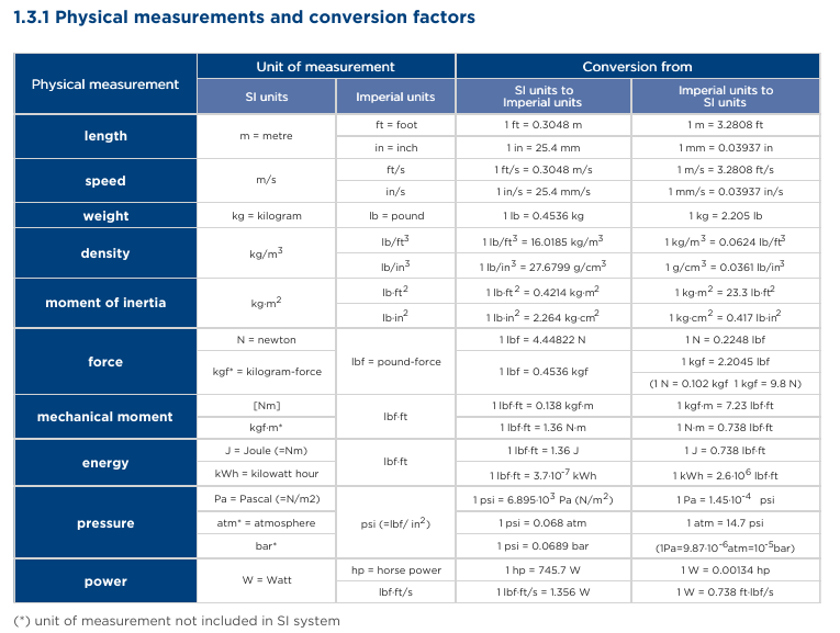
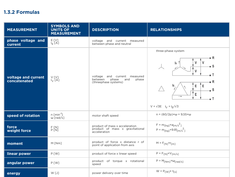
1.3.3 Nominal characteristics
Nominal characteristics: total of numerical electrical and mechanical values (power voltage, frequency, current, speed, power delivery,...) together with their duration and sequence in time, attributed to the machine and indicated on the nameplate, in conformity with the specified conditions.
In particular, the following values in relation to the operation of the motor; the same symbols are used in the performance tables.
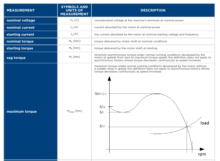
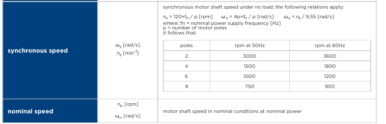
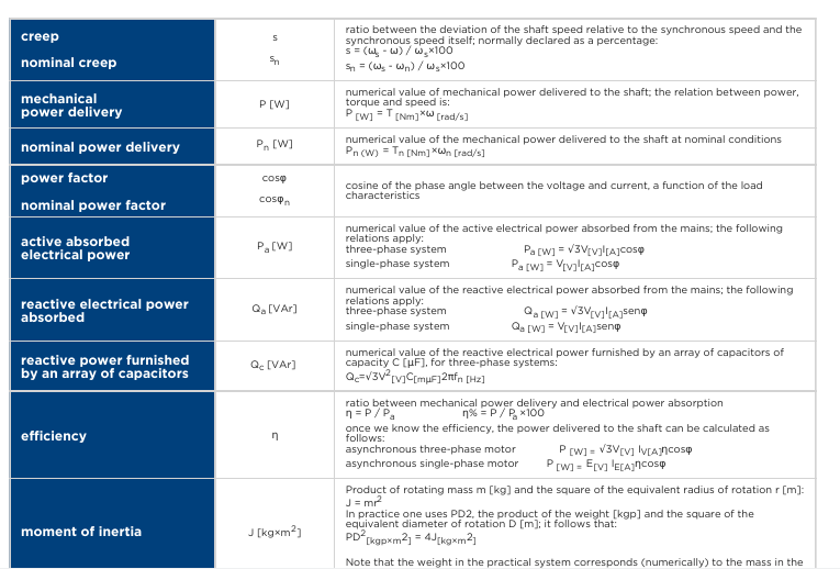
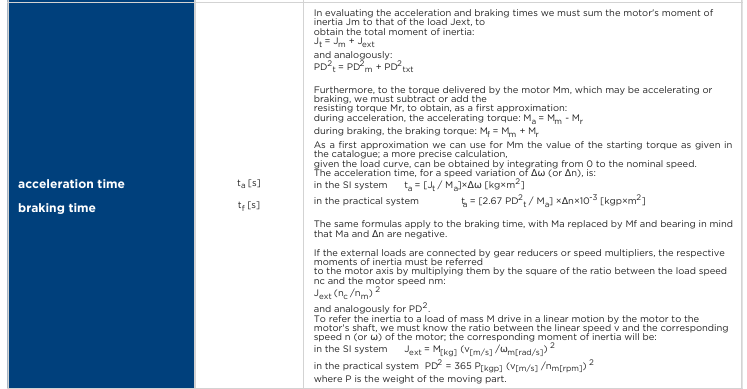
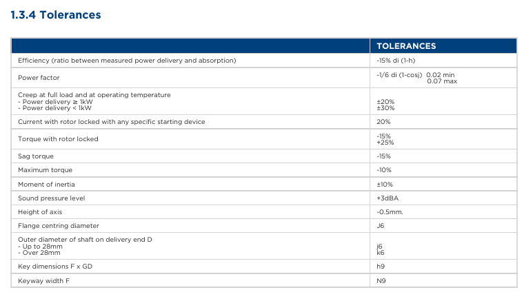
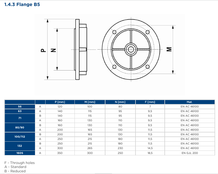 The flange basically conforms to the diameter of the motor without the terminal block and base mounts. So the B5 flange type (no flange mounts) ranges from the smallest 120mm (4.724") to the largest 350mm (13.77"). The B14 flange (with mounts) ranges from the smallest 80mm (3.15") to the largest 200mm (7.87").
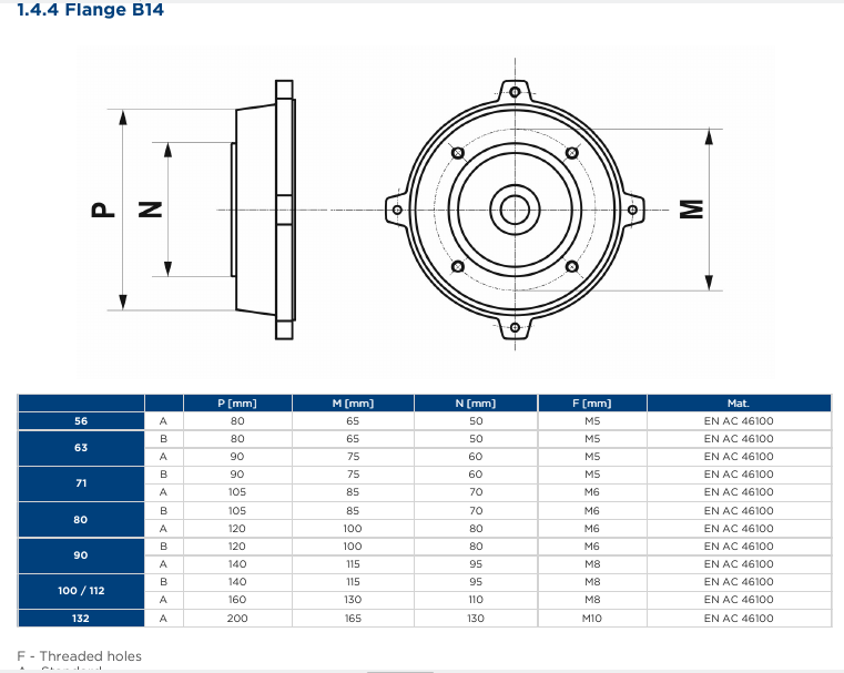
There was many more topics there regarding insulation, thermal properties, operator protection and a whole lot more.
From the research on working with high voltage and the effects on cost of using 6v vs 12v vs 24v vs 48v, The higher the voltage the less expensive are the components and the safer it is for all involved. The revelation came when I realized that if the distance of travel is 24m and takes 300A @ 60 miles per hour, the motor is drawing 5A not
300A, because if it drew 300A from a 600A pack you would only have 2 miles of travel possible. And if you have only one pack and one cell dies you don't move anywhere. but if you have 2 packs and switch over you can still drive with reduced range but your not 100% dead.
Comparing drive potentials
In AC motor drive systems there is a progression. The basics are, an AC source and a motor of 3 phase variety. You turn on the switch and the motor spins to maximum and maintains at that rate. Factors like slip are seldom even considered. The end goal is to have the motor spin at a known rotational for the load it has to handle. The motor has a set voltage it is supposed to operate at and the frequency is usually 60 Hz or 60 cycles per second. At these specs, it has a specific current draw based upon the load. if the load increases rotational speed drops and if it decreases speed goes up. The voltage remains constant and the current
varies by load.
For an EV we want the motor to spin at a varying rate based upon our accelerator. For this we can use VFD (variable frequency drive) or PWM (Pulse width
modulation) or both. Unlike the ICE (Internal combustion engine) which gains torque as speed builds, the electric motor starts at full torque the instant it starts to move. Where the ICE uses a transmission to move through drive ranges and change in direction, The electric 3 phase switches windings to alter direction of rotation and the properties of the AC wave to supply the range of rotational speed. If the maximum rotational speed is different than what is required, a gearbox is used to match motor to need.
Under variable frequency drive the number of cycles is varied to speed up or slow down the motor. If 60 cycles = 3500rpm, 30 cycles = 1750 rpm, and 120 cycles▪ = 7000rpm. So the change in rpm changes the speed
of the drive. Under Pulse width modulation, power is applied for only a fraction of the cycle which has the same effect. The motor starts to spin because it got a shot of power then naturally retards because of power loss. Being AC power, there is a positive part and negative part of a cycle so what is done in the first half should be replicated in the second half of the cycle but it doesn't need to be. The drive controller in many instances monitors the stater position to justify that the cycles or part thereof matches the expected to the actual. Slip occurs when the load on the motor such as hills and valleys vs flat ground effect the rotational position. The controller
under such circumstance must make compensation.
The windings in a 3 phase motor, when activated by a 3 phase supply produce a rotating magnetic field in the rotor area of the motor. Swapping phase A with phase B re-orders the fluxes so that the flux rotates in the opposite direction. Swapping B with C does exactly the same thing as does swapping A with C. Think of it like a triangle with corners called A, B and C. If you swap any two corners and follow the points A, B and C you'll go in an opposite direction. Swap two more corners
and you're back to the original rotation.
Chapter 14 EV Truck Solar Charger system
This is the third solar system I am doing. The first was a 10 panel auto tilt system for the EV Motorhome, The coach system handled shore charging and solar panel alignment and charging. System 2 was for an EV-Tricycle and provided supplemental operating power for the batteries, range extension, charging. The panels in this case could be folded out of the way for access to a large storage basket. This time we will do a permanent roof top charging array on a truck. As with the motorhome system, charging will be 57v but due to less area for panels, will not have 20A charging. In our truck situation we are limited to 4A.
Solar Charged
Solar charging is a method of charging Batteries using the power of the sun. While It can be designed to charge at any voltage, typically they are made for 48v systems and use a charge controller and can handle up to 4000 Ah given the right equipment. How effectively it charges is dependent on size of panels, number of panels, available
sunlight and hours of sun exposure.
Applications are also wide ranging. There are small panels ideal for portable use to charge small electronics like cell phones, PDA's, iPads, and Laptops. Larger panels can be used on vehicles to either keep a full charge on a battery such as Lead-acid, Ni-Cad, or Lithium ion Phosphate. Going with even larger arrays of cells you can do more than just charge maintenance. The Larger arrays may even replace the need for shore power on RV's, or work as a back-up system on brick and mortar buildings.
With the Motorhome we have 110Kw battery pack and with good sunlight could achieve 20A charge to replenish batteries in about 15.6 day from empty. In comparison to the EV-Tricycle, we had 60A of battery charged at 4A and could do a full recharge in under 2 days. Now on our EV-Truck, we have 64.51Kw of battery with charging at 4A over 14 days from empty due to only 8 hours of sunlight. With mass of 6800 lbs, and 64.51kw we have 96 miles of range. According to the insurance bureau of Canada typical use is under 34 miles per day. So if you drive to work (17miles or 12%), and sunlight is abundant you could gain back 4.56kw of the 7.74kw used. When you get home you need to recharge 10.92kw = 4.74hours or $1.45. In all 3 renditions, the solar charge is a supplement to shore power charging. In the case of no shore power the solar system could be used. For those tied to Gas hogs or hybrid vehicles and even current fully electric vehicles, they don't have options if there is no charge station before their batteries die or fuel runs out.
Panel Planning
Our roof space is a total of 6.5 feet by 3.3 feet. So maximum space for the solar array is 21.45 sq ft. This can accommodate 306x 4 inch by 2 inch polycrystaline solar cells. We need to obtain 57v per panel which at .5v per cell means we need each bank to be 119 series cells. There can be a total of 2 string sets for a total of 4 Amps for a charging array of 228 Watts. These are the maximums for us to work with.
Acquiring that many cells would reach $108 in cells at $36/100. The panels being on the roof and in the open will need protection from the elements. Panel size and weight also needs to be addressed. Coming inside the Truck we need a control center for the charge system that must handle 120v AC, @ 15A, and Solar charge. The Battery banks provide 384v with taps for 48v, and 12.6v. Our system therefore will need a Raspberry Pi and a monitor with touchscreen, an Automotive controller, and an inverter/converter/charger unit.
 This brings us to the last part of the plan. We must collect all the energy from the panels and get it down to the controller and subsequent battery banks. Point is that to minimize the wiring you want to have as few wires making a journey as possible. Because we are making the panels 57v we have already cut the wiring down from say doing 24v panels and wiring both series and parallel paths. All our panels only connect in parallel so in the end only two wires make the journey to the controller. When the sun is poor or non-existant, a blocking diode in the controller prevents the
battery from discharging through the panels which would destroy them.
This brings us to the last part of the plan. We must collect all the energy from the panels and get it down to the controller and subsequent battery banks. Point is that to minimize the wiring you want to have as few wires making a journey as possible. Because we are making the panels 57v we have already cut the wiring down from say doing 24v panels and wiring both series and parallel paths. All our panels only connect in parallel so in the end only two wires make the journey to the controller. When the sun is poor or non-existant, a blocking diode in the controller prevents the
battery from discharging through the panels which would destroy them.
 As seen to the left, the 14:2 cable comes from the solar array down the rear frame post to the rear compartment. The battery banks located where the fuel tank was also feeds into the rear compartment with 4 to 5 wires. Our electronic processes use 3.3v, 5v, and our automotive systems for lights and fans and heaters need 12v and finally the Motor uses 384v. Typically speaking we need 3A for the 3.3v and 5v lines, and 10A for the 12v line. In the old 'ICE' design it used 12v @ 60A for the systems and 12v @ 600A to 800A for starting.
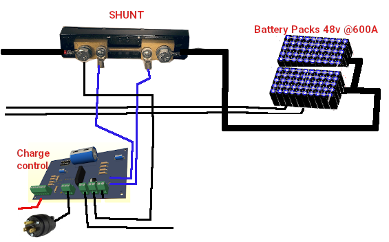 The 384v line from the Battery goes to an inertia switch mounted to the frame at the battery compartment then passes the 384v line to a Shunt resistor before traveling up to the engine compartment. Three wires also come from the shunt resister to the controller in the rear compartment. You can note that the heavier black wires are high current lines that pass outside the interior along the frame and the lighter / smaller black wires are low current that pass into the rear compartment charge controller.
Charge Port at old fuel door.
Ideally, you want to minimize changes made or at least hide them. So in this case I will remove the gas filler along with the tank and put an interrupt switch with plug socket at the filler hole. The interrupter switch prevents drive away if the cable is still attached. It also enables the charge inverter to convert 120v AC @ 15A to 57v DC at 37A. Thats almost 10 times what the solar charge system provides. Alone, it can charge the 168A battery pack in just shy of 36.325 hours. With solar charging it can replenish in 28.59 hours.
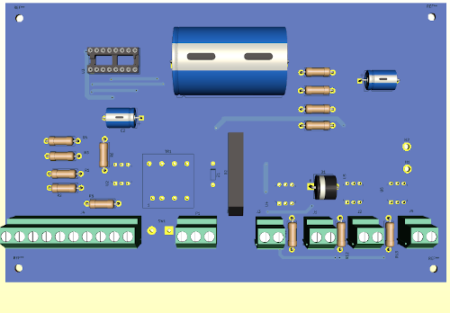 Starting at the left, we have a 10 pin connector that feeds to the console computer. It provides Pol and interrupt signals and shutdwn and clr commands to a charge counter that is coulomb based. It also has +5v, GND, and charge enable lines. Below that is the 120v AC charge line that uses a microswitch at the charge port to indicate when the charge line is pluged in. The AC feeds a transformer and full bridge circuit to supply the charge. U2 is a 15A Triac controlled by the computer to enable charging. U1 is a coulomb counter chip that samples the voltage drop across a shunt resistor connected across two pads at the top. On the right are connectors for the Battery Packs, Main system line, and the solar charge panels. The Inertia switch (not shown) connects between the main line and the Motor Inverter circuit.
Dash computer - Charge control
The coulomb counter sends one pulse each time .00017A pass across the shunt. It also gives a POL signal 0=Drain 1=charge so the computer can see how much battery use has been used or replentished. So as you drive, the computer starts with a full battery 1,000,944 ticks = 168A on a pack basis, but, and there is always a but, we have 2 banks per pack so each bank has 500,472 ticks at full. Each time the coulomb counter gives a tick the full charge comes down by one. So if ticks left has reached 100,094 you have 20% charge remaining. You stop and connect to 120v AC and the computer sees the charging ticks and over a period of time sees it has 500,472 it knows it is full and can stop charging. Because it can read charge from both solar and 120v AC it can see charging action from solar even when driving.
Each basic solar cell has a nominal voltage of 0.48v and depending on size of cell can deliver 0.5A to 1.96A, in the right conditions of sunlight. To charge batteries that are at a higher voltage, you would
place several cells in series to achieve the desired voltage. To increase the charge current, for faster charging, you would connect them in parallel. In this maner, making an array of 5 cells in series by 5 panels in parallel you would get 2.5v at 10A (using the larger 52mm x 104mm cells). This would not be enough for a trickle charge of a lead acid 12v battery. 28 cells in series would be required to provide ~14v but in trueth 36 cells would give best results. Thats 180 cells to make a 10A 12v charger.
The standard Photovoltiac cell is 156mm x 156mm (6" x 6"). The available cell sizes
- 39x26mm 0.5v .36A
- 52x52mm (2"x2") 0.5v .98A
- 52x104mm (2"x4") 0.5v 1.96A
- 52x156 (2"x6") 0.5v 3A
- 156x156mm (6"x6") 1v 3A
An array to charge the 12v Battery with 36 cells would be 2016mm (80") long including the cell spacing and 4" wide. It could be configured as 2 rows of 40" or 4 rows of 20". At 2A it would take 30 hours to fully charge a dead 12v 60Ah lead acid battery. Given that the sun is up only 3 to 9 hours a day, it might take the array 3 to 10 days to fully charge the battery. This brings us to the next hurdle. What happens when the sun goes down? If you connected the battery directly to the solar cell for charging, the battery would discharge through the cell when there
isn't enough light. This is bad for the cell and for the goal of having a charged battery. Using a diode, which conducts power in one direction only, we can prevent this discharge when the sun goes down.
The charge controller is a device that is used to match the panels to the battery system and handle the charging operations. They are normally listed by wattage rather then by voltage and current. So for our 12v 60 Ah battery, we have 720w (12 x 60). The controller may do more than just prevent discharge when the sun goes down by configuring the panels (in watts) into a specific output voltage for charging and regulate the current coming from the battery or going into the battery. Often this includes overcharge and overdrain technolgies. You don't want to keep charging once the battery is full or to continue draining from the battery once it is too low to supply power.
Panels themselves, are made of either monocrystaline or polycrystaline cells. monocrystaline do so in a much smaller panel than the polycrystaline ones and are more expensive. The Panels themselves are fairly thin but mounted to a heavier structure or frame to give it strength in adverse weather. For optimum efficientcy you need to keep the panels clean from dirt and debris. Often you may find various adjustable mounts for aligning the panels to the best sun quality. Some controllers have the ability to change the angle and direction of the panels for highest sunlight transfer. Before moving on lets talk a bit about cost comparison. A monocrystaline cell can typically cost about $3.60ea and one site is offering 10 for $36. Comparing to polycrystaline the cost per cell is $0.13ea.
Now lets make it happen
Let us look at our truck. It has a 384v 168Ah battery system that we want to charge from a 48v solar. To do this we need to either multiply 48v by 8 to get to 384v which involves a transformer and considerable power losses or we can convert the 8 series 48v blocks into 8 parallel blocks for charging and switch them back to series for running. Method one (transformer) is huge at 10" x 6" x 8" and due to losses is less than 75% efficient. The unit will typically cost over $150. Going with a switching method, we can use 6 mosfets at each of 8 x 48v blocks. Costs come down to $64 or less, weight comes down from 10 lbs to 2.4 lbs, and size comes down to 0 since we use spare space at each 48v block to put the mosfets. The second method serves both 120v AC charge and our solar charge at the same time.
With our charge delivery plan worked out and knowing the solar source voltage is to be 57v it is now a matter of cell arrangement to achieve the voltage and as high a current as space permits. Because our Blocks are 48v, we need 57v to accomplish charging. Polychrystline cells are 0.48v so 119 cells are needed in series. With 1/8th inch cell spacing, we need 253" or 21.08ft.
 We can run 10 columns by 24 rows as shown. Each column of 24 cells wire in series with 0.125" spacing. Columns are also 0.125" spacing. Row 1, 3,5 have (-) at the top, row 2 and 4 have (+) at the top. Row 1 (+) connects with row 2 (-), Row 2 (+) connects to row 3 (-), Row 3 (+) connects to row 4 (-), Row 4 (+) connects to row 5 (-) and Row 5 (+) is +57v @2A. Row 6 to 10 do the reverse to make a second set as +57v @4A total.
Step 1: We can make two box frames 21.75" x 54.125" or one frame 42.5" x 54.125" using 5/8" U-channel.
Step 2: 1/2" plywood back plate(s) cut to fit.
Step 3: On the plywood surfaces we need to mark out 2.125 x 4.125 squares into rows and columns observing there must be a 0.5" border around the edges and room at either end for wiring bussbars.
Step 4: Glue a 1/16" thick x 1/2" edge strip to go all the way around the plywood outer edges.
Step 5: Cut a 1/16" UV plexiglass lens to fit
Custom solar Panels
Basically you have UV protected Plexiglass about 1/16th" thick covering a 1.3mm thick fragile solar cell and backed by a rigid backing that may be 1/8th to 1/2" thick sealed in an environment tight frame.
Dirt, grime, and moisture are the main culprets to the demise of panels from an environment standpoint. This is especially true when making the panels. From the in use perspective, you want a strong construction that is light in weight and not prone to bending. You must never let anything especially fingers touch the surface of the cells. USE NON-COATED INSPECTION GLOVES when handling these cells. They are fragile and easy to break. A well made panel has a life expectancy of 15 years. So lets look at what you need.
- 1/16th" Thick UV Plexiglass 43" x 54"
- 4'x8' x 1/2" Plywood
- Silicon clear caulking
- (238) 4" x 2" polycrystaline Solar cells
- 1 spool tapping wire
- 1 spool bussing wire
- 1 spools Red 20ga wire
- 1 spools Blk 20ga wire
- (2) 5/8" x 1/2" 'U' channel 8'
And for tools:
- Lexan cutter
- 3 ft ruler
- speed square
- Drill & bits
- Flux pen or solder paste
- 60/40 solder
- wire stripper / cutters
- 60 watt soldering iron
- Marker pen
- Multimeter
Down to Business
We are going with a sealed aluminum frame design.
Before we get started assembling cells lets actually do the frames as previously described. You can secure the 1/16th inch plexi to the plywood and fasten the plywood to 3 of the frame edges from the underside. Seal the mitred edges with rubber cement. Using the lexan tool you can score the Plexiglass and make a clean break.
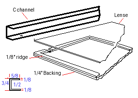 First Dry fit: With our backings all ready we should be able to place the Clear plexiglass onto the frame and fit the 'U' channel over them for a very tight fit.
Our custom array will mount to the roof. 14:2 electrical wire will pass from our panel through the roof at the back and down one side of the rear truck frame.
Wiring path
We are going to have 24 cells on each column and 5 columns per branch with 2 branches per panel.
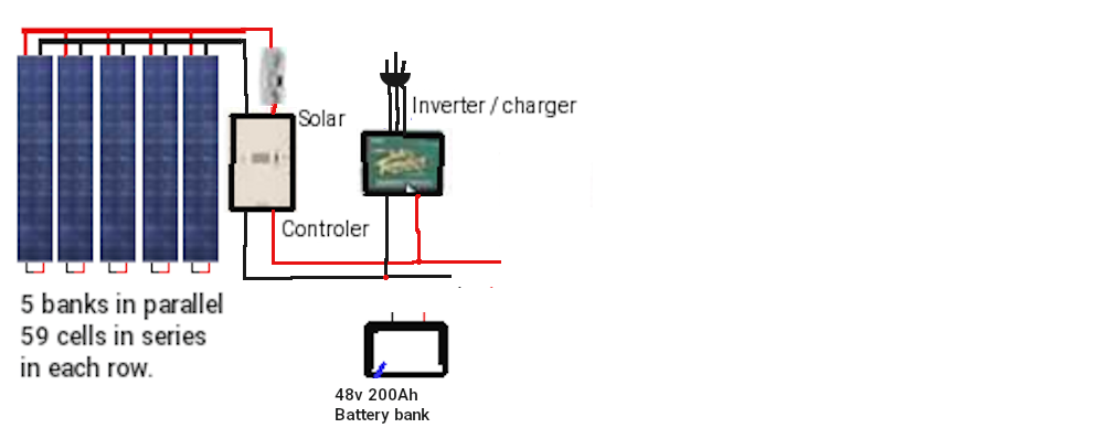
Here is the diagram of a 5 bank system. Ours will be a 7 bank system. This solar controller then feeds onto a main buss. which connects the charger and Battery bank. A master contactor and an Inertia switch run in series with battery (+) to provide power during normal operation or defeat power in a crash. The main power feed comes from the contactor to the dash computer and motor inverter and automotive systems.
Wiring up the cell Banks
It's about time we get to making the actual solar array. We have 238 cells to configure into 10 columns of 24 cells. Gloves on!, make sure your area is clean and open the package of 300 cells. Grab your multimeter, A piece of copper PCB and some wood to make a little stand. We will want to take a piece of plywood about 5" square and place a small 1"x2" by 5" along one edge and
2"x2"x5" piece of wood along the other edge of the wood square. Then place a copper shiny side up angled between the two pieces of wood block. As we check the cells we will lay the dull side against the copper such that the positive cell contacts the copper. In this way we can check the voltage and amps of each cell easily.
The cells will have 6 positive contacts on the dull side and two negative strips down the blueish face. If you bought tabbed cells each cell will have tap wire soldered to the facing. If you bought plain cells you will need to solder tap wire to the facing. But for now, just place the cells one at a time face up on your jig and measure with positive on the copper and negative on the face strips looking for .48v and again for 1 to 2 amps depending on sunlight.
Tap stripping the cells.
For each cell pair we need the tap wire to cover the negative strips on the face and connect to the underside positive contacts. The tab wire does not need to pass past the end of the next cell. So 2" is all you need given that each must be spaced 1/8" apart. If you bought tabbed solar panels you only need to trim the tab wires to 2".
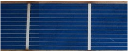
After you have got your work area setup, and tab wires cut to about 4.125" You are ready to start soldering. The soldering iron I use is adjustable from 10-100 watts, I have it set for 40 watts. Be sure that your iron tip is clean and tinned properly, as you work keep cleaning the tip because a dirty tip will possibly contaminate the process.
You see in the picture there are white stripes from top to bottom. These are where you will attach your tabbing wires. The tab wire is not completely at the top of the solar cell. This is just to be sure it does not contact the cell that will be above it.
- First you need to use the flux pen. put a light coating of flux on that white stripe. You see the darker blue areas, that is flux that flowed off the white stripe.
- Lay your tab wire on this stripe.
- Using a soldering point tool (or something similar) to hold the tab wire in place. don't press to hard, you might crack the solar cell under the tab wire.
- Moving from top to bottom, use your soldering iron and start soldering the tab wire down. Don't let your iron set in one place to long, you will burn the solar cell. You will need to move your holding tool around as you move the iron down, don't let the tab wire move. Hold the tab wire down until the solder cools.
- Repeat for all tab wires on each cell.
Cell inter-connections
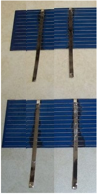
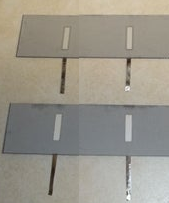
As you have enough cells tabbed to do 5 columns (119 cells) we need to interconnect them one row at a time. Remember the blue face is negative and the back is positive. The back may have either 3 contact spots in two rows or 2 partial strips.
- Flip over all the cells that need to be connected, and put flux on the white areas.
- Lay the tab wires from the top cell onto the back of the bottom cell. All cells need to connected front of one cell, to the back of the next. This puts them in
series. And keep the cells 1/8th inch apart and tab wires must not extend past or even close to the ending edge.
- Solder the connections.
- Repeat until you have all 24 connected.
These cells need to be connected in series because each cell produces 1/2 a volt DC. We are making a 57v panel so we need tie them in series. This is a "no load" reading. When these cells are put under a load, such as charging a battery, the voltage should drop a bit. When all 5 series string are connected, we should see 57 volts.
Connecting cell Rows
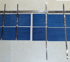
We are making 1 panel with 2 banks of 119 cells in series. Now I will show how to connect 2 strings together.
As I stated before, cells need to be connected front side to back side. On the end of the string you need the 2mm tab wires protruding from the ends of the 2 strings you need to join. You can use shorter tab wires for this if you want to.
- Add tab wires as needed to the end of the strings.
- Lay the strings next to each other with a small space in between them. I would recommend doing this on the glass you will be using for the solar panel, or on something that these cells can be kept on until they are ready to be put into a panel.
- Measure out the length you need for the buss wire. Then cut the 5mm buss wire to your measurement.
- Use the flux pen on the places that the buss will be attached. You only need to put flux on the tab wires, not both tab and buss wires.
- Line up your buss wire on one end of the tab wires. The buss wire does not need to stick out over the end, just make it even. Keep it close to the cells, but do not touch them.
- Work your way from the first one you soldered, keep the buss wire flat as you move.
- After you finish soldering, cut off any of the wire sticking out past the ends of the tab wires and the buss wire.
In the picture where the extra wire has been trimmed off you see an extra tab wire on the left string. I put that tab wire on there to test the cells to be sure they were connected. I stated earlier that cells produce 1/2 a volt, so 4 cells should be 2 volts. I was sitting under a incadescent light when I tested these cells. I got a reading of 1.4 volts. That is very good since most cells will not work unless they are exposed to real sunlight.
Remember when testing and connecting the wires that will run out of the panel the top side of the cell is negative, and the bottom is positive.
End of strings
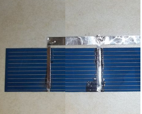 In addition to connecting strings you will also need to put a buss wire on each end of your cells. This is done in the same way as connecting 2 strings, but you are only connecting the 2 tab wires on that one end cell. But on other end you are connecting all 4 wires to the buss wire. I leave a little extra hanging over on the ones on the top. I do this so that when I add a copper wire that will run out of the panel I can fold the buss wire over the copper wire and solder it together, making a stronger joint.
The buss wire can be done before or after connecting strings, that is up to you.
Panel assembly
With luck you have two strings made in series with 1/8" spacing between each cell and each row. At one end you have two buss bars and at the other you have one long buss bar. So now take your template and transfer the markings for the bottom to the plexiglass (frame is taken apart for this). I would put a center hole through the template for each of the cells and then mark the back plate where we need to put a drop of silcon sealant. remove the template and apply the sealant. Now carefully position panels observing that you place them the right direction with the double buss bar at the top. You might want to also put sealant under the bottom buss bar. DO NOT PRESS TOO HARD on the panels or they will break.
Apply silicon sealant to the U channel (one with the wiring holes) and place the frame piece into position. Use a 1/16th piece to simulate the lens for now. Feed a Red wire through one of the holes and extend it across to the left buss bar at the top. Strip and solder the Red wire to the buss bar. Next Feed a Black wire to the other buss bar and strip and solder it. Where the Red wire goes all the way to the other side of panel array, this black wire needs enough length to feed into the next panel and to the top left set of rows. About 25 inches should be plenty. Cut and feed another black wire into the panel and back out. this wire will also go to the other side. Apply silicon sealant to the hole inside and out to seal it from moisture. Use a piece of tape to mark the wire that goes to the other side.
With this done you can now assemble the top and bottom parts of the frame using silicon and the 1/8th" spacers. Remember to also put silicon sealant on the ends of the frame too. Flip the frame over and using a small pilot hole drill 1/2" mounting holes around the frame and put in 1/2" #6 roberts screws to secure the frame pieces. Lastly slide the lens (with protective cover removed) into the frame from the open edge. Silicon and install the final U channel and drill and screw it from below. Now seal around the Plexiglass where it meats the frame. 1 Panel Done!
Chapter 15 Charge / Discharge Control
Battery capacity
The amount of charge that can be delivered into or out of a battery, is important in the determination of available charge for use. We can measure voltage and get a very basic determination because the voltage will drop as the charge is depleted. We can measure the current being taken from or put back into the battery but it really doesn't tell us the total capacity full and how much is left. A coulomb is in the unit of 1 Ampere-second. Another way to put it is the amount of Amperes that can pass a certain point in 1 second. Because there are 3600 seconds in an hour, one amp hour equals 3600 coulombs:
1Ah = 3600C
Measurement by Voltage
We have this 3.2v Lithium cell during charge we can charge it at a maximum voltage of 4.2v at the risk of shortening it's cell life. We can also reduce the charge voltage to 4v and take longer to charge the cell which is safer. Once fully charged and the cell has had time to rest we can measure the voltage and see about 3.2v on a good cell. If we keep monitoring the voltage and start using the cell to power something, we will see the voltage drop and can stop the cell from further discharge when the voltage reaches 0.62v. At a steady current draw, The cell will deplete faster as the voltage drops. So you can see this method is great for the cell when it's only going to be depleted near the top. So if our 12v Battery is fully charged it shows slightly more than 12v and can deliver full current until it reaches about 75% then it starts a slow decline in volts to say 11.6v. It is still delivering the current (amps) but now starts to decline faster and by 50% is now reading 9v. A even shorter time later it is at 15% and well below 5v. To you the operator with just a voltage gauge to go by you traveled 25 miles in 15 minutes showing voltage above 11v. The next 15 miles you got down to 9v, and then you went another 6 miles and your battery is almost history.
Measure by Current
Years ago, automakers made the decision to stop putting analog current meters in cars because of the huge risk of electrocution by passing 60+ Amps into the dash where occupants are. This was for the time the best way to determine battery health. It allowed an operator to read the draw of current going into or out of the battery such that if the meter said discharge 12A you knew you were at that time using 12A of power. If it said charging 12A you were refilling the battery with charge at 12A. Your biochemical computer (Brain) could kind of calculate based upon voltage and drain how far you could travel. But once more it didn't really tell you how much charge was in the battery. You know it's not like a clear water tank where you can look and see how full it is. Today, we use shunts to make measurements like this safely. With a shunt, a very small value of resistance is placed inline with the power wires and we measure how much the voltage drop is across the resistance. Because the voltage being measured is so low and the current through the resistance is also low it is safe. We can now measure the current entering or leaving the battery. We still don't have a way to see the level of charge in the battery. We can see fluid levels but those darn electrons are too hard to see.
We just can't see electrons
It's like they are sub-atomic. Oh my gosh that's right they are! So if we set up a clear barrel and call that a battery. Attach a hose and call that our power wire. Put water into that hose and call that our voltage. And then depending on how fast we fill the barrel (pressure) and call that our current. We can visually see when the barrel is full. If we put a water meter inline with the hose we can measure the amount of liquid that has gone into the barrel. Then when we start taking water(voltage) under pressure (current) out of the barrel, we can again count backwards using the meter to know when it is empty. Based on the full reading and the empty reading we can tell how full or empty the barrel is. That in a nut shell is the problem at hand. We need to count charge going in until full and count charge coming out until empty simply because we can't see how much is in the barrel (battery).
Measure by Coulombs
We are going to investigate how the LTC4150 Measure's Coulombs.
The LTC4150 is the electrical equivalent to the liquid flow counter of the last paragraph. The LTC4150 has an output pin called interrupt, or INT for short (the line above the name indicates that this is an
"active low" signal). This line is normally high, but will pulse low each time 0.614 coulombs passes through the device (which also happens to equal 0.1707 milliamp-hours or 0.0001707 amp-hours):

1 INT = 0.614439C
1 INT = 0.1707mAh
1 INT =
0.0001707Ah
Or to look at it another way, you will get 5859 INT "ticks" for each amp-hour:
5859 INTs = 1Ah
Keeping Track of the Charge in a Battery
As you know, battery capacity is measured in mAh (milliamp-hours) or Ah (amp-hours). If your battery holds 1 amp-hour when it's full, you can continuously draw one amp from it for one hour before it's empty. You could also pull 1/2 amp for two hours, or 2 amps for 1/2 hour, etc.
Using our favorite tool the computer we can enter the maximum capacity of the Battery pack in Ah (Amp-hours). We can then monitor the ticks and direction from the device to add or subtract from the full capacity. Compute the two values in real time to inform us how full the battery is. It has more implications than that too. When charging the value can tell us when to absolutely stop charging so as not to overcharge the battery. It can also tell us when we can't go any further without damaging the battery.
Because it measures amp-hours as you're using them, the coulomb counter makes it very easy to keep track of your battery's state-of-charge (how full it is):
To use a coulomb counter you need to use it with a computer and the people at sparkfun have developed a circuit board for just this purpose that can be used with the Raspberry Pi computer, Ardunino controller and other such devices.
First, assuming you're starting with a full battery, set a variable to your battery's initial state-of-charge (e.g. 1000.0 mAh).
Listen for the "tick" (low) signals from the INT pin. Each time you detect a tick, check the direction signal, and add or subtract the above per-tick mAh value (0.1707 mAh) to your battery-state variable.
Head on over to https://www.sparkfun.com/products/12052 for a complete run down on the use of the coulomb counter and sample code for the Arunino type controlers.
For battery sizes greater than 1 Ah you would adjust the number of ticks to # of Ah * 5859 ticks. So 2Ah = 11718, 20Ah = 117180 ticks and so forth.
* Note that in real life it takes a bit more current to charge a battery than you'll later get out of it. This is because the chemical processes that store charge aren't 100% efficient, with the excess turning into heat. The amount of loss varies depending on the type of battery, charge rate, age of the battery, temperature, etc. You can account for this by providing a manual "reset" input when the battery is fully charged, or doing some calibration to see how many more ticks you get when charging vs. discharging (though this will change with battery age, temperature, etc.).
Bonus: Determining Average
Current
An additional (and entirely optional) trick is that if you keep track of the time delay between "ticks", you can back out the average current used over that period. The equation
is very simple: mA = 614.4 / (delay between "ticks" in seconds)
Note that because this number is the average current use over the time period, the instantaneous current could be higher or lower. This is also covered in their example code.
Connecting the Hardware
The LTC4150 Coulomb Counter IC has a very simple interface. It has an INT (interrupt) output that is normally high, but will go low when a given amount of current has passed through the device. There is also a POL output that tells you which direction current is flowing.
Max Ratings:
The Coulomb Counter can accommodate power sources up to 8.5V, and currents up to 1A. It works particularly well for single-cell (3.7V) Lipo batteries, LiFepo4 (3.2v) up to 1000mAh.
So on their site, they explain the straight forward way to connect this handy device to the Arduino using it to power the board (IN & GND) and the passing of signals from the counter (/int & POL) and
from the controler (/Clr & /ShtDn)
Under this scheme, The battery source goes to the input (IN) and the load connects to (OUT). If using a charger as well to count both charge and discharge the charger goes on the (OUT) side.
But my Pack is 12v @ 20Ah or 48v @ 100Ah
Traces on the board and the LTC4150 can't handle more than 8.5v and / or 1.6A so what can I do now? They say there is no easy way to handle higher values more easily, but, and there is always a but, it can be done. But first lets talk about Interupt vs Polling. Using interupts is fast and assures the most accurate counts where as Polling means you check it at intervals and hope not to miss counts. To poll the device you need to open the SJ1 connection so that if an int occurs it stays low until the CLR is pulsed low. If your code is too slow to react you will miss counts under polling.
By default, the Coulomb Counter is set up so that the INT output will go low and immediately return high. It will only be low for a few microseconds (millionths of a second!), which is enough for interrupt-based code to detect the falling edge, but random checking will almost certainly
miss such a brief signal.
Wiring the Hardware
Here are the minimum required connections for the example sketches.
If you want to try the interrupt example code:
Leave solder jumper SJ1 closed (the default) You will need to connect (at least):
- VIO to VCC
- INT to D3
- POL to D4
- GND to GND
If you want to try the polling example code:
Open (clear) solder jumper SJ1 (Instructions)
You will need to connect (at least):
- VIO to VCC
- INT to D3
- POL to D4
- GND to GND
- CLR to D6
For EITHER version of the code:
Ensure that SJ2 and SJ3 are both open (clear) for a 5V
Arduino, or both closed (soldered) for a 3.3V Arduino.
Downloading the code
The example code is maintained at the Coulomb Counter BOB Github repository. You can download a ZIP file of the entire repository (or clone it to your computer if you have the github software installed), or save the sketches directly.
Changing the Sense Resistor
The Coulomb Counter uses a sense resistor to measure current. This very small resistor (0.05 ohms) is the only component located between the input and the output. The LTC4150 measures the voltage drop across this resistor; thanks to Ohm's law the voltage drop is directly proportional to the current passing through the resistor. This
resistor is known as a shunt. Just like automotive ammeters of years ago, shunts were used to govern very high battery currents to display on very low current meter movements. And this shunt gives us a new way to use the LTC4150
In real life applications you can go with a 0.000083 ohm shunt to achieve 600A in 5859 ticks which means 1 tick for each .102A. But this is untested by me.
Using ohms law you can determine what current flow is through the measurement of the voltage drop across the resistor. As such, if 1v is dropped across a resistor of a value of .05 ohms the current through that resistor is 1/.05 = 20A, changing the resistor to .000083 ohms would drop the voltage under the same 20A load to only .00166v. This is why lowering the value of the shunt resistor works with the current PCB.
* Note that the PCB traces on the board are not designed to handle more than 1.6A continuously, and the JST connectors are not designed for more than 2A.
They state there is no easy way to increase the maximum supply voltage above 8.5v and this is partially true. Typically you make measurements from supply to ground return. This is 8.5v maximum in this case. But if we employ level datum shifting we can accomplish the same thing. Suppose we have a 384v dc Battery in an EV and we want to count the coulombs with a potential draw of 600Amps. Obviously this little board would get fried if you tried. But get this, a 5V zener diode #NZX5V1B_133 in series with a 75k ohm resistor
raises the datum such that the board sees only 5v and the board is happy. It has no idea that the 5v is being taken from the 379v(symbolic gnd) and the 384v supply. Now using a opto isolators device that is suitable for mismatched voltages and currents we can relay the ticks from our 384v system safely through optics to our 5v computer system. We can also control the device the other way. The 75 ohm resistor in this case would need to be a 20watt because of the current and voltage it is having to disipate. The preliminary layout shown later does not take this into account. To handle this situation the high wattage heat generating resistor would need to be mounted
off board.
 As can be seen here the ilq2 quad opto isolator has 4 distinct units in one 16 pin dip package. on the photo diode side we just need to place a bias resistor to either the plus or negative rail and supply our signal to control active high or low accordingly. This would be supplied by the int pulse. The microcontrol side has a similar bias to it's much lower voltage source and receives the int signal to the microcontroller. The same is true for the pol signal it senses the direction of current and tells the diode to go high or low and the
Phototransistor side tells the microcontroller what the result is. For the other two signals we need to go the other way. On the computer side we use the same biasing as we did before and supply the CLR and SHDN signals to the diode and with same precision pass that information onto the high voltage side using the Phototransistors to relay the results to the board. Resistors 2 thru 9 are selected to sink 5ma so to meet with device specs they are all 750 ohms 1/4w.
As can be seen here the ilq2 quad opto isolator has 4 distinct units in one 16 pin dip package. on the photo diode side we just need to place a bias resistor to either the plus or negative rail and supply our signal to control active high or low accordingly. This would be supplied by the int pulse. The microcontrol side has a similar bias to it's much lower voltage source and receives the int signal to the microcontroller. The same is true for the pol signal it senses the direction of current and tells the diode to go high or low and the
Phototransistor side tells the microcontroller what the result is. For the other two signals we need to go the other way. On the computer side we use the same biasing as we did before and supply the CLR and SHDN signals to the diode and with same precision pass that information onto the high voltage side using the Phototransistors to relay the results to the board. Resistors 2 thru 9 are selected to sink 5ma so to meet with device specs they are all 750 ohms 1/4w.
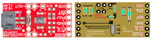 And here we have the daughter board that accomplishes the task with ease.
We have not removed the on-board shunt yet. The blue wires patch our off board heavy shunt resistor onto the Coulomb Counter.
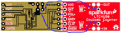 The boards interconnect with ease.
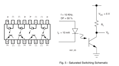 An understanding of the ilq2 IC. Shown is the chip layout and the represented circuit. Both the diode side and the phototransistor side have resistors pulling the inputs
high. They also have cathode (diode) and emitter tie to ground tags. BUT these positive rails and negative rails are NOT the same. On the computer side the plus 5v and ground are that of the computer. On the high voltage side, Plus 5v is actually 384v and ground is a SYMBOLIC ground 5v lower than the 384v. R1 determines the voltage drop value and current supply at 379v @ 50mA. The Zener diode assures the potential difference is 5v at all times.
An understanding of the ilq2 IC. Shown is the chip layout and the represented circuit. Both the diode side and the phototransistor side have resistors pulling the inputs
high. They also have cathode (diode) and emitter tie to ground tags. BUT these positive rails and negative rails are NOT the same. On the computer side the plus 5v and ground are that of the computer. On the high voltage side, Plus 5v is actually 384v and ground is a SYMBOLIC ground 5v lower than the 384v. R1 determines the voltage drop value and current supply at 379v @ 50mA. The Zener diode assures the potential difference is 5v at all times.
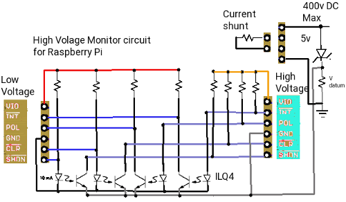 The board is simple having 1 Zener diode, 9 resistors, and a ilq2 quad opto coupler IC. Besides the connections made from the coulomb board to the daughter board, we have just 5 wire pads to connect the external Shunt to the coulomb counter and our computer connects to the 6 pads of the new board instead of the coulomb board. Problem solved.
As designed the daughter board add-on can work with up to 500v and depending on the shunt resistor up to 600 Amps. Because we are Level shifting from the high voltage supply, The board can be used for any voltage from 10v to 500v. The LTC4150 will always see 5v as it's supply. R1 is sinking 379v @ 50ma so it's value is 7.58k. If you supply only 10v as a supply this would reduce current to only 65ua so
the value picked would need to be smaller, like about 100 ohms. The shunt resistor on the coulomb counter board must be removed if doing high voltage. The shunt resistor you will be adding to the daughter board high voltage contacts must be selected such that for 384v a shunt of .000083 ohms (0.083 mohms) will produce a voltege drop across it 50mv and a current of 600A. The shunt resistor would be a maximum of 30w
From the original published specs of the Coulomb Counter They are saying it can count 1A based upon the 0.05 ohm shunt. This addresses that the coulomb board is measuring a voltage drop of 50mv. This modificaton means that instead of getting 1 tick every .0001707 Amperes you will see 1 tick every .102 Amperes which for a high current supply under high demand is still quite useful.
Side note for those who are worried about close proximity of 384v to 5v this a real non-issue. We are taping 50ma from the 384v Battery pack and due to the Zener we are using 5v for control on both sides even though the 5v potential on the high voltage side is taken from the top of the 384v rail. the device is rated for 10 mA with isolation up to 4Kv. That isolation is almost 1000 times what we may see in the worst case.
Using the SHDN Input
You can reset or shut down the LTC4150 by making the SHDN input LOW. This will reduce the power consumption of the board, but the LTC4150 will not measure current consumption in this mode. This input has a pullup resistor; if you do not need shutdown functionality, you can leave this input disconnected. Refer to the LTC4150 datasheet for information on resistor selection. There is also a spreadsheet in the Github documentation folder that may be useful.
Use in an EV Truck
The hard trueth of actual use comes down to 1 discharge and 3 charge situations. While we drive we are discharging the battery bank and potentially charging a dorment bank. When we brake we are charging through regenerative action to the drive use bank. There is also an optional chassis battery bank which would have both charge and discharge happening.
So we are driving and as we start the motor into action there is a 250A potential spike for 1/120th of a second which means we need a shunt resistor to match 384v @ 250A and the coulomb counter needs to see only 50mv so the shunt is 50mv/250A = shunt = .0002 ohms so we will choose 0.000193 ohms to be safe. This shunt needs to be 15w.
We then take our foot off the pedal which cause back EMF on the motor as it switches from being driven to being a generator. The current yuu gave the motor to cause rotation now becomes current caused by the motor rotation. The EMF (electro motive force) is now the wheels turning the motor which generates power. The motor being coil based bucks any change in current so the motor starts putting load on the road wheels which slows the vehicle and the current flows through a full wave rectifier back to the battery. This voltage will be slightly less than the supply with current starting close to full load current (10A) and deminishing rapidly until motion stops.
So you were driving at 60mph and drawing 10A at the motor (230v @ 10A) = 2.3kw per minute. Now your foot is off the pedal and the EMF supplies 200v @ 10A but the current drops as the tires slow the vehicle and in 30 seconds you are barely moving. In 30 seconds you recovered 1kw maximum. The coulomb counter sees the recovered power because the shunt of .000193 ohms @10A = 1.93mv.
Now we look at the battery bank charger it can get solar charge power or shore charge power. In both cases we have 57v at either 37A or 2 to 14A depending on choice of solar power. The shunt resistance in this case needs to be 49mv/37 = 0.00135 ohms if we only allow one charge source at a time, but if we use both the shunt will be 49mv/51A= 0.00097 ohms. Because 48v Gcells are charged in Parallel you must add all the Amp ratings of each Gcell to get the full charge value. 1 bank of 8 @84A = 672A, 2 banks of 8 = 1344A and single Gcell = 84Ah. So 672A/14A= 48 hours, 1344/14 = 96 hours, and 84/14= 6 hours for solar charging, but there is only 7 hours of sun per day. Shore charging is 672/37=18 hours, 36 hours, and 2.3 hours respectively. The single Gcell is an option for running automotive lights and computer from a single Gcell which gives run time of 12 to 42 hours between charges.
EV Charger
The charge controller takes direction from the dash computer and the AC charge port. The computer provides 4 enables (battery pack 1, battery pack 2, Solar, and AC charge). At the AC charge port there is a microswitch that is activated by inserting the plug into the port. When AC shore power is plugged in, it converts 120v AC to 60v AC and if the computer has issued a 'charge-enable' signal passes that AC voltage on to a full wave bridge rectifier to produce 57v DC for charging. As long as the AC charge cable is plugged in normal vehicle operation is prohibited.
Roof top solar panels supply power when there is sufficient sunlight also to the charging system. It can also be enabled/disabled from the computer. When solar charging the counter again is measuring charge in mV from the drop across the shunt. The 2 battery pack enables determine which battery pack(s) to use. Each has a contactor run by the enables. During drain to run the vehicle, a second coulomb
counter notes the direction change of the charge to be discharge and counts ticks of current going the other way.
The limits of the 120v shore power is 15A at source to provide 37A at the Battery packs for charging. The solar array provides 10A. The size of the battery Packs and their current state of charge governs how long
charging is going to take. But, and there is always a but, You can't discharge the Battery Packs less than 20% or they will be damaged. They also can't be charged to more than 98% so full charging range is 109A. If we do as planned to use 2 packs of 84Ah for charge times which will be longer. One last contingency is the solar charge while parked between trips. During time you are parked or stopped, the solar can charge at 10Ah while you dine, shop, or work at a job. So assuming you drove to work and used 30Ah from the packs and solar charged for 8 hours while at work, you effectively only used 20Ah. When you get home total use was 50Ah so your charge time becomes 10 hours on shore power. Costs at 0.17 per kw means it is costing 0.30 per hour for charging. 10 hours to charge to full is $3.06. A substancial difference from $20 a day for gas.
Using an LTC4150 coulomb counter chip and opto isolators configured with datum shifting, we can monitor both charge and discharge of the battery packs. So each time the coulomb counter gives a pulse the computer adds 1 to the tick count for the battery pack if charging and subtracts 1 if discharging. Using two or optionally 3 counters we can track both banks and possibly an option optional third Gcell for chassis features. With the plan for 84A banks on the Car, 492,156 ticks is full and 98,431 the bank is empty (20%).


All connections to the charge controller are on one edge. A 10 wire connection goes from the controller to the dash computer distribution pcb. A microswitch at the charge door connects next followed by the 3 wire AC 120v connection. The power wires from the roof top solar array connects next. Then we have the 48v power to the automotive function board and two sets of Battery pack connection. There are two off board parts. A terzoid transformer is one and the Shunt Resistor is the other. The shunt resistor is due to size and heat it produces and the transformer is just due to size. This board is an earlier single coulomb counter charger. We now use two coulomb counters with an optional third.
Conclusions:
In review of the statistical data obtained however so dated, it is clear that there is some premise for conversation on alternative energy. The 2003 published pie chart below shows 42% of Canada's electric energy comes from non-hydro sources. Wind and Solar is a mere 2% and combined with the 58% from hydro we can assume Canada is 60% earth friendly.
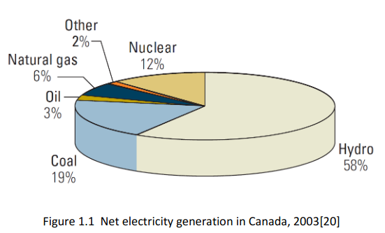
 By taking figures listed in the petroleum journal and mapping them on to the same pie chart shows something interesting. Non petroleum based solutions for supplying our heating and transportation is 18%. Another 6% (propane) might be used for heating and transportation but clearly 76% is Petrochemical and harmful to the environment.
 Mapping the figures from a bulletin on climate action needs substantiates the ones from the petroleum journal showing the exact same percentages as contributing to climate change through greenhouse gas production.
What this has to do with my report here-in, is a demonstrated need for efficient and economical move away from fossil fuels in favor of renewable energy to meet our transportation needs. So now on with my conclusions on an EV Truck conversion.
 The subject of this book was in a general sense the conversion of any North American Pick-up truck into an Solar-EV using a Chevy Silverado extended cab as the subject. The body was aged but sound. Tires, wheels, hubs, rotors, brakes, steering components and axles we assumed passed inspection. This constitutes the bulk of the road worthiness of the vehicle.
Running lights for markers, signaling, brakes, reverse, and license plate will be changed from 12v incandescent to 48v LED and the headlights will remain as original. The following are subject to removal:
- 5.3L 8 cyl engine .... 675 lbs
- Starter .... 6 lbs
- Fuel injector / carborater .... 9 lbs
- Altenator ..... 9 lbs
- EGR, ICM, FICM
- Exhaust manifold .... 10 lbs
- Exhaust piping, Catalytic converter, Muffler ....80 lbs
- gas lines, Fuel tank and Fuel ... 260 lbs
- 12v Battery .... 85 lbs
- ................1136 lbs
as they have no purpose in an EV. The transmission while being kept would be modified into a single permanent gear ratio from it's current 3 speed. The interior will be changed as follows:
- Remove Radio .... 6 lbs
- Remove Heater control .... 1 lb
- Remove Instrument cluster ....3 lbs
- Restructure the Dash for a smooth appearance.
- ......................10 lbs
The vehicle has a curb weight of 4920 lbs and a GVWR of 6800 lbs. As such all occupants (4) and cargo has a limit of 1980 lbs under the original spec. After removing all the above we have recovered 1146 lbs. But we also now have no way to move.
A fresh start
I determined that the best way to power a potential EV-Truck would be a 3 teir approach. In teir one we have a 384v battery pack made up of two 384v banks in parallel that can each be switched in and out of circuit electronically. In teir two we break each bank down to 8 Gcells that are run in series except when they are being charged. Each Gcells is 48v. Each Gcell has 15 series cells to make 48v. Finally, each Gcell is made from type 32700 lithium ion phosphate cells. The third teir concerns power for all electronics except the traction drive. It is the very first 48v Gcell of the first bank of Gcells. This single 48v Gcell has 12v tap used to run lights, fans, computer, pumps windows, accessories.
In charge mode, the Gcell that are in series when in run mode become linked in parallel in charge mode. This takes advantage of a low cost 48v method of charging. Each 48v block has it's own BMS and is charge
monitored for accurate results. There are 8 Gcells in series per bank. 1 Gcell = 15 series cells, 1 Gcell = 14 of 32700 cells in parallel. Each cell has 6A capacity.
Therefore:
- 14 cells in parallel = 6A x 14 = 84A
- 15 cells in series = 3.2v x 15 = 48v per Gcell
- 8 Gcells in series = 48v x 8 = 384v per bank
- 2 banks in parallel = 384v @ (2 x 84A) = 384v @ 168A
- 384v x 168A = 64.51 Kw
- 4920 lbs - 1146 lbs = new curb weight = 3774 lbs
- added dash computer, canopy fusebox , charge controller, Motor & Inverter 175 lbs
- added 2 banks of 8 x 48v battery Gcells 1116 lbs
- added solar charge array 58 lbs
- New curb weight = 3774 + 1339 = 5113 lbs
- GVWR limit = 6800 lbs – 5113 lbs = 1687 lbs for occupants and cargo.
As a commuter vehicle 5300 lbs range = 64.5/0.53 = 121 miles (202km). Under full load 6800 lbs range = 64.5/0.68 = 95 miles (158 km).
@ 32miles/day 17kw to 21.76kw used - 0.384kw to .768kw recovered per 8 hours = 16.616kw to 21kw net used. 120v charge time at home 1 to 2 hours $2.89 to $3.57 per day.
Estimated conversion costs $5400 motor & inverter & controller, $18,900 for 1 bank of Gcells or $37,800 for 2 banks, labor $2000 = $26,300 to $45,200 total cost.
This is based upon DIY pricing but because a conversion facility cnn source at wholesale costs could be as low as $19,300 to $31,000
Compared to the F150 Lightning $58,000 you are getting more bang for your buck.