

Chapter 03 Making an E-Tricycle
This exert from ebook 3 of the Full Time RVer is made as my birthday gift to anyone interested in how an affordable full feature Solar Electric Tricycle can be made. The take away on this project is that as designed 1440watt 48v with 2A to 4A solar built-in recharge and 120v AC built-in 10A charger can deliver fuel free transportation at 50kph with a range of 144kms. It's battery capacity can extend to 96 AH up from 30 AH which can provide for up to 580kms. Hope you find my offering of use. **Please be advised that I am still constructing my E-Tricycle so the Tricycle goes from actual photo's to artistic renditions.**
In the last book in this series we discussed a method of using 3 bicycles to construct an E-Tricycle. Two bicycles we kept the rear triangles for the wheels and reduced height seat pipes with the pedal sprockets and discarded the front down pipes and top pipes and front wheel assemblies. The third bicycle we kept everything from the seat and seat down pipe forward, choosing a bicycle that is a step through (girls bike) design. The intention was to make a solid frame with a custom basket for the back. To mount the two rear triangles to the solid basket frame and secure it to the down pipes of the two outer down seat pipes and the inner Seat pipe such that the pedals could line up to make interconnection of the pedals. But, and there is always a but, to make it work, I found out that a trig welder would be needed (which is not locally available). Also, joining weldable steel to the carbon fiber or aluminum frame components would not be possible except by using bolts.
The bolt method would take a minimum of two bolts at each Down pipe and two bolts at each of the rear triangles. Then the cross brace at the back of the inner triangles would also need a bolted method to secure it. There is not much clearance for this brace to be fastened to a regular bike triangle at the back. The rear wheels also might be obstructed by the bolts. Looking into the topic a bit, I investigated what is available in carbon fiber or aluminum stock to make the frame if I invested in a trig welder and found the only way to get enough stock might be to obtain more bicycles to cut up.
So as I pondered what to do to solve this set-back, I turned my attention to the wealth of left over pieces that would result from making this Trike. 3 bicycles have 3 front tires, 3 rear tires, 3 full frames, 3 pedal sets with sprockets. So it occurred to me that if I make the trailer instead of buying the small available one, I could possibly use up the excess materials. In the next chapter I detail the making of the trailer. And it was that trailer planning that came to solve my problem here. The trailer will use two discarded front tires with steel frame and basket with wheel dropouts designed to accommodate the front tires. A similar frame will make the back of the Trike. The difference being that the trike frame will have dropouts designed for the rear driveline wheels, and instead of the tow bar it will have the mounting for the three seat down pipes. Yes there will be 6 bolts needed (2 per down pipe) but the entire back can be welded as can the bolt nuts to make a very strong structure.
E Tricycle Construction
Rear assembly concept:
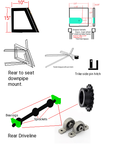
A new square tube steel framework will serve as our rear frame. We make a square lower frame 46" by 36". The wheel wells are now known at 4.5" width and we know the basket will be 30" x 36" so this leaves us 3.5" for side pockets. All framing is done with 0.5" square steel tubing.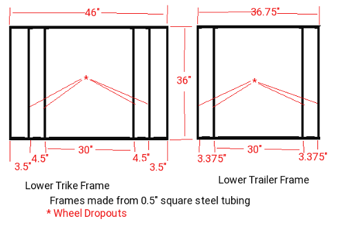
Framing:
- 0.5"x 46" 4pcs
- 0.5"x 35" 10pcs
- 0.5"x 15" 8pcs
- 0.5"x 15" 4pcs (optional)
- 0.25" x 2.5" x 2.5" Flat Steel dropouts
Dropouts are centered at 15" from the Back
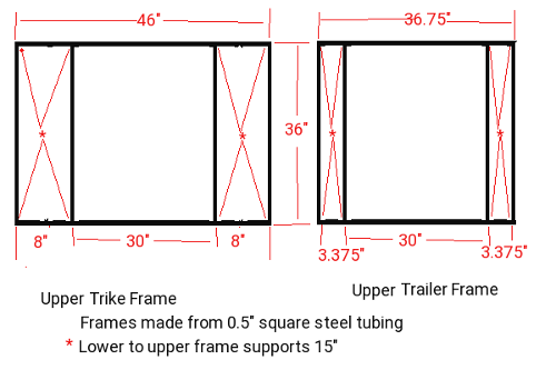
For the upper frame we almost duplicate the lower frame only we don't need the inner wheel well piece. Between the lower and upper frames we put 15" supports at the corners indicated.
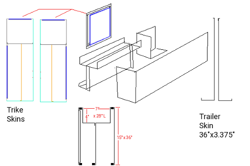
Sheeting panels:
- Inside panel @ basket 46"x15" bent @ 8"
- Wheel well 23.5"x28"
- Upper storage 8"x28"
- Outer storage 36"x16"
- Equipment 8"x 31"
- Equip Front 8"x15"
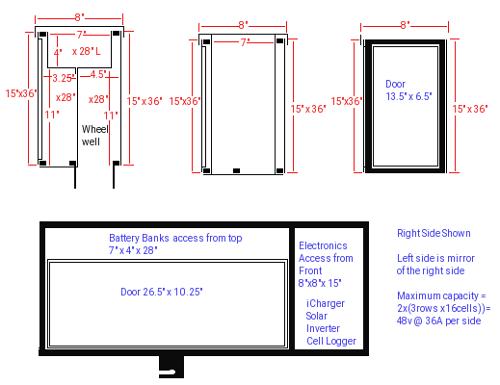
Doors and covers:
- Battery lid is 28"x8"
- Storage door is 10.25"x26.5"
- Electronics Door at the front is 13.5"x6.5"
The upper frame has a Battery compartment 4" deep x 28" x 7" at the back and an electronics compartment 8"x7"x15" at the front, Wheel wells sit at 4.5" wide x 28"Long next to the basket, and a storage compartment 3.5"x28"x11" at the outside.
Other side gets same measurements for panels only reversed.

First bike acquired

The Target Bicycle would have
- 17" Seat down pipe to sprocket ... OK
- 26" Wheels with tires ... OK
- > 1.5" tire width ... Tire width 1.75"
- Front Hub spacing > 3" ... Hub spacing = 3.375"
- Axle mount length .... = 5.25"
Second bike options
With this arrangement, we just need a second bike for the needed Front wheel (for the trailer) and the Rear wheel with fender. We should also get the second rear brake. As an alternative we could just obtain the two tires with wheels and fender and cable brake unit. I am finding a difficulty in sourcing just the parts. Fender found are in front/back pairs for $50 to $200, Pull cable brake calipers seem to be about $20 plus the cables for about $6, Standard front wheel without tire seems to be about $42 plus Tire about $17, Back coaster brake wheel is $72 plus tire at $17. But and there is always a but, mixing a coaster brake with 3 speed hub is problematic. Obtaining a rear hub wheel has 1000's of choices. An electric Trike should have the ability to have electric brakes but such was not found, they are all manual as cabled pinch pads, or manual drum brakes or manual disc brakes. Bummer!So with this getting 2 tires, brake kit, fender, 2 wheels is looking to be about $26 brakes, $59 for trailer wheel with tire, $89 to $600 for rear wheel and tire and fender another $50 to $200. That's a $224 to $785 hit for the parts which buying a cheep single speed bike would complete is $150.
The top of the seat down pipe sits only 28.5" and the seat bottom is 31.5" our back section top of frame will be at 31.5" so we are fine with 12" down pipe to frame support. Due to the angle of the seat down pipe, the seat will overhang our mount by 5.5" which is also very fine. Under these specs, the bottom will be 11.5" from our frame.
To use this bike for the front assembly, we need to remove the top bar side supports and add a support from the lower 12" frame section extending to the front forks for a more usable step thru design. The top might just be long enough to fit the lower support for this purpose. The rear wheel well fender can be re-used for the trailer on one side. So now we just need another bicycle to complete the structure.
Actually, all we need is just the rear wheel and fender and front wheel to make the Trike and trailer complete.
Time for measuring
With an actual bicycle to work with we can now measure things and set the values for making the rear assembly.- Tire width front 1.75"
- Tire diameter front 26"
- Wheel Hub front spacing 3.375"
- Wheel axle front 5.25"
- Tire width rear 1.75"
- Tire diameter rear 26"
- Wheel Hub rear spacing 4.5"
- Wheel axle rear 6.625"
- Pedal sprocket diameter 7.5"
- Rear Gear diameter 3"
- Pedal movement radius 8.5"
- Seat Down Pipe 17"
- Seat height from ground 35.5"
- Seat Down Pipe angle ??
- Front fork Pipe angle ??
- Top pipe length
- Front Axle bolt diameter 0.375"
- Rear Axle bolt diameter 0.375"
Second bike donated to the cause.
A second donated bike made some serious changes to our plans. For starters, it had fat 2" grip wheels at 24" not the original planned 26". The front wheel was quick disconnect and the rear wheel was equipped with a 7 speed sprocket and a 2 speed front sprocket. To use such a bike I decided to attach the dropouts for the rear wheels as changeable. This means I can at a latter date go with 26" wheels if desired. I would drive only one rear wheel and use the front wheel as a rear wheel in idler mode. For manual pedaling I have a choice of which of the 7 sprockets to use. The sprocket chain itself is 3/8" instead of the 1/2" chain needed to mesh with the crank sprocket from the first bicycle. All this means is that when I employ the drive axle, I need a 1/2" 16 tooth sprocket to mate with the front drive gear and a 3/8" 15 tooth sprocket to mate with the drive wheel.Rear assembly construction:
Faced with delays and other obstacles meant there needed to be compromises. Funds for the project were drastically affected when an anticipated availability of $1689 over the year from rebates became a mere $296. The cost estimate for material and welding came in at $500 for welding and $359 for materials just for the trailer and trike rear frames. The Trike would be made originally as a pedal version and latter to a full battery/solar/charger e Trike. Due to delays in getting the project started and lower money available, it was decided to have the shop supply the square tubing and driveline components and use riveted custom brackets to make the frames. Each rivet has a shear stress of 150 lbs so in theory with two to five brackets at each joint and 4 rivets per bracket it should yield 300 to 750 lbs of shear at each joint. The overall weight limits of the rear frame is 1400 lbs and 2" x 24" Bike tires have a GVWR of 2400 lbs. More than a little overkill here as the trike is meant to carry 4 20lb propane tanks as its heaviest load, plus 100 lbs of battery and electronics and me (220lbs). Because 20 lb propane tanks are 40 lbs full we are at a total of 480 lbs. Our tires can support 150 lbs of frame + 480 lbs of load (1/4th of 2400 max). Our frame can handle the weight too 630 lbs ~1/2 of 1400 lbs so we are good to go.First things first. I ordered the square tubing as 25 pieces of 4' x 1/2" square tubing and immediately found that I could only obtain 3/4" or 1" square tubing not the intended 1/2" tubing. For my purposes this is not serious. Dimensions will have to be rearranged to compensate so that the total width remains at 46" and the basket of 30" width. Surprise surprise! Where I planned to cut all the 25 pieces to exact lengths and use the excess to make the uprights from the lower to upper frames, what I got was 23 pieces cut to exact lengths with no excess.
This presented me with new set of problems. The shop explained that doing my project they supplied the metal to the original planned lengths and due to lack of stock did their best and they are too busy right now to undertake more. The original plan was to construct the etrike in April before they entered their busy season, have them weld it all. Now I would construct it with riveted custom brackets and weld latter.
Having less metal to work with meant some radical changes which actually turned out for the better.


I modified the design of the upper frame such that the two side compartments could be removed to service the brakes and wheels. This reduced the needed lengths to 8" on the outer - upper pieces and eliminated the two lower inside lengths to make upright material available.


Using the layout above- right, I first trimmed the main pieces to exact size as some were longer by as much as 1.75". Using a piece of 1x1" 'L' channel I then cut by hand 120 brackets and drilled 4 1/8" rivet holes in each.
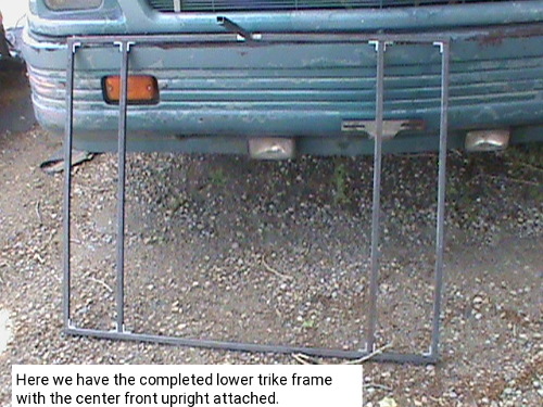
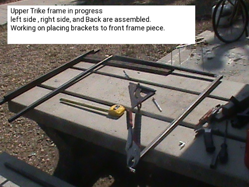
On the left we have the assembled lower frame 36" long by 46" wide with provisions for 8" pocket/wheel wells on each side and a 30" wide basket. To the right we are making the upper frame. The adjustments made to compensate for using 3/4" tubing instead of 1/2" tubing affects the length pieces not the width pieces. So for the bottom frame we have two 46" lengths and four 34.5" instead of six 35" front to back lengths.
The top becomes radically different. It still has a width of 46" at the front, but the back is shortened to 31.5" and instead of four 35" front to back pieces it now has two 34.5" lengths. At the front will be two 8" x 8" sub frames to make the electronic and battery compartments.
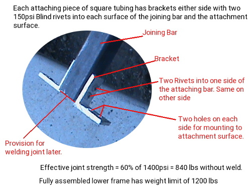

There are few mistakes here that are not critical. We need to handle 640 lbs and according to two different engineering computations one says maximum load is 1400 lbs but written on their site as 1400psi and due to using rivets it is safe to 60% of that limit. The question is raised as why is a welded structure designed for 1400 lbs only safe to 1200 lbs? Secondly, 1400 lbs load is far cry from 1400 lbs per square inch (1400psi). The other computation site gives the results of 1480 lbs for maximum load when welded and 960 lbs using rivets.
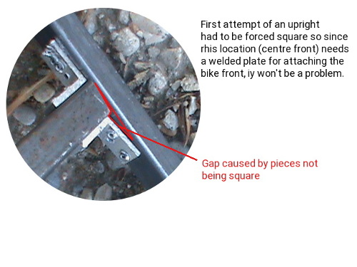

So placing the uprights onto the lower frame we are close to having the bottom finished. On the picture I incorrectly said only two uprights remained to be installed but as you can see there are three to do.
Rear Frame assembled:
Below we have the constructed frame for the rear of our tricycle. First we have the image with the highlighting of the features. It meets all the specs of our design with 4.5" x 28" x 10.5" wheel provisions, 4.5" x 28" x 5" battery packs above the wheels, 3" x 28" x 14.5" storage either side, 30" x 36" x 14.5" basket, and two 8" x 8" x 14.5" compartments for electronics and batteries. In essence we could have 90A @ 48v of batteries to triple our distance although I will be happy to have one 30A 48v pack.

Rear Skins construction:
The Electrical and Battery compartments need to be enclosed. I made a valid change to the plans by deciding to move the front compartment doors to the sides. It simplifies making the side compartments as you will see. Using the repurposed metal skin from an old compact fridge I made two 8" x 22.5" pieces and riveted them on the front and bent around the bottom. Two more pieces 14.5" x 16" were formed to enclose the back and inside side of the compartments.


We have the four angular views of the rear frame with enclosed compartments. The inside skins have to wait till the rear brakes are installed. These last inside skins also need to be removable to service the brakes.
Front of Trike construction


At this point we want to start preparing to add the front of our trike. So first we need to remove the back wheel section of the bicycle. A hacksaw made short work of cutting the back aluminum frame of the bike. I fashioned an attachment frame to connect the trike front to the rear assembly. It mounts to the back using four 2" brackets. two go on the center upright and the other two to the bottom frame.


It's been a long process dealing with very hot days, lots of sawing steel, occasional rain delays and all those 1/2" wide brackets. But it appeared the project was moving ahead. In retrospect, the shop said a cut and welded assembly was estimated at four hours and manually cut and riveted assembly took 30 days ... wow!
Reflections
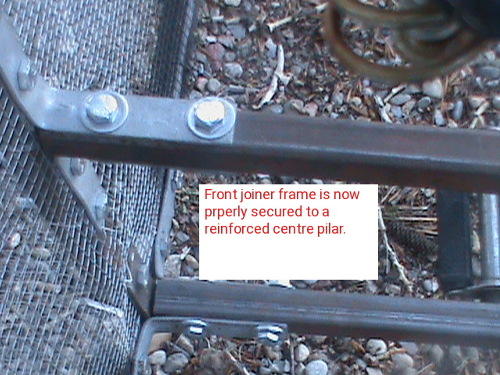
The night after I installed the center post for mounting the front of the trike to the rear, I had this recurrence of a disturbing dream of attaching the front of the trike the rear and the center post busting out at the bottom frame and having to reinforce the post with straps top and bottom. The image shown is exactly what I had in my dream! So when I did attach the front to the back, it was no surprise that the strain did in fact break this center post free. Being bolted together I removed the front section and joiner off the back and took steps to put two 'U' shaped supports going over the top and bottom frame rails and secured solidly onto the center post.

This set back kinda delayed my intention to put the wheel dropouts into place right after attaching the front to the rear assemblies. Since I have the front off again anyways, it is an opportune time to also add the side bracing top and bottom before putting the front back on.


As just mentioned above, I installed two 'U' shaped metal straps top and bottom and bolted to the center post. Latter I will weld the center post so there will be no more issues.
Rear Basket assembly construction:
For our basket we will have a wired mesh front and back and on the bottom. The basket will be enclosed on the sides with metal skin and have a reinforced bottom with a center support and 4 wood straps. The intention here is to allow rain and snow and air to pass through the mesh rather than collect in the basket or add wind resistance.The mesh was laid over the upside down frame and wrapped around the inner side rails, front and back uprights and front and back top rails. Using more thin wire the wrappings were stitched.


Here we see the reinforcing done. There is a center support and 1/2" x 1.5" x 34.5" slats mounted either side of the wire mesh. I took the opportunity to coat the slats with rubber undercoating. The container said rubber asphalt undercoating
Wheel dropouts:
Hand bending metal into tight 90 degree straight angles is not so easy so I decided to use 1/2" 'L' channel bolted to flat iron plates to make the dropouts for the wheels and for the axle bearing blocks.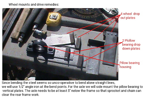
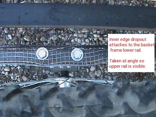
.25" bolts secure the brackets to the frame and 3 3/16s bolts secure the brackets to the plates. 5/8 holes centered at one end of each plate provide mounts for the wheel axles. These holes are then made into slots to make the dropouts.
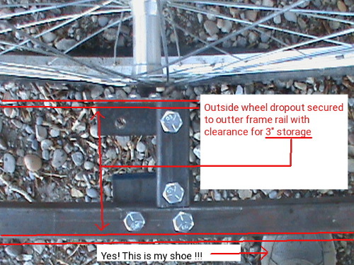
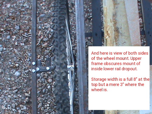
For the outer mounts, we lack a mount frame so at the wheel axle we make a extension off the outer frame consisting of a plate some square tubing and the dropout bracket.
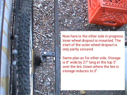
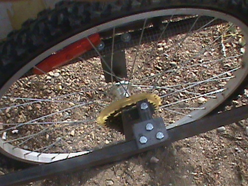
As can be seen, this worked quite well to mount the rear wheels and we have something that now looks like a tricycle!
THE TRICYCLE: Push mode
With front end and wheels attached we have a tricycle that can't be used other than by pushing it. The angle is wrong between the front and back so the front of the back section is not even with the back of the back section. As a push vehicle it worked very well. I was amazed at how easy it was to push and control.


As seen in the last picture, it is a Tricycle with future provisions for Battery, electronics, and storage. It still has front bracing, driveline drop downs, back to front section level adjustment to be done.
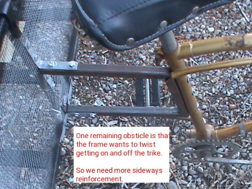
Once the side bracing is in place, it would be prudent to weld this to make one rigid assembly. The seat down pipe is secured to the back by 3 bolts into the attachment frame. As I said earlier the back section is not level, so I will need to remount the front about 3 to 5 inches lower. In a short while you will see that I made an Oops with regards to this. An Oops I might add that could have been prevented had I made the change before testing out sitting on the unit.
Making a step through
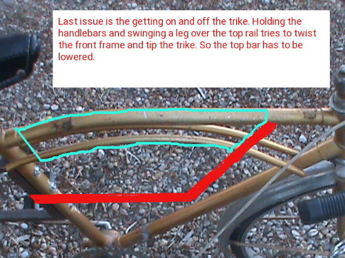
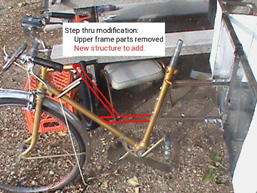
Here is the plan for making a step through frame on our Tricycle. In true fashion I tried to run before I learned to walk. It's a but and there is always a but situation. I cut out the section of frame intended to be removed. But and there is always a but, I returned the seat onto the seat down pipe and immediately proceeded to see if I could step through the frame without it twisting. I didn't intend to actually sit on the seat but as luck would have it did just that! The bottom of the rear mount frame at the seat down pipe abruptly bent and in no small way either. More on this later.
Advance planning:
When the weather is uncooperative provides time to think of upcoming and future parts of the project. I will discuss braking, lighting, and the windshield plans.The first of upcoming/future parts is the concept of having brakes on the tricycle.Brakes
Two types of brake are used. The 3speed had a side pull and retained for the front brake and as an mediator to transfer brake handle to two brakes at the back. The Back brakes come from the second donor bike and are of a top pull type shown. With limited space in the wheel wells at the back the top pull take less space than the side pull.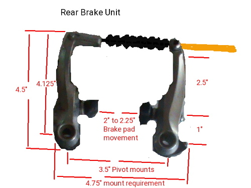
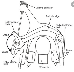
The front remains as is. The back brake line from the brake lever at the handlebars runs down the front frame to the repurposed side pull brake mounted on the joiner frame. The joiner frame is modified to pull two cables going to each of the rear wheel top pull brake calipers. Mounting of all 3 rear calipers needs to be worked out.
Look into other technologies
Other technology might be able to shed light on my concept. For years there has been a move to automated aids primarily targeted at the mobility impaired using automobiles. So I looked for the leaders and came back with undeniable source. aevit automated vehicle integration technology. This company is world class leader in technology to enhance mobility impaired individuals to control a motor vehicle. It starts with the primary functions of steering, acceleration and braking. Then further modification is used to add the secondary functions of turn signals, wipers, radio, phone, lights, horn and others. Basically any car or truck may be adapted without changing the original primary and secondary systems. As such, a vehicle can be operated by normal factory control systems or by the adaptive systems.As adaptive systems go, there are a wide variety of add-ons. Automated door closers, wheelchair ramps and lifts provide for entry / exit needs. Various hand controls types are introduced to accommodate the special needs with primary focus on the three primary functions. Steering by the factory wheel, wheel with suicide knob, and Joystick in a number of designs to control servo's. Electronic Transmission shift coupled with a lever or joystick provide for direction movement (fwd/rev) , Acceleration in the set direction and braking. With the Joystick you can achieve steering and acceleration and braking all in one. For a vehicle these are a major step forward from the simple lever style push rods that merely pushed the gas and brake pedals using a floppy lever mounted at the steering wheel.
Power servos are controlled by Joystick and control circuit to physically turn the wheel for steering, regulate the amount for gas or brake to apply. Simple switches select the gear and direction of the transmission.
But and there is always a but, we are doing an Electric Trike. It needs things to be light weight, steered by the rider, Accelerated and braked by some means. Typically, the right handle grip will have a thumb throttle or a twist grip throttle. Left and right brake levers control the front and rear brakes independently. In a car the brake pedal puts 40% to the front and 60% to the rear for braking, but bicycles can have 0-100% applied to either or both. This means if the front brake locks up you are going to stay in motion and suffer significant damage as you get tossed forward.
Standard bike brakes are either cable, or hydraulic. Cables stretch, fray, and snap. Hydraulics leak and get air bubbles. Calipers are either rim, disc, or drum. With E-bikes, regenerative braking and resistive braking were added. This adds up to 8 styles of braking for an E-Trike.
They each have there good and bad (15kph - 0):
- Cable-Rim
Poor stopping, rapid heating, 3-4 car lengths - Cable-Disc
Better stopping, semi-rapid heating, 2-3 car lengths - Cable-Drum
Better stopping, /semi-rapid heating, costly, 2-3 car lengths - Hydraulic-Rim>
Poor stopping, rapid heating, 3-4 car lengths - Hydraulic-Disc
Better stopping, semi-rapid heating, 2-3 car lengths - Hydraulic-Drum
Better stopping, semi-rapid heating, 2-3 car lengths - Regenerative
Poor stopping, rapid heating, 6-9 car lengths
** may overcharge the battery ** - Resistive
Poor stopping, major rapid heating, 4-6 car lengths
Heat is the problem. hot brakes wear the pads fast, warp Discs, deal poorly with moisture.With Re gen and resistive braking you also get an issue of enormous reverse torque that can twist forks, strip axles and dislodge the wheel from the bike.
So in an E-Trike we need several things to happen. Firstly, we need to cut motor power or switch to re gen when brakes are pressed or throttle is released. The controller actually should do this already if brake handles have motor cut out switches. Secondly, we don't want to short the motor windings as in resistive braking as this damages the motor and creates heat more than it provides more stopping power. Thirdly we need standard braking run from the brake levers to all 3 wheels. It has become a bigger topic than I had planned for.
At the onset, I figured to have the front rim brake stay as is and run the rear brakes in a 'Y' configuration where the right brake handle pulls a cable to mid mounted caliper which then pulls a cable to each rear brake caliper on rim brakes. The front electric wheel has provision for Disc Brakes if fork clearance is ideal. The rear wheels will need to be changed to ones that have disc brake provision as rebuilding the hub is expensive. And this still leaves me with trouble prone Cables or optionally hydraulics with cable activation.
Brake theory elaboration ... Detailed breakdown of braking
Our E-trike is all electric except for braking so maybe we need to improve to electric braking. For this we need Twist grip accelerator pot or lever action pot to control the amount of pressure to apply electrically to a brake actuator. The Actuator can then apply push or pull action to the very short Cable at each wheel. Under such a system, the handlebar brake lever turns a potentiometer with auto return spring. A magnetic reed switch or hall-effect signals when brakes are applied. 4 wires from each brake lever go to a control circuit. The control circuit sends a brake applied signal to the E-Trike motor controller and the pots convert the resistive value into Voltage of a varying amount that powers the actuators at each wheel. Thusly, either brake lever can cause 3 wheel braking. Changing the voltage at the front and back actuators can allow for proper 40%/60% braking. A Pull actuator then pulls a short cable the distance based on the supplied voltage and the cable can now operate the pull caliper of a cable or hydraulic rim, disc, or drum brake.
In retrospect, the maximum force on the lever that a person feels comfortable at gripping for a long duration can be as little as 1-2kg for a child, 3-6kg for a woman and 5-7kg for men. This new pot type brake lever is highly sensitive with 0.2kg - 0.4kg so you do not get the back force of cable adding tension. The actuator is available with 10N - 2500N which compares with a typical man that has 7kg = 70N. As such you don't need a very powerful actuator to provide the cable stopping power of 70N applied to the calipers. This means we have replaced Manual Cables of 4' to 10' with electrical wiring and the actuators can mount as close as 4" from the calipers at each wheel. However for our purpose a mid mounted actuator still removes 5' of cable, cable routing, and modifying a caliper into a 'Y' configuration.
So in normal E-bike design you have throttle, motor cut off on brake levers, battery, and motor control. Brakes are manual via brake levers and cable driven. Lights, horn, charging, and heads up display are after market add-ons. Using after market add-ons it is possible to implement turn signals by wired connection or wirelessly, but these usually have a self contained battery that is low in power and lumins. Headlights can have built in horn if your lucky and of course their own activating switches. The brake lights are generally added by again wired or wireless with again internal battery and yet another switch. Some controllers have a display that gives speed, odometer, temp, battery status, but most do not. After market E-bike displays exist that mount at the handlebars with wired or wireless speed sensor down at the front wheel. Our handlebar can therefore become quite cluttered with Throttle, Key switch, two brake levers, Left/right turn buttons, Headlight switch, horn switch, brake switch, Info display. We need all these but there has to be a better way.
Above we talked about making an electric form of braking. Using a lever Potentiometer with micro switch or reed switch, we can have the switch do dual duty to both cut motor power and turn on the brake lights.
Lights
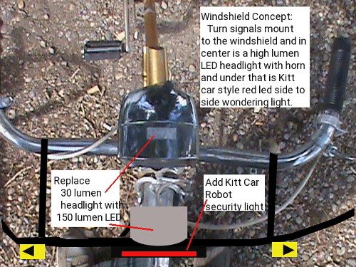
Making custom lights for turn signals, markers, and Brakes allows us to use our main battery and high lumin LEDS to give improved performance. A custom turn signal/horn switch places both in an easy to access location. Headlight, hazard flash, Key switch, display can be combined into a single unit with less demanding space requirements.A lot of lights for bikes with handlebar switches for on/off/turns are either Bluetooth or wifi functional. These have internal battery for operation instead of direct wiring. As batteries wear down the lights become dimmer progressively so really not a preferred functionality. For our electric Trike we have a 30A 48v battery bringing 48V to the handlebar Key switch so supplying 48V to our lighting controls is not a problem and 48v LED lights for our signals headlight and brake lights are not a problem.
This brings us to neat modification. A regular 6v lamp as the donor bike has is only 30 lumens (dim) and at 48v we can go with 150 lumens (super bright) LED and add to that a simple robot light simulating the kitt car or cylon roaming light. In the future one could tie this light into a sensor and security system and people can be chased away with the feeling they are being watched (which they would be!). As we travel, the futuristic roaming red light up front on the windshield moves back and forth but when the Trike is parked and shut down, the roaming light goes out.
As progress develops, we can go further into our end game plans for braking, lights, and control.
Windshield
Next thing to think about is the windshield. We need it to rotate with the handle bar movement, support turn and marker lights, shield not only the face but also hands.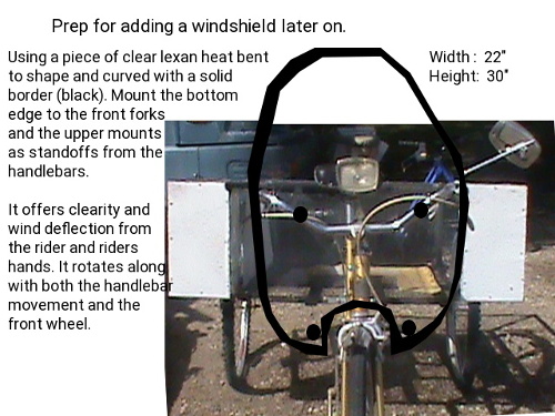
An OOPS! :
Winter prep is rolling in fast! There are leaves falling all over and they need to be cleaned up as well as making things winter ready. So my time is getting shared now between leaves, winter prep and trike progress.

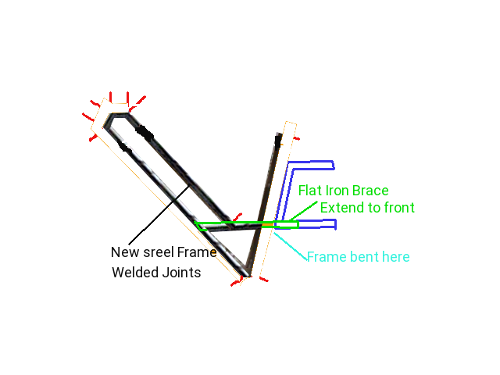
Sitting on the trike before we were ready was NOT a good plan. We had installed the upper twist preventing brace on our front to back joiner. The first picture shows the damage, the second one shows an idea to correct the bike in part. First we need to remove the front and straighten it, then build a sub frame, put in the lower brace and move the joiner frame down lower.



Side compartment construction:
It's a race against time and the weatherman! To make the side compartments, I cut two 8.5" x 36.5" tops, two outer side panels 36.5" x 14.5" with the doors panels cut out. Then cut two each of front, back, storage bottoms, inner walls, upper storage , and basket side upper frame pieces.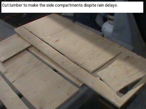
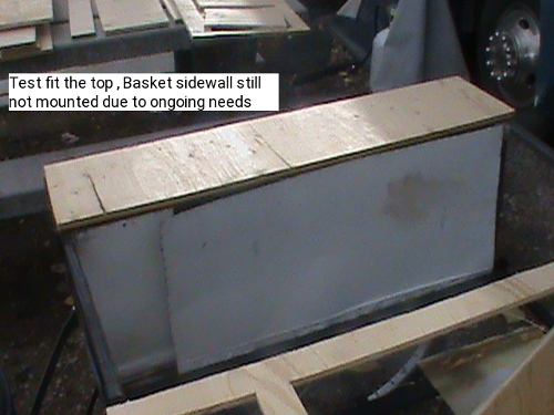
Here we have the side compartments ready to be fit into place. As can be seen they form a kinda fender around the wheels. Ideally, it was intended for all surfaces to be cladded with metal but this didn't happen this year at least.
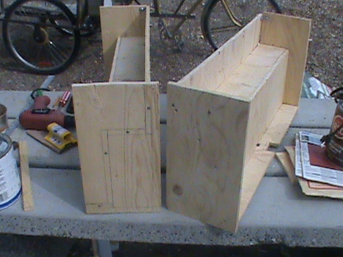
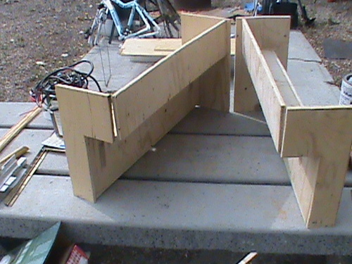
You will note that the side frames have notch outs where the wheels dropouts are. This needed to be done so that the frames could clear the mounting bolts which otherwise would prevent the compartments from sitting flush. On the trike frame itself, some adjusting is needed to make sure the compartments fit flush at all points. The compartments will secure to the trike frame using four bolts per compartment. Two are placed on the top basket bar and Two on the lower outer bar. The side door panel screws onto the compartment and into the front Battery/electrical compartment frames. And lastly, The compartment tops screw to the top of the compartment and also to the front Battery/electrical compartments. This provides us with a solid sealed side compartment assembly. Piano hinges secure the doors to the outer side panels and cam locks provide secure closure.
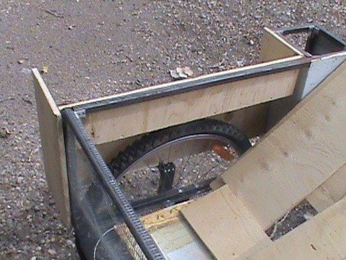
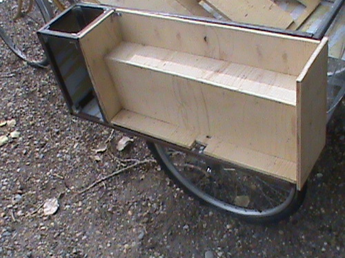
The dry fit has some tweeking to be done but this has to wait till spring.
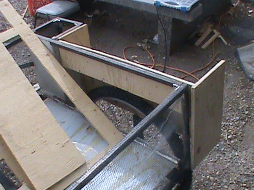
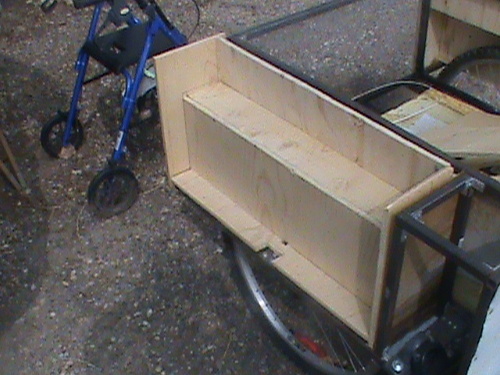
Spring has sprung and grass is griss
We left off with a lot of uncompleted jobs on the trike. We had all winter to think about what needs doing and how to do. I began by removing the front section for straightening. Removed the rear compartments and made the back section ready for the drive axle to be added. I had one rear tire that would not hold air so I replaced the tube and have a happy tire again.The driveline system:
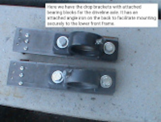
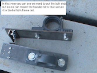

A change of pace was in order. I would have to remove the front section and reinforce it after straightening it. So since I would have the front off anyways, why not install the drop downs for the axle assembly while I'm at it. These drop downs have a piece of 1/2" 'L' channel up at the end that mounts to the lower frame. Two i/4" bolts mount through the lower frame into the 1/2" 'L' channel and 3 x 3/16" bolts mount into the lower facing frame and also the 'L' channel for stability. The pillow bearing blocks mount on the drop downs as shown. Between these pillow blocks go two pillow hubs with their set screws the anchor into the pillow blocks. A steel axle shaft fits into the pillow assemblies and on this axle goes the shown sprockets. These sprockets consist of the sprocket and a hub welded to the sprocket. Placement of the sprockets must line up with the drive gear at the crank and drive gear at the wheel. Set screws on the sprockets lock them in place.
The Drive Axle
My plan for the axle was thwarted by two braces I added to stabilize the trike front. A new plan was needed. The bracing took considerable effort to get it in place and now prevents the drop brackets for the axle pillow blocks to go on. Plan two is to place the pillow blocks horizontal to the rear frame at the inner basket rails. With 1" spacers between the pillow block and the rails there is enough room for the chain drive to work. So we remove 2 drop plates and 2 2" brackets and add 4 x 1" square tube spacers. Our square tubing frame is 3/4" with 1" brackets affixed to joints. The bolts are 3/8". With all this in mind, our pillow block mount holes must be 1-15/16 from the front edge on either side. The other mount holes are 3-5/8 farther than the first set.
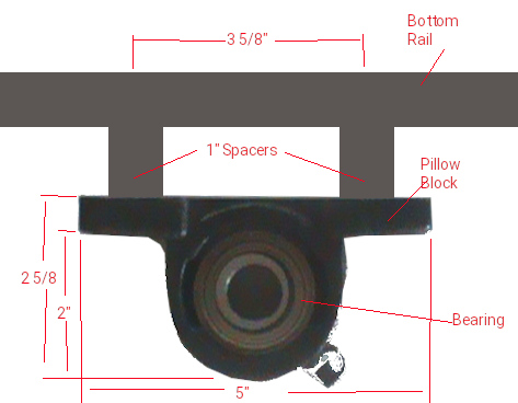
With the new pillow block location solved for it is time to add the bearings to the pillow blocks. One in the picture above is done. While the pillow block has a grease fitting nipple, it is not used as I chose sealed pre greased bearings. On the one side of the pillow block there are two grooves designed for the bearings to fit into the block and using a pry bar you rotate the bearings from horizontal to vertical against the guide grooves. The bearing must be rotated perfectly square with-in the block. The one shown worked great but the second one tried to rotate at an angle and resulted in it being punctured. Needless to say it has to be replaced at a cost of $15.00. The axle is a very tight fit. It needs to pass through one bearing, then a lock collar is fit on and the center sprocket goes next. I should point out that the bearings can go into the pillow blocks with the locks either on the inside or outside. I chose both to be on the inside with the pillow blocks orientated to meet this specification. So we add the second lock collar before feeding the axle through the other pillow block. With a 36" axle and 1.5" pillow blocks centered on the inner basket rails, the axle is flush on the left side. This means that at the other end we have 36" - 30" basket - 1.5" (2 times .75" inside bearing blocks each end) = 4.5" for servicing the outer sprocket.
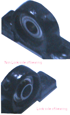
The lock collar is tightened in the direction of rotation. In our case, the main pedal sprocket rotates clockwise which turns the center sprocket clockwise and the shaft clockwise. At the outer end the sprocket likewise turns clockwise to turn the wheel drive gear clockwise (forward motion). When the wheel is free wheeling, no pedal motion is used and so the sprockets do not turn and the shaft / axle is idle. To put the locks in place, move the collars to the bearings, and rotate them in the direction of travel till they seat tight. Using a hex tool tighten down the set screws. We can't line up the center sprocket because the front section of the Trike is not yet re-attached but we can line up the outer sprocket with one of the driveline gears of the wheel cassette. Smaller sprockets turn the wheel faster per revolution of the axle and larger sprockets turn the wheel at a slower rate. When you have chosen the desired sprocket use an Allen wrench to secure the sprocket set screw.

I hope to re-use the driveline chain from the second bike by shortening it and using a chain link. Because we are not going to be switching drive sprockets the trike will act as a standard single speed bike and will have no derailer. A single speed bike chain requires about 1/2" up and down movement at the center point between the sprockets. It might become necessary to use an idler to add tensioning but we will see.
Rear brakes
There are tight constraints in the back wheel wells. Raw space of the wheel wells is 28" L by 5" W by 8" H. From the basket edge to outer frame is 8". The wheel drop outs are set 1/2" in from the inner frame and 3" in from the outer frame. 8" - 3.5" = 4.5" for the wheel. With the compartment in place, there is 5" max for the brake mechanism in width and 8" in height. On the original brake / frame it actually fit over the wheel at an angle.24" rear wheels (12" radius) with 4.5" drop-outs places the bottom edge of the frame 16.5" from the ground and taking into account the frame is .75" thick, leaves 6.75" of wheel inside the wheel well. The rim is 0.5" and the tire is 1.5" to make the 2" of area of concern for braking. The bottom edge of the brake pad must rest 4.75" above the bottom rail if the brake mechanism is mounted vertical (perpendicular to the frame). As you move away from 90 degrees, the brake pad rotates forward and also closer to the frame.

I cut the brake mechanism from the rear assembly of the second bike frame. It has two parts. A solid 'U' shape mounting frame 6.5" H x 4.5" W x 1.5" D and brake levers 4.75" H x 4.5" W x 1" D. The overall assembly will occupy 6.5" H x 4.5" W x 2.5" D. Placing one leg of the 'U' mount frame on the inside rail and the bottom of the 'U' to a bracket off the back of the electronics bay or the battery bay on the other side will accommodate the brakes such that they clear the compartments. Cabling will come out into the basket on the left and through the compartment wall on the right, feeding through the electronics bay to end in the front to back joiner section.
Installing the rear compartments
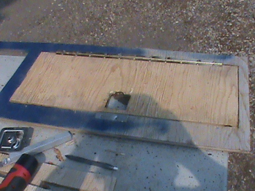
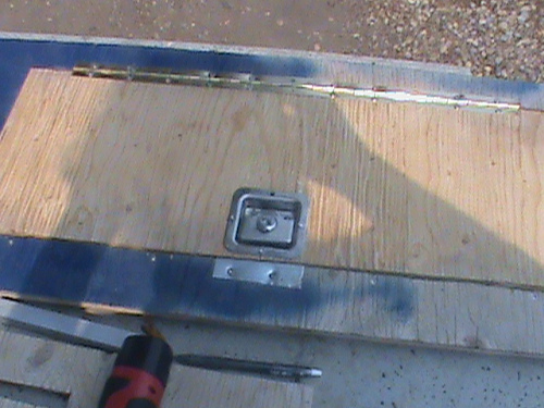
Our side compartments at the rear have a one piece door frame with two doors held on with piano hinges and embedded recessed keyed alike door latches. As luck would have it my paint ran out part way through the painting job. Using my Dremel with a variety of cutting wheels and determination I was able to fit the doors and latches into place. You will note that where the latches are I made metal strikers to facilitate a tight secure fit. In a perfect world, I have preferred to metal clad the the door frames and doors.
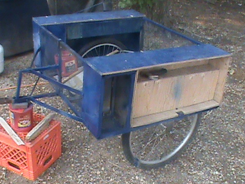
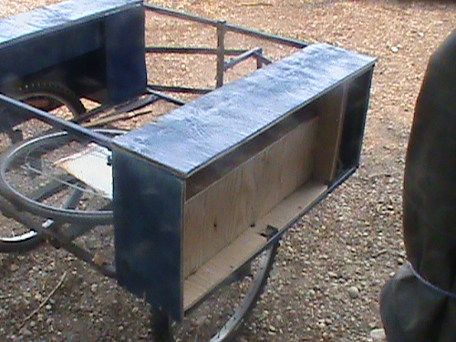
Nothing goes without a hitch! When trying to mount the side compartments, I first tried to use a tap-n-die with no success and had to switch to self tapping screws into the metal frame with better success. It took considerable pressure to get them in and had a tendency to try and pull right through the plywood. If I do it over, I would have pre drilled the pieces with better quality drills bits that don't snap, then tapped the screws into the metal an finished by then hand screwing the pieces into place.
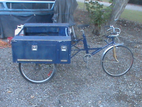
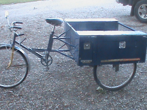
The door frames were then secured to the compartments. I added 4 tie downs to the top of the sides so a tarp cover can be added to cover the basket and eventual solar panels. While I had the top covers and side panels off, I did pre wire for lights and electrical which is shown in the next pictures.
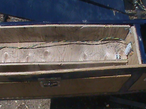
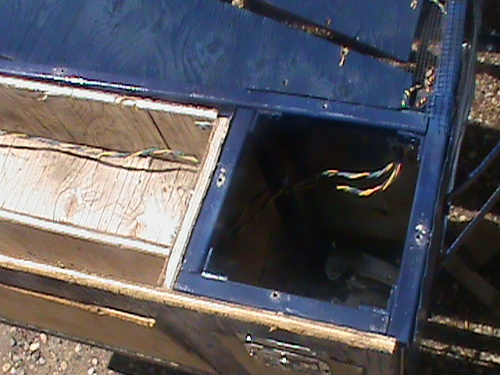
On the right side we have a 5 position barrier strip with GND-Brake-Right signal-Marker (-) - Marker (+), a 2 position barrier for side markers (-/+) and a 12 position barrier to handle lighting to both the front controller and the left side. Wiring passes through the electrical compartment and into a conduit to the front of the basket and into the battery compartment on the left side. This same conduit has 3 x 14:3 wires to the battery compartment and 2 (+/-) wires to the solar panels. A 5 position barrier strip inside the electrical compartment handles Gnd,+6v,+48v to the batteries and Gnd, +57v to the solar panels.
On the left side, the conduit enters the battery compartment and the lighting wires pass into the rear section with again a 2 position marker barrier strip and a 5 position tail light barrier strip. Ideally, I should also pass wires for a trailer but alas I didn't do this.
Restoring the front section

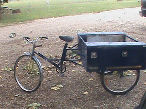
The front seat down pipe was carefully straightened. It had mount holes 7", 9-5/8", 11-5/8" and 12-1/8" from the bottom and taking into consideration for pedal clearance we can only lower the rear frame by 1" which is considerably less than the 2"++ I was hoping for. That rear brace support is once more in the way!
For maximum support against frame twisting, the lower brace must run from the bottom of the rear frame to the front edge of the frames joiner. Then for maximum support of the front frame against bending, it must carry forward to the front fork support. At the top of the fork down pipe we must brace down to the center of the forward running brace and add a solid steel support along the seat down pipe. The picture above left, is of the front reattached, and the right has the bracing put in place.
Two connected problems have to come to light in the design. The seat is higher than the handlebars which is not good. Since the vintage front forks don't support raising the steering bars, I need to lower the seat and or change the bars used on the front forks.
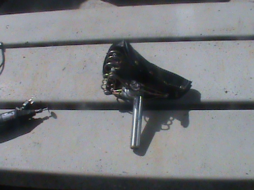
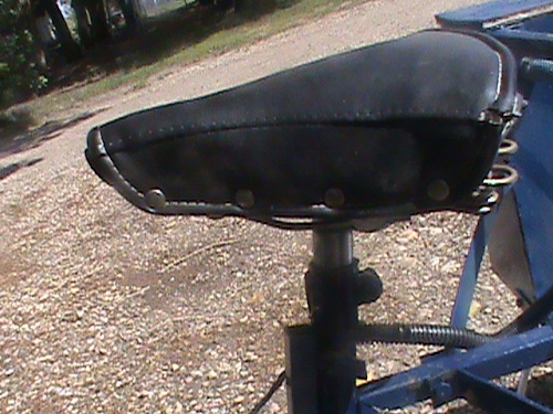
I removed the seat pipe and cut off 1.5" and lowered the seat 2" which improved the relationship considerably. I have ordered a new handlebar which will look something like this when mounted.
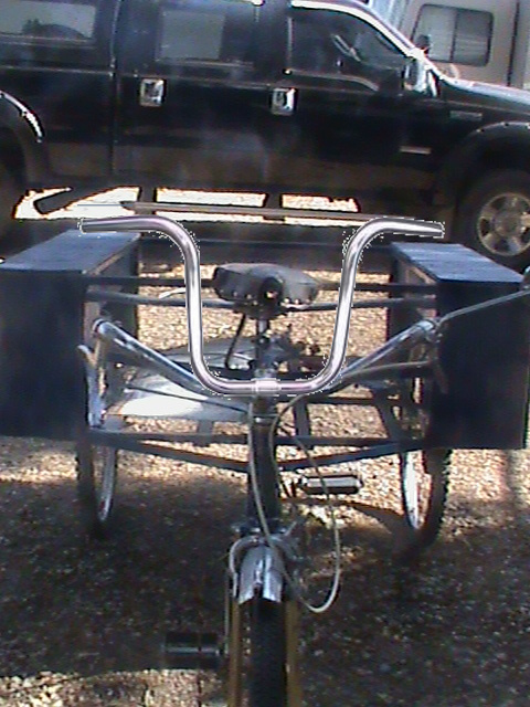

We are now at a crossroad in the project. Design has been of a front hub motor and pedal crank manual based upon a 48v 30ah control system. This is only one approach though. All the physical work so far is the same regardless of the drive method. But, and there is always a but. As is, I can just connect the crank set to the drive axle and have a manual only drive tricycle. The battery pack and or solar would service the brakes and lights. I can continue on with a front wheel hub motor and controller at 48v for a range of 80 to 144 kms with a maximum speed of 50 kph as long as the front forks can handle a hub motor wheel. I can change to a 24v front hub motor with a range of 60 to 100 kms with a maximum speed of 33kph. I can change to a mid drive motor with a change of the axle assembly also with a lower speed and range or as fate would have it use a donated old electric wheelchair drive system that in fact would offer 80 to 144 kms on a modified axle with a speed of up to 110 kph.
The last option may sound ridiculous simply because why would a wheelchair travel so fast. A standard wheelchair is rated for 8mph on 10 inch direct drive tires. The motors (two of them) drive the wheels from a 4800 to 5400 rpm dc motor with a controller that can drive the motors forward or back and convert high rpm to a lower 268 rpm through a worm gear transmition. On our application, we would replace the 10 wheel with a 7 inch sprocket and chain to a 3.5 inch sprocket at the axle and the axle would drive the rear 24" wheel. At maximum speed, 268 rpm becomes 537 rpm at the axle. This results in an effective speed of 38+ mph (63kph). We would need to govern the speed to 50kph by lowering the maximum rpm's.
- Continue with 48v Front wheel hub design
- Continue with 24v Front wheel hub design
- Continue with 24v Mid drive design
- Continue with 24v Wheelchair motor design

The final hurrah! I have an almost ridable trike ready for conversion to a fully electric unit.
Bill of Materials
| Section | Item | Estimate$ | E-Total$ | Actual$ | A-Total$ |
| Basic Trike |
bike 1 bike 2 bike 3 |
$0.00 $100.00 $100.00 |
$200.00 |
$0.00 $9.98 NLR |
$9.98 |
| With the changes along the way I was able to acquire 2 donated bikes and reworked the design such that only 2 bikes were needed. The front 26" wheel is changed to a 26" electric hub wheel. The other bike had 24" fat wheels and became the rear wheels. One of these wheels needed a new tube. The first bikes 26" wheels became the wheels for the trailer. | |||||
| Trike Framing |
0.5" x 48" Sq Steel Tubing (25) 20ga Metal skin () Welding $2/joint . . . 120 cut brackets Compartment Locks (6) Piano Hinge (8ft) |
$160.00 $230.00 $120.00 $36.00 $12.00 |
$558.00 |
$195.00 $0.00 $42.00 $0.00 $9.00 |
$246.00 |
| Building the frame took considerable reworking. Firstly, the .5" square tubing got changed out to .75" square tubing, and instead of getting 25pcs x 48" I only received 23 pcs cut to almost exact lengths. Welding was replaced by 120 cut .5" x 1" 'L' brackets and 480 rivets. A set of donated keyed a-like recessed door locks completed the framework. | |||||
| Driveline |
1" x 48" Steel Rod (1pc) 1" Pillow Bearings (2pcs) 15T Sprocket (3pcs) chngd (2pcs) Chain (15ft) |
$8.55 $25.18 $46.48 $50.00 |
$130.21 |
$38.95 $25.18 $30.98 $0.00 |
$95.21 |
| The steel rod was much more expensive than planned. We are only driving one rear wheel instead of both so sprockets become 2 not 3 and the existing chains are resized to work. | |||||
| Brakes |
Brake F Caliper Brake L Caliper Brake R Caliper |
$26.00 $26.00 $26.00 |
$78.00 $966.00 |
$0.00 $0.00 $0.00 |
$0.00 $351.19 |
| A little reworking and I was able to reuse the brakes from the donated bikes to facilitate the braking of the three wheels. The front brake remained unchanged. The former rear brake of bike one became a transfer caliper on the center mount frame. The transfer caliper then fed the two rear brake cables such that when the rear brake is applied it pulls on the middle caliper which in turn pulls two brake cables to the rear wheels that use the brakes from the second bike Now with electric braking the front brake cable to the center is gone as is the middle 'Y' caliper to be replaced with a pivot and servo. | |||||
| Other |
Pop Rivets Class 5 Bolts (7) Primer (3 cans) Blue Paint (3 cans) Acetate glue Epoxy/ resin 8oz to 16oz |
$3.49 $4.67 3 * $6.95 3 * $6.95 $5.49 $12.78 |
$68.13 |
$3.49 $4.67 3 * $6.95 3 * $6.95 $5.49 $12.78 |
$68.13 |
| $1034.13 | $419.32 | ||||
Adding things up:
For a total of $419.32for a full featured Adult Tricycle. It will be basically maintenance free and can be made fully electric. Not to shabby!
I'd say that is a far cry from using an ICE car for simple trip commuting at a monthly cost of $1000 per month for 5 yrs not including maintenance.
Who'd of thought transportation costs of $60,000 over 5 years could be done for $400. Provide free local travel without need for insurance, fossil fuels, and high maintenance charges which aren't included in this report.

