

48v Front wheel drive Tricycle
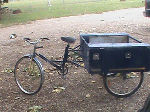
Left is the tricycle before bracing was completed and to the right has bracing in place.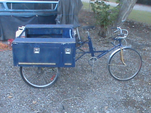
Menu=>:
Each string of LEDs demands 48v @20ma. As such each light string has 48 super bright LEDs. For the marker lights, there are 14 at the front, 2 groups of 6 on each side and two groups of 7 at the back all wired in series.
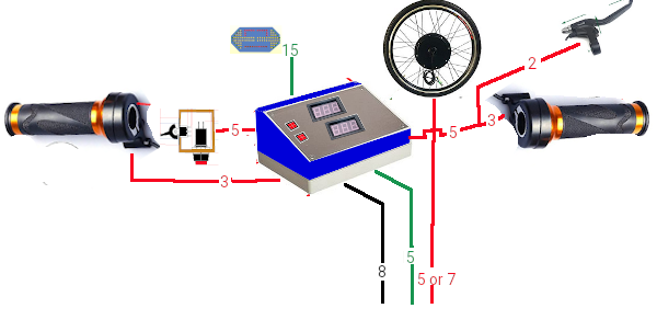
So our front wiring is established. From the left handlebar we have 8 22ga wires to the front controller. From the right handlebar we have 5 22ga wires to the controller. The front lighting will mount later to the front of the control cabinet and it's 15 wires directly connect into the cabinet. 8 18ga wires, 8 22ga wires pass from the control cabinet to the electrical compartment and 5 to 7 wires from the hub motor and speed sensor pass to the ebike controller. That's 23 wires that have to pass from the center of the handlebars to the rear frame.
Electric E-Trike controller
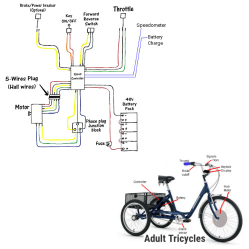
The heart of the Electric Trike is the control unit that fits in the back Electronics bay on the right hand side. On an E-Bike it is both the heart and brain but, and there is always a but, this is a super E-Trike. As a super E-Trike the controller takes direction from a brain called the Main controller. The main controller handles E-Trike drive, Lighting, braking, AC charging, solar charging, and power Inversion. So in this case, the E-Trike controller is powered from Main controller. The Key lock wiring of the controller can be bridged or wired as a secondary key switch. 5 hall effect wires go to the drive motor in the front wheel as does the 3 phrase wires. The throttle takes 3 wires and two sets of 2 wires run to the brake handles as motor cut-out switches. Since I have decided to go with a different motor drive system, The wires coming from the front must connect to the corresponding connections on the ebike controller. The key switch wires and battery connections wire to the main charge controller rather than directly to a key switch and battery.
Battery Packs (applies only to this 48v system)
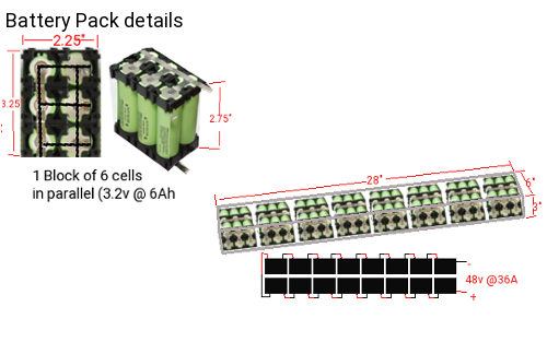
Lets talk space for batteries. Above each wheel at the back there is 28" L x 5" H x 4" W on each side and 8" L x 8" W x 13" H in a dedicated battery compartment. This is enough space for 15 blocks in series of 6 paralleled cells (90 cells @ 36Ah) above each rear wheel and 15 blocks in series of 5 paralleled cells (75 cells @ 30Ah) in the battery compartment. We need 15 cells in series of 4 paralleled cells to make our 48v 24Ah (1152watt) battery system. For economy it would be best to use 3.2v 6000mAh cells (32700 type) rather than the normal 3.2v 1100mAh to 1500mAh (18650). The 32700 cells are 1" diameter x 2.5" instead of 0.72" x 2.15" for the 18650 cells. 1152 watts is higher than the required 960 watts but I am upping it even higher to 1440 watts for range of 120kms. Fully expanded the trike could have a range of 408kms with 102Ah which is phenomenal. At $9 per cell, 24Ah is $576 but at 102Ah cost are bumped to over $2,295. A happy medium is to target 30Ah for $810. This will provide a satisfactory range of 120km.When you place the batteries into a protective enclosure, you will need a positive terminal and a negative terminal and 16 wires going to the cells for monitoring and charging. In low end E-bikes they seldom have BMS charge protection and the charger is seldom carried with the E-Bike. At best, you will find avid E-bike users will carry a second battery pack to swap in as needed. I am not normal so mine will have BMS and onboard charge from AC and / or solar!

Battery bank case
For the batteries, we will have 75 cells arranged as 3 groups of 25 cells with 5 cells in parallel and 5 sets in series per group. Each group will measure 6.75" x 6.75" x 3". So to make the battery pack we need 7" x 7" x 9.375" minimum plastic box size. Material wise we need 22" x 9.375" x .125" bent to form a 'U' shape, 2 ends 7" x 7.5" x .125", and 1 top cover 7.5" x 10.375". Provisions are included for a .5" top cover mounting lip. Acetate glue will mount the ends, and .125" x .5" block separation inside the 'U' form as below.
BMS charge monitoring (applies only to this 48v system)

Our E-Trike will have BMS to protect the Batteries. Depicted below is a Passive BMS charge monitor board that can monitor 15 cell blocks. As a passive system, when a block is fully charged, it's LED lights and charging stops on that group diverting charge to the remaining groups. While all groups are charged initially together, any block that reaches full charge ahead of others stops charging.

I included a four pin battery connection to service needs of the E-Trike and the 16 pin connection for individual battery charge monitoring. Due to the potential charge and drain currents, the four pin connector will need heavier wiring direct to the battery.
The wiring schematic for the BMS boards is shown below. There are 15 identical circuits that each monitor a 3.2v group of cells.

It took some doing but this design is 7" x 5.5" x 1" thick.
Finishing Up: Lights first
At this point we have the completed E-trike with one exception. To be street legal we need full lighting package, and a full working braking system. A Windshield, helmet, and gloves also will be needed.I had planned on adding the lighting system below up on the handlebars till I realized there was no way to implement motor cut-off and brake lights. So, I made a change that involves a new lighting controller mounted between the handlebars and windshield with new circuits and custom lights.
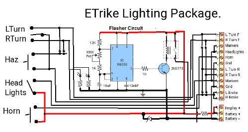
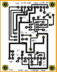
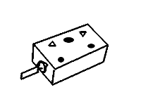
The headlight and Cylon/Signal Lights

Now for our custom lights. The concept here is that I have the lights assembled and tested on their circuit board. A piece of clear 1/16 " Plexiglas is formed into a 5 sided box made to accommodate the PCB. PCB wires are fed through the base and box is filled with clear epoxy resin. Another clear Plexiglas is secured to the open side with acetate glue. The finished assembly can be drilled and mounted as a sealed weatherproof fixture to the sloped top front controller.

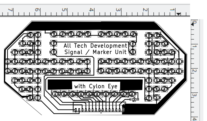
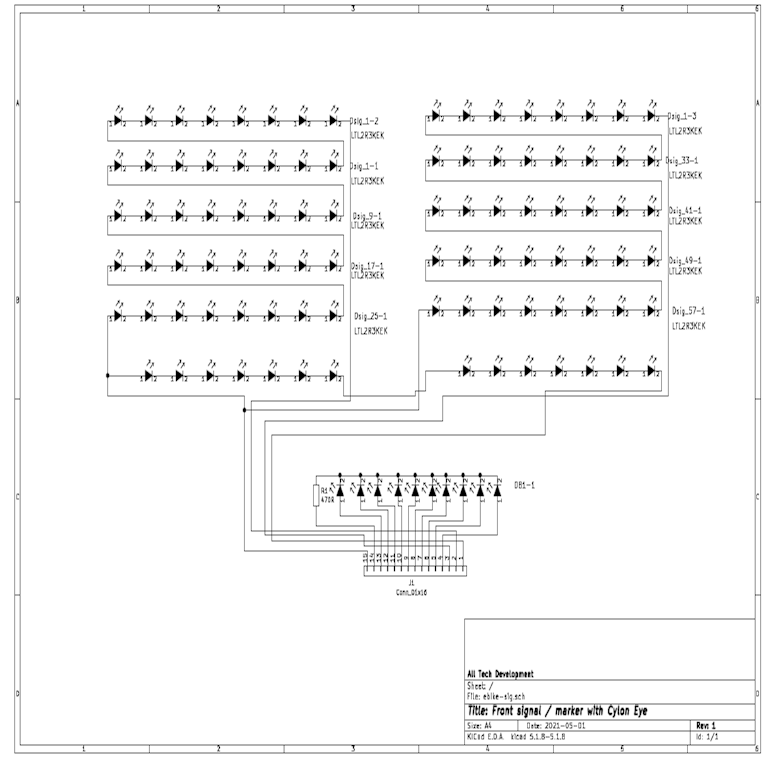
Lighting control Unit
When desiring to mate two boards (in our case the light panel to controller) it is essential to match up things in the design stage before you make the production ones. The mock-up can identify possible problems before committing resources.
Actual size of our front display identifies a height of 4" and width of 7.3" mating with a control board 5.2".
For the markers, we take the front marker line feed it into one marker board, connect the output to a terminal strip, and also feed that strip with a blank wire, Left signal, left brake, and Ground. A sixth wire goes on the terminal strip and then all six pass to the other side. On the other side we take the marker wire and feed it into the marker board and take marker output and all the other wires down to the left tail lights. On the right side we feed Right brake, Right turn, +48v, and the blank wire to the right tail light.

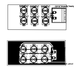

Each of the two taillight assemblies are the same just oriented so the LED arrows face out.

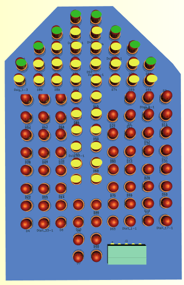
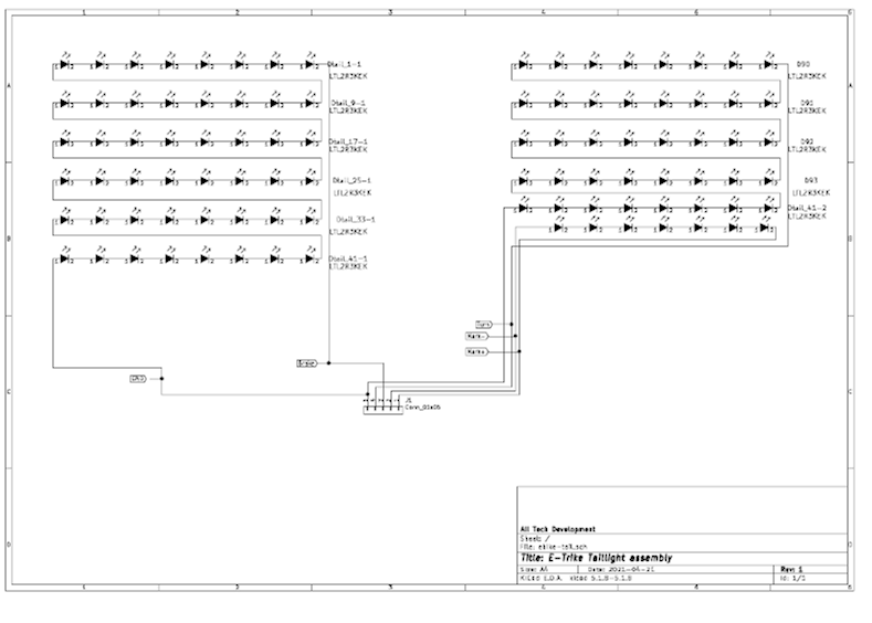
Windshield & Containers round up the finishing.
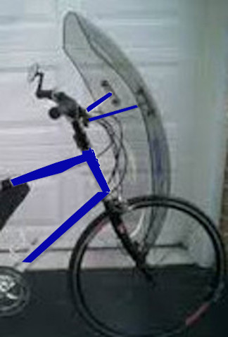
For this Tricycle project there comes a need for custom containers for Batteries, Controllers, and the Windshield itself. Poly carbonate (Lexan) or Acrylic (Plexiglas) are the go to resources that can accomplish this. While we can make the containers using 3D printed forms, the lack of a 3D printer and CAD skills makes it more prudent to go with plastic sheeting which we need for the windshield anyways. Below is my research in such plastic sheets.
Bill of Materials
| Section | Item | Estimate$ | E-Total$ | Actual$ | A-Total$ |
| Basic Trike |
bike 1 bike 2 bike 3 |
$0.00 $100.00 $100.00 |
$200.00 |
$0.00 $9.98 NLR |
$9.98 |
| With the changes along the way I was able to acquire 2 donated bikes and reworked the design such that only 2 bikes were needed. The front 26" wheel is changed to a 26" electric hub wheel. The other bike had 24" fat wheels and became the rear wheels. One of these wheels needed a new tube. The first bikes 26" wheels became the wheels for the trailer. | |||||
| Trike Framing |
0.5" x 48" Sq Steel Tubing (25) 20ga Metal skin () Welding $2/joint . . . 120 cut brackets Compartment Locks (6) Piano Hinge (8ft) |
$160.00 $230.00 $120.00 $36.00 $12.00 |
$558.00 |
$195.00 $0.00 $42.00 $0.00 $9.00 |
$246.00 |
| Building the frame took considerable reworking. Firstly, the .5" square tubing got changed out to .75" square tubing, and instead of getting 25pcs x 48" I only received 23 pcs cut to almost exact lengths. Welding was replaced by 120 cut .5" x 1" 'L' brackets and 480 rivets. | |||||
| Driveline |
1" x 48" Steel Rod (1pc) 1" Pillow Bearings (2pcs) 15T Sprocket (3pcs) chngd (2pcs) Chain (15ft) |
$8.55 $25.18 $46.48 $50.00 |
$130.21 |
$38.95 $25.18 $30.98 $0.00 |
$95.21 |
| The steel rod was much more expensive than planned. We are only driving one rear wheel instead of both so sprockets become 2 not 3 and the existing chains are resized to work. | |||||
| Brakes |
Brake F Caliper Brake L Caliper Brake R Caliper Servo motor |
$26.00 $26.00 $26.00 $25.00 |
$103.00 $1006.00 |
$0.00 $0.00 $0.00 $25.00 |
$25.00 $401.19 |
| A little reworking and I was able to reuse the brakes from the donated bikes to facilitate the braking of the three wheels. The front brake remained unchanged. The former rear brake of bike one became a transfer caliper on the center mount frame. The transfer caliper then fed the two rear brake cables such that when the rear brake is applied it pulls on the middle caliper which in turn pulls two brake cables to the rear wheels that use the brakes from the second bike Now with electric braking the front brake cable to the center is gone as is the middle 'Y' caliper to be replaced with a pivot and servo. | |||||
| Lighting Ctrl |
(1) DPDT-co-sw Paddle switch (1) SPST-mom Horn Sw (2) Push on/off haz/hlight (1) IC 555 timer ic (1) socket 8pin dip (1) PCB Perfbrd (1) Tr1 2N2222A (1) vr1 100k (2) rly1,2 SPDT Relay (2) r1,2 1kr (1) r3 12kr (2) r4,5 470R (1) c1 1uf (1) c2 .01uf (4) diodes 1N4148 (1) Project box (2) Phoenix screw terminal 8p (1) HBAR MNT PWM Brake: (1) IC 555 timer ic (1) socket 8pin dip (1) IC ILQ2 optocoupler (1) socket 16pin dip (1) diodes 1N4001 (2) diodes 1N4148 (1) resister 10KR (2) resister 100KR (1) resister 10R (1) 5v zener (2) 100uf (1) 10uf (1) Phoenix PCB screw terminal 2p (1) 2p header male (1) 16p header male (1) Key switch (1) Rly3 spst CylonEye: (1) 74ls73 jk Flip-Flop (1) 74ls191 4 bit up down counter (1) 74ls154 16 line demultiplex (1) socket 14pin dip (1) socket 16pin dip (1) socket 24pin dip (13) LED's |
$6.99 $3.65 $7.30 $0.75 $0.72 $2.50 $0.57 $0.25 $5.49 $0.40 $0.20 $0.20 $0.69 $0.69 $0.06 $12.00 $3.59 $3.55 0.75 0.72 1.14 0.72 0.10 0.30 0.20 0.40 0.20 1.60 1.12 0.69 1.42 0.20 0.20 15.00 2.43 $1.52 $1.52 $3.95 $0.72 $0.72 $0.72 $2.47 |
$100.79 |
$2.99 $2.29 $4.58 $0.49 $0.15 $ $ $0.15 $5.40 $0.10 $0.05 $0.10 $0.39 $0.39 $0.00 $0.00 $3.59 $0.45 0.75 0.72 0,00 0.72 0.10 0,00 0.20 0.40 0.20 0,00 1.12 0.69 0,00 0.20 0.20 2.43 $1.52 $1.52 $3.95 $0.15 $0.15 $0.15 $2.47 |
$38.76 |
| Lighting control reworked into a windshield mounted unit at handlebars with only turn switch at left handle grip. | |||||
| Lighting |
(1) Headlight (2) Tail lights . . . (208) LEDs . . . PCB stock for 6 displays . . . Epoxy case (2) Turn Light . . . (80) LEDs have 11 of 80 . . . Epoxy case (4) Marker . . . (16) LEDs . . . Epoxy case |
$11.00 $40.00 $30.00 $20.00 |
$101.00 |
$11.00 $39.42 $ $4.00 $15.20 $4.00 $3.04 $2.00 |
$78.86 |
| Purchasing a high luminous LED headlight and creating custom signal and tail-lights made more work but made for a unique and less expensive solution. | |||||
| Accessories |
Helmet Horn Mirror Windshield . . . 24" x 36" Plexiglas . . . 4 Electrical Conduit Clamps - plated (Select size to fit on the forks and/or handlebars) . . . 2 feet 1/4"-20 All-thread Rod - plated (struts) . . . 4 1/4"-20 Acorn Nuts - stainless steel or chrome plated . . . 8 1/4" washers - stainless steel . . . 12 1/4"-20 Nuts - stainless steel . . . 4 Rubber Grommets - 1/8" ID, for 1/8" thick material. . . . 2 feet 1/4" dia. Black Shrink Tubing (to cover the all-thread rod) . . . 1 Inner Tube (to cut into pads to isolate the clamps from your forks and handlebar) . . . 1 yard Felt Cloth - synthetic or wool |
$45.00 $8.00 $9.00 $50.00 |
$112.00 |
$45.00 $0.00 $0.00 $28.00 $ $ |
$73.00 |
| We kept the mirror from the first bike, used a high db horn as part of the lighting control system, and made a custom windshield. | |||||
| E-Trike Convert |
48v 1000W Front Wheel Kit |
$289.00 |
$289.00 |
$ |
$289.00 |
| The E-bike front wheel kit consists of the wheel with embedded hub motor, controller unit, brake handles, key switch and monitor. | |||||
| Battery Pack 48v @30Ah 1440W 120km Range Wght 12 lbs |
(15x5) 3.2v 6A Cells type 32700 (30x3) Cell forms 2m x 8mm Nickel Strip Plexiglas case |
(75) x $9.63 = $722.25 (75) x $1.29 = $96.75 $7.00 $28.00 |
$854.00 |
$ $ $ |
$854.00 |
| The most expensive part of the project is the making of the battery pack(s) | |||||
| Electronics |
(2) Cell Logger . . . Changed to (1) voltage display up front . . . add (1) led voltage level up front (1) 1Charge 208B . . . (15) BD140 transistor $12.45 . . . (15) 20k vr4 pots $1.50 . . . (15) TL431 zr1 $10.65 . . . (30) 20k resistor $1.50 . . . (15) 1k resistor $0.75 . . . (15) LED's $2.85 . . . (15) 330R resistor $0.75 . . . (60) 1N4007 diode $17.40 (1) Solar Ctrl . . . 4k7-5w . . . 240R . . . TIP142 . . . (2) 1N4007 Diode (1) 48v120 Inverter . . . 2w10BD bridge rectifier . . . (6) IFR9540 Mosfet . . . (2) IFR540 Mosfet . . . (3) 1N4007 . . . (1) 1uf Capacitor . . . (2) 2N547 transistors . . . (2) .01uf Capacitor . . . (1) 120-60-625w transformer . . . (1) 12vRelay-10a contacts . . . (4) 470R . . . (2) 1KR . . . (9) 2pos PCB connectors (1) 120v48v Charger . . . 2w10BD bridge rectifier . . . (1) 1uf Capacitor . . . (2) .01uf Capacitor . . . (1) 12vRelay-10a contacts (1) EBike Ctrl |
was $6.04 now $4.60 and $1.20 $181.98 $34.96 $48.65 $24.95 incl |
$296.58 |
$ $ $12.45 $1.50 $10.65 $1.50 $0.75 $2.85 $0.75 $17.40 $2.15 $0.05 $2.74 $0.58 $1.48 $10.08 $3.48 $0.87 $0.10 $1.02 $0.20 $68.85 $6.90 $0.20 $0.10 $13.50 $1.48 $0.10 $0.10 $6.90 Incl |
[$174.77] |
| With our custom electronics we have better control over charging, distribution and monitoring. It also doesn't hurt to be a fraction of the cost. | |||||
|
Solar Array 48v 2Ah 96W |
0.5" U Channel 30Ft (112) Polycrystaline Cells 16ga Wire Tab wire |
$48.00 $48.00 $8.00 $8.00 |
$112.00 |
$44.00 $102.00 $8.00 $32.00 |
$186.00 |
| The solar array also under went some radical change. Instead of 3 panels with two folding over the first panel, I changed from 3 x 1'x 4' panels to 2 x 1.5' x 4' panels that fold up vertically behind the seat. The change means that 220 cells can be worked in to provide 4A of charge instead of 2A. | |||||
| Other |
Pop Rivets Class 5 Bolts (7) Primer (3 cans) Blue Paint (3 cans) Acetate glue Epoxy/ resin 8oz to 16oz |
$3.49 $4.67 3 * $6.95 3 * $6.95 $ $ |
$49.86 |
$3.49 $4.67 3 * $6.95 3 * $6.95 $ $ |
$ |
| $2960.28 | $2179.19 | ||||
Adding things up:
For a rough total of $2960.28for a full featured ETrike with a 144km range at 50km/hour. It will be basically maintenance free for a span of 4 to 5 years then may require $885.00 to go another 4 to 5 years. Not to shabby! 60 months for under $41.00 per month and 120 months (10 years) for under an average of $28 per month.
I'd say that is a far cry from using an ICE car for simple trip commuting at a monthly cost of $1000 per month for 5 yrs not including maintenance.
Who'd of thought transportation costs of $60,000 over 5 years could be done for $3000. Provide free travel without need for insurance, fossil fuels, and high maintenance charges which aren't included in this report.

